Abstract
This paper is devoted to the issue of efficiency of application of fibre optic leak detection systems for identification of small leaks on trunk pipelines. The main methods of leak detection currently in use have been considered, and parametric and fibre optic LDS have been selected for comparative analysis. In the course of the research a model of product leakage from an underground oil pipeline equipped with a fibre-optic LDS was built in the COMSOL Multiphysics software package. The result of the simulation was the estimated time of leak identification by the fibre-optic system, which turned out to be much shorter than that of the parametric LDS. Compensable environmental damage for each type of system was then calculated, confirming the effectiveness of fibre optic LDS for detecting small leaks on trunk pipelines due to the significant reduction in compensable damage.
Highlights
- The simulation and calculation results demonstrated the main advantages of fibre optic LDS over parametric LDS in detecting small leaks (up to 2 % of pipeline capacity).
- Reduction of time spent on detection of a small leak, when using fibre optic LDS, leads to reduction of damage to the environment caused by the leak and subject to compensation.
- The reduction in damage is directly proportional to the pipeline diameter: the larger the diameter, the greater the reduction in damage.
- Therefore, the application of fibre-optic leak detection systems is economically most justified on pipelines with an outside diameter of 1020 and 1220 mm, as the reduction of damage on pipelines of this diameter is the maximum and is comparable to the cost of installation of a fibre-optic LDS.
- Saving of funds spent on compensation of environmental pollution makes it expedient to apply fibre-optic systems also on already operating trunk pipelines, where laying of fibre-optic cable is associated with significant costs.
1. Introduction
Pipeline transport has better technical and economic indicators compared to other types of oil and oil products transport, thus playing an important role in the fuel and energy complex of the Russian Federation. One of the serious problems affecting the efficiency of trunk pipelines is leaks of pumped product. These can occur for a number of reasons, ranging from pipeline deterioration due to long service life or corrosion to unauthorised taps. Leaks cause not only environmental damage, but also material damage due to loss of pumped product, fines in the form of compensation for damage to the natural environment, as well as costs for emergency repair work. Therefore, the importance of an effective leak detection system (LDS) increases.
The issue of leak detection on trunk pipelines is topical. For example, N. E. Zhukovsky, M. V. Lurie, I. A. Charny, M. A. Huseynzadeh, Ph. Carpenter and others. Today there are more than 20 different methods of leakage and tie-in detection on the linear part of trunk pipelines. All these methods are based on different physical laws and phenomena, registration of leakage consequences and have their advantages and disadvantages. Application of one or another method is determined by such factors as pipeline design and characteristics, its operating mode, pipeline route profile and climatic conditions in the areas of laying, properties of the pumped product, cost of the method, etc.
The most widespread on the main pipelines of our country are parametric methods of leak detection and LDSs based on them, as well as combined LDSs, where the method of negative shock waves is used together with parametric methods. They are characterised by simplicity in operation and absence of necessity to install additional equipment, for their operation standard means of telemechanics are enough. Except that in the case of the “pressure wave” method, it may be necessary to install several sensors on the linear part of the pipeline to increase accuracy. However, the disadvantage of this group of methods is relatively low sensitivity of leak detection.
Fibre-optic and acoustic methods and leak detection systems based on them are significantly inferior to parametric methods in economic terms, because to ensure the control of sections of the main pipeline requires significant costs for laying fibre-optic cable or placing a large number of sensors along the pipeline route. However, this group of leak identification methods is superior to parametric and negative shock wave methods in terms of leak location accuracy and sensitivity, especially for low flow leaks. As a fibre-optic LDS, which has found wide application, we can cite the Omega leak detection and activity control system (Omega LDS), used on the main pipelines of PJSC Transneft [1, 2].
2. Relevance
Thus, the main disadvantage of parametric and pressure wave methods is their low sensitivity to small leaks, which do not exceed 2 % of the pipeline capacity. Because of this, detection of such leaks takes a large amount of time, during which the pumped product is released into the environment, causing damage to both it and the pipeline operators. The solution to this problem may be the use of fibre-optic LDSs on trunk pipelines, which allow to promptly detect leaks of up to 0.1 % of the pipeline capacity.
3. Research methods
In order to assess the efficiency of using fibre-optic LDS, including on already operated pipelines, a study was carried out to find the leak detection time by fibre-optic LDS and to compare the obtained values with similar indicators of parametric LDS. The efficiency was determined by shorter leak identification time and reduced environmental damage to be compensated.
As initial data for comparison of leak detection time by parametric LDS we will take from the studies of North American scientists, including a group of employees of Alyeska Pipeline Service Company (operator of the Trans-Alaska Pipeline System) and Emerson [3-5]. Leak identification time values were obtained by offline testing of the leak detection system, based on pre-recorded real-time data of pumping process parameters measured by telemechanics. Based on the test results, probabilistic leak detection functional maps were constructed for parametric LDSs installed on large diameter pipelines (500 mm and larger). One of such maps was used to determine the detection time of small leaks (Table 1).
Table 1Time of detection of small leaks by parametric systems
Leakage rate, % of pipeline capacity | Leak detection time, h |
0.5 | 21 |
1 | 15 |
1.5 | 7 |
2 | 5 |
3 | 3 |
One of the basic principles of operation of fibre-optic LDSs are temperature (monitoring of the ground temperature field near the main pipeline and its changes) and vibroacoustic (recording of acoustic vibrations with subsequent analysis of their source). However, vibroacoustic vibrations can be accompanied by noise of natural and technical origin, which can lead to false alarms of the system. Therefore, when determining the leak detection time, the temperature principle of operation of the fibre-optic LDS was considered.
4. Mathematical modelling
The study of the detection time of low-capacity leaks from trunk pipelines by fibre-optic systems was carried out in the COMSOL Multiphysics software package. The case of oil flow through a defective hole in an underground oil pipeline was considered. The temperature of the transported product, in most cases, exceeds the temperature of the ground, so when oil gets into the environment there is a process of heat transfer from the liquid to the ground, and as a result, the temperature field of the ground changes. Changes in the ground temperature field around the pipeline are recorded by fibre-optic cable sensors and then transmitted via a logic module to the automated workstation (AWS) of the LDS operator in the control room, where, after analysis of the data received, a conclusion on the presence of a leak is made.
Modelling was carried out for oil pipelines with outside diameters of 1220, 1020, 720, 530 mm and pipe wall thicknesses of 12, 10, 8 and 6 mm respectively. The situations with the occurrence of leakage of 0.5; 1 and 2 % of the maximum capacity of the pipeline at eight points located along the perimeter of the pipe cross-section every 45° were investigated. It was assumed that the pipeline was laid in loamy soil. According to the laying technique [6], the fibre optic cable was laid along the pipeline at a distance of 1.5 m from the lateral pipe formation and at a depth of 0.7 m from the ground surface. The following assumptions were made during modelling:
– heat transfer from the pipeline wall to the ground was not taken into account, as this value is significantly less than the heat transfer from oil to the ground;
– when the pumped product flows into the ground, it fills the entire pore space (in real conditions, it may contain residual water or other substances).
Thus, the main processes modelled were the process of oil spreading in the ground after its flow from the pipeline through the leakage hole and the process of heat transfer from oil to the ground. The model was calculated in two stages: stationary (first) and non- stationary, depending on the time elapsed since the leak occurred (second).
5. Results of the study
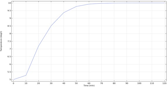
After modelling and calculations, the lines of distribution of pressure and velocities of liquid at the initial moment of leakage occurrence (Fig. 1), graphical representation of oil content in the ground and ground temperature field (Figs. 2, 3) at different times after leakage occurrence were constructed. The main result is graphs of ground temperature changes at the location where the fibre optic cable was laid (Fig. 4). On these, the temperature can be traced, which is recorded by the fibre optic sensors. Leak identification occurs when the system registers a temperature equal to the temperature of the oil pumped through the pipeline. From these graphs, the values of leak detection time were determined.
Fig. 1Pressure and velocity distribution lines of the fluid at the initial moment of leakage occurrence
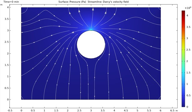
Fig. 2Oil content in the soil 10 minutes after the leakage occurrence
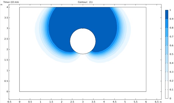
Fig. 3Ground temperature field 10 minutes after the occurrence of an oil leak from the pipeline
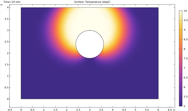
Fig. 4Graph of ground temperature change in the place of fibre optic cable installation
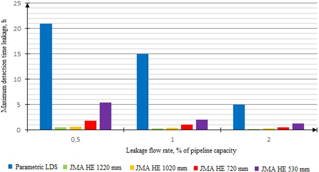
Since the modelling considered the cases of leaks occurring at different points of the pipe cross-section, both the minimum leak identification time (when the leak is located on the side of the pipeline close to the fibre optic cable) and the maximum time (respectively, when the leak is located on the side of the pipeline far from the cable) were obtained (Table 2). After comparing the indicators of the time of small leaks detection by parametric LDS, which are relevant for all investigated pipeline diameters and do not depend on the position of the defective hole in space, with the maximum and minimum values for fibre-optic LDS (Figs. 5, 6), it can be seen that the detection of small leaks by fibre-optic system is much faster. Moreover, the speed of identification of small leaks is the less, the greater their flow rate and the larger the diameter of the pipeline.
Table 2Detection time of small leaks by fibre optic systems
Outer diameter of the pipeline, mm | Leakage flow rate, % of pipeline capacity | Time of leak detection by fibre-optic LDS, min | |
Minimum | Maximum | ||
1220 | 0.5 | 30.5 | 276 |
1 | 19 | 145 | |
2 | 10 | 89 | |
1020 | 0.5 | 38.5 | 295 |
1 | 24 | 143 | |
2 | 14.5 | 87 | |
720 | 0.5 | 108 | 672 |
1 | 64 | 273 | |
2 | 30 | 126.5 | |
530 | 0.5 | 324 | 1012 |
1 | 121.5 | 574 | |
2 | 73.5 | 261 | |
Fig. 5Comparison of maximum detection time of small leaks by parametric and fibre optic systems
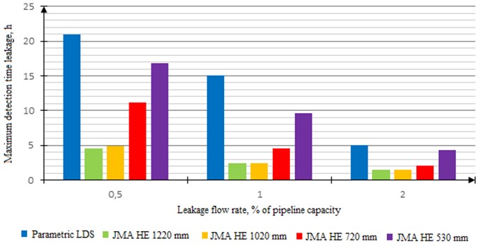
Fig. 6Comparison of minimum detection time of small leaks by parametric and fibre optic systems
6. Practical relevance
Reducing the time taken to detect small leaks by using a fibre optic LDS can significantly reduce the damage to the environment that must be compensated for. In order to assess the effect of reduced leak identification time and reduced damage, a calculation was performed. Environmental damage was calculated for two cases: when using a parametric leak detection system on the main oil pipeline and when using a fibre optic system. As a basis for the calculation was taken the Methodology for determining the damage to the environment in case of accidents on the main oil pipelines (approved by the Ministry of Fuel and Energy of the Russian Federation on 01.11.1995) [7]. The emphasis is placed on the calculation of damage caused by the oil leaving the pipeline in the time interval between the occurrence and detection of the leak. After all, it is this value that directly depends on the time of leak detection by the LDS. The calculation coefficients were taken for the Ural economic region.
Table 3Comparison of environmental damage from small oil spills using two different spill detection systems
Outer diameter of the pipe, mm | Leakage flow rate, m3/h Z (% at Qном) | Environmental damage subject to compensation, RUB | Reduction of environmental damage subject to compensation, RUB | |||
When using parametric LDS | When using a fibre optic LDS | |||||
min | max | min | max | |||
1220 | 50 (0.5) | 58125169 | 1406998 | 12732180 | 56718171 | 45392989 |
100 (1) | 83035956 | 1752981 | 13378015 | 81282975 | 69657941 | |
200 (2) | 55357304 | 1845243 | 16422667 | 53512061 | 38934637 | |
1020 | 35 (0.5) | 40687618 | 1243233 | 9526069 | 39444385 | 31161549 |
70 (1) | 58125169 | 1550005 | 9235444 | 56575164 | 48889725 | |
140 (2) | 38750113 | 1872922 | 11237533 | 36877191 | 27512580 | |
720 | 12.5 (0.5) | 14531292 | 1245539 | 7750023 | 13285753 | 6781269 |
25 (1) | 20758989 | 1476195 | 6296893 | 19282794 | 14462096 | |
50 (2) | 13839326 | 1383933 | 5835582 | 12455393 | 8003744 | |
530 | 5 (0.5) | 5812517 | 1494647 | 4668466 | 4317870 | 1144051 |
10 (1) | 8303596 | 1120985 | 5295849 | 7182611 | 3007747 | |
20 (2) | 5535730 | 1356254 | 4816085 | 4179476 | 719645 | |
Fig. 7Average reduction in environmental damage using a fibre optic leak detection system
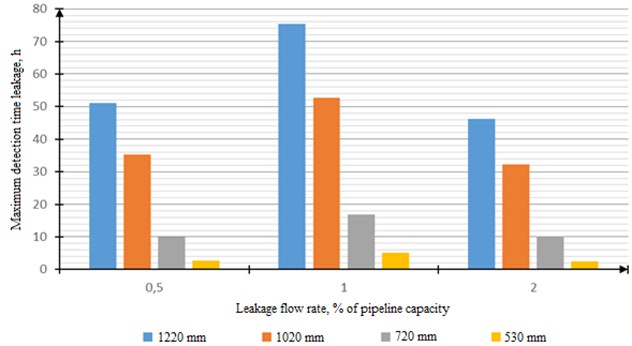
Based on the results of the calculations, the values of environmental damage subject to compensation were determined when using parametric and fibre-optic leak detection systems (Table 3). When analysing the obtained data, it can be said that the use of fibre-optic LDS can significantly reduce the damage caused to the environment (Fig. 7). The greatest effect is observed for trunk oil pipelines with the diameter of 1220 mm: in case of leakage with the flow rate equal to 1 % of the pipeline capacity, the average value of damage reduction reaches 75 million roubles. For oil pipelines with the smallest outer diameter of the pipelines considered in the study (530 mm), the average reduction in environmental damage is 2-5 million roubles, which is the lowest. The reduction in damage depends on the diameter of the pipeline monitored by the leak detection system: the reduction in damage becomes greater as the pipe diameter increases.
7. Discussion
However, a prerequisite for the applicability of temperature-based fibre optic systems is the difference between the temperature of the pumped product and the ground temperature. If these parameters are equal or very close, the use of these LDSs is not effective. In addition, the simulations did not take into account ground movement (e.g. settlement) and thus changes in the location of the fibre optic cable, which can affect the leak detection time. The studies also did not consider the possible false alarms of the leak detection systems considered.
8. Conclusions
The simulation and calculation results demonstrated the main advantages of fibre optic LDS over parametric LDS in detecting small leaks (up to 2 % of pipeline capacity). Reduction of time spent on detection of a small leak, when using fibre optic LDS, leads to reduction of damage to the environment caused by the leak and subject to compensation. The reduction in damage is directly proportional to the pipeline diameter: the larger the diameter, the greater the reduction in damage.
Therefore, the application of fibre-optic leak detection systems is economically most justified on pipelines with an outside diameter of 1020 and 1220 mm, as the reduction of damage on pipelines of this diameter is the maximum and is comparable to the cost of installation of a fibre-optic LDS. Saving of funds spent on compensation of environmental pollution makes it expedient to apply fibre-optic systems also on already operating trunk pipelines, where laying of fibre-optic cable is associated with significant costs.
References
-
N. A. Psyol, “Souica “OMEGA”: safe leak detection using distributed acoustic sensor,” (in Russian), Oil and Gas Transportation and Storage, No. 5, pp. 76–79, 2014.
-
S. I. Vasyutinskaya, V. D. Malkina, and A. I. Turbin, “Optical fibre monitoring system “OMEGA”: neural networks on the guard of pipelines,” (in Russian), Vestnik of Pipeline Technologies, No. 2, 2020.
-
T. Slade, Y. Okamoto, and J. Talor, “Economic benefits of leak detection systems: a quantitative methodology,” Midstream Oil and Gas Solutions, Apr. 2016.
-
P. Carpenter, E. Nicholas, and M. Henrie, “Method gives realistic analysis of leak detection systems,” (in English), Oil and Gas Journal, Vol. 103, No. 11, pp. 53–58, 2005.
-
P. Carpenter, E. Nicholas, and M. Henrie, “Including false positives boosts PLDS performance efficiencies,” (in English), Oil and Gas Journal, Vol. 104, No. 19, pp. 56–59, 2006.
-
“RD-35.240.00-KTN – 076-12 System of integrity monitoring of extended pipeline systems,” (in Russian), PJSC Transneft, 2012.
-
“Methodology for determining the damage to the environment in case of accidents on trunk oil pipelines,” (in Russian), TransPress, Ministry of Fuel and Energy of the Russian Federation, 1996.
About this article

The authors have not disclosed any funding.
The datasets generated during and/or analyzed during the current study are available from the corresponding author on reasonable request.
Shilov Andrey and Nurmukhamedov Chingiz conducted a study use of fibre optic systems for detection of small leaks on trunk pipelines; performed a comparative analysis of parametric and fiber-optic LDS; simulated product leakage from an underground oil pipeline equipped with fiber-optic LDS.
The authors declare that they have no conflict of interest.
