Abstract
The work is devoted to the dynamics of a two-stroke engine. The engine used in sea vessels is considered. A new scheme of the crank mechanism of a two-stroke engine is proposed. An elastic hinge with a given angular characteristic (dependence of the restoring moment on the angle of rotation of the crank) is supposed to be installed between the strut and the crank. The work shows that with certain parameters of the hinge it is possible to obtain a constant angular velocity of the crank for any angle of rotation of the crank. Currently, flywheel inertia can account for up to 80 percent of all moving parts in an engine. Since the mass of engines is large, eliminating the flywheel from the engine design or reducing its mass may be a promising direction in the production of two-stroke engines. The proposed hinge is a structure in which an elastic element (spring or air spring) moves between circular guides of a calculated shape, resulting in a given hinge characteristic. In this work, an air spring was chosen as the elastic element of the hinge, since in this case it becomes possible to change the characteristics of the hinge by changing the pressure in the air spring. The shape of the guides is such that when adding the characteristic of an elastic hinge to the existing characteristic of the engine, an “ideal” characteristic of the considered engine with an elastic hinge is obtained, at which the angular velocity of the crank will be constant. When the angular velocity of the crank changes, a different characteristic of the hinge is required. In progress it is supposed to change the characteristics of the elastic hinge by changing the pressure in the air spring, which is the elastic element of the hinge. It turned out that by changing the initial excess pressure in the air spring it is possible to compensate for the change in the characteristics of the hinge required for the angular velocity of the crank to remain constant at any angle of rotation when its value changes. The results of these studies can be used both in the production of two-stroke engines and for any two-stroke engines.
1. Introduction
Two-stroke engines (DS) are used in various fields of technology. These engines are typically used in applications where a good weight to power ratio is required. For example, DDs are used in hand-held power tools such as lawn mowers and chainsaws [1-4]. DD is used in motorcycles [1-3, 5-8]. Many works are devoted to the study of DD [9-20]. This paper examines the DD used in sea vessels [9]. Data for calculating the crank mechanism (CCM) are also taken from this article. When operating internal combustion engines (ICE), the degree of uneven rotation of the crank is very important. In general, a feature of DD is smoother operation and greater power per unit displacement compared to four-stroke engines.
The crank mechanism of a two-stroke engine is used in the oil and gas industry to drive various pumps and compressors in the following areas:
Oil and gas production:
1) Rod pumps: A crank mechanism converts the rotational motion of the engine into reciprocating motion to drive plungers that pull oil or gas out of the well.
2) Gas compressors: These compressors are used to increase the pressure of natural gas extracted from wells for transportation through pipelines.
Oil and gas processing:
1) Centrifugal pumps: Used for pumping oil or petroleum products through pipes, including refining and transportation processes.
2) Reciprocating compressors: They are used to compress and move gases in processing processes, such as air compression for the operation of pneumatic equipment.
Transportation of oil and gas:
1) Piston pumps: Used for pumping oil or petroleum products through pipelines over long distances.
2) Gas turbine engines: Installed at gas pumping stations to drive centrifugal compressors that move natural gas through pipelines.
Advantages of using the crank mechanism of a two-stroke engine in the oil and gas industry:
1) High power and torque to drive demanding pumps and compressors.
2) Efficient combustion, providing high fuel efficiency.
3) Robust and reliable construction, capable of operating in harsh conditions of the oil and gas industry.
4) Compact size and low weight for easy installation and maintenance.
To smooth out uneven rotation of the crank, flywheels are usually used [21]. Currently, flywheel inertia can account for up to 80 percent of all moving parts in an engine. Since the mass of ship engines is quite large, the problem of eliminating the flywheel from the design of the internal combustion engine or reducing its mass is very relevant.
2. Formulation of the problem
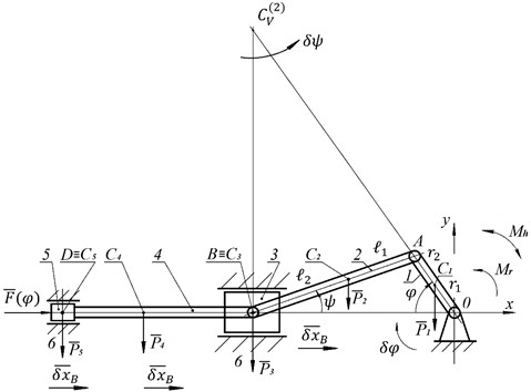
The diagram of the DD under consideration, which has a crosshead in its design, is presented in Fig. 1. The dependences of the force acting on the piston are taken from the article [9]. The given dependencies were interpolated and an analytical formula was obtained (not given here due to its large volume). An elastic hinge with a given characteristic is supposed to be installed between the strut and the crank (point 0).
Fig. 1Two-stroke engine diagram: 1 – crank; 2 – connecting rod; 3 – crosshead; 4 – piston rod; 5 – piston; 6 – stand
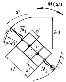
This hinge (Fig. 2) is a structure in which an elastic element, in this case an air spring, moves between circular guides. An air spring was chosen as an elastic element because, unlike a conventional spring, it is possible to change the characteristics of the hinge by changing the pressure in the air spring. The air spring is designed with two symmetrical pistons to obtain symmetrical guides. The shape of the guides is such that the reactions between the air spring rollers and the guides create the necessary torque . By specifying this function analytically, the shape of the guides can be calculated.
Fig. 2Scheme of an elastic hinge with a given characteristic
The system has one degree of freedom. To obtain the characteristics of an elastic hinge, we construct a Lagrange equation of the second kind:
where – the kinetic energy of the engine (Fig. 1); – kinetic energy of the crank; – kinetic energy of the connecting rod; – Kretzkopf kinetic energy; – kinetic energy of the piston rod; – kinetic energy of the piston; – the angle that determines the position of the crank – a generalized coordinate; – generalized speed; – generalized force.
Omitting the calculations, we write the kinetic energy in the following form:
where:
reduced moment of inertia of the motor; – moment of inertia of the crank relative to point 0 (Fig. 1); – moment of inertia of the connecting rod relative to the center of mass; , , , – respectively, the weight of the connecting rod, crosshead, piston rod; piston; – free fall acceleration; , – dimensions that determine the position of the center of mass of the crank; , – dimensions that determine the position of the center of mass of the connecting rod (Fig. 1); .
The generalized force is determined by Eq. (3):
where ; – constant moment of resistance; ; .
To find the value of the constant moment, dependence Eq. (4) was used. The work done by the forces acting on the piston per revolution of the crank is equal to the work done by the moment of resistance per revolution:
Considering that , we obtain the dependence of the moment of resistance on the angle of rotation:
The constant moment of resistance is determined by the following formula:
Let us finally write about the bobbed force in the following form:
The partial derivative in the following form: .
Time derivative: .
We rewrite differential Eq. (1) in the following form:
where:
is time derivative of the reduced moment of inertia Eq. (2); and:
is partial derivative.
Let us set the condition , then, with the dependence determined from condition Eq. (7), the angular velocity of the crank will be constant. This is true for a certain value of the angular velocity of the crank. With a different value of the angular velocity of the crank, a different dependence will be required for the constancy of the angular velocity of the crank at any angle . The formula for determining the dependence (characteristic of the elastic hinge at point 0, Fig. 1, Fig. 2) is as follows:
where is the weight of the crank.
The characteristic dependences of the forces acting on the piston, obtained analytically from data from article [9], are presented in Fig. 3 with a piston diameter 0.3 m.
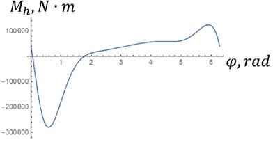
The dependencies obtained by Eq. (7) are presented in Fig. 4. These dependencies are potential, that is, they do not require an influx or outflow of energy per revolution of the crank. If we take the integral , then it is equal to 0 in both versions. Therefore, it is possible to make a hinge according to the diagram in Fig. 2. As can be seen from the figure, the maximum moment in option “a” is approximately 2 times less than in option “b”, since it is proportional to the square of the angular velocity of the crank Eq. (8).
Fig. 3Forces acting on the piston (Fig. 1): 1 – n1= 89 rpm; 2 – n2= 142 rpm
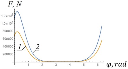
Fig. 4Characteristics of the elastic joint at different crank speeds: m1= 80 kg; m2= 150 kg; m3= 150 kg; m4= 200 kg; m5= 110 kg; I01= 30 kg∙m2; IC22= 50 kg∙m2; r1= 0,2 m; r2= 0,3 m; l1= 0,8 m; l2= 0,75 m; a – n1=89 rpm; b – n2= 142 rpm
a) Characteristics of the elastic joint at different crank speeds for option “a” with low maximum moment
b) Characteristics of the elastic joint at different crank speeds for option “b” with higher maximum moment
3. Determining the shape of the elastic hinge guides
Let’s calculate the guides for the elastic hinge according to the diagram in Fig. 2. We assume that the radii of the rollers in contact with the guides are equal to zero. We do not take into account friction, since rolling friction is minimal, the coefficient of rolling friction hardened steel on hardened steel is 10-6 m. The polar coordinate that determines the shape of the hinge guides can be calculated from the following relation:
where is the force of the air spring ; – displacement of the pneumatic spring piston (Fig. 1); – height of the air spring cylinder; – area of the pneumatic spring piston; 1.25 – polytropic index [22]; – initial excess pressure in the air spring; – characteristic of the elastic hinge, determined by Eq. (7).
Taking the left definite integral Eq. (8) and taking into account connection of the coordinate with the polar coordinate , we get:
Omitting calculations, we write down the dependence , obtained from Eq. (9):
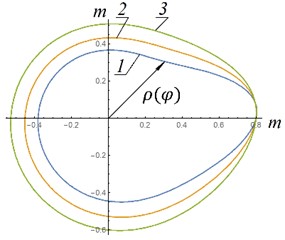
The dependences of the polar coordinate obtained from Eq. (10) are presented in Fig. 5. The definite integral was determined numerically.
As can be seen from Fig. 5, the most acceptable option, which is easier to implement in a real design, is option “a”. In this option, the shape of the guides is as close as possible to a circle. That is, if possible, given design constraints, the height of the air spring cylinder and initial excess pressure in the air spring should be maximum.
Fig. 5Shapes of elastic hinge guides: 1 - p0= 3 MPa; 2 – p0= 5 MPa; 3 – p0= 8 MPa; a, c – n1= 89 rpm; b, d – n2= 142 rmp, a), b) H= 1 m; ρ0= 0,8 m; c), d) H= 0.4 m; ρ0= 0,3 m; A*= 0,031 m2; P1=m1g; P2=m2g; P3=m3g; P4=m4g; P5=m5g; m1= 80 kg; m2= 150 kg; m3= 150 kg; m4= 200 kg; m5= 110 kg; I01= 30 kg∙m2; IC22= 50 kg∙m2; r1= 0,2 m; r2= 0,3 m; l1= 0,8 m; l2= 0,75 m

a) Shape of elastic hinge guides – example No. 1
b) Shape of elastic hinge guides – example No. 2
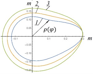
c) Shape of elastic hinge guides – example No. 3
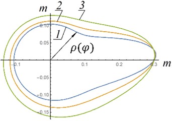
d) Shape of elastic hinge guides – example No. 4
When taking into account the radius of the rollers in contact with the guides, it will be necessary to obtain an equidistant surface to the surface obtained by Eq. (11). Let us consider how the characteristic of the elastic hinge changes with the same guides when the initial excess pressure changes . As an example, let's take the data from which the polar coordinates in Fig. 5, a (dependence 2) were constructed. Let us differentiate Eq. (9):
where is the moment that occurs in the elastic hinge when the initial excess pressure changes (the guides are unchanged).
Considering that , we have , where:
where:
and – constant function determined by Eq. (8) for option a, Fig. 5; 5 MPa – unchangeable initial excess pressure, from which dependence 2 in Fig. 5, option “a” was obtained.
Finally, we have:
where is a constant function (dependence 2 in Fig. 5(a)), determined by Eq. (11).
Analyzing Eq. (14), we can conclude that the right factor is unchanged. Moment will change in direct proportion to the change in the initial excess pressure .
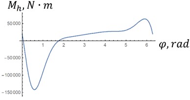
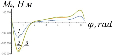
Fig. 6 shows the dependences of the moment in the elastic joint when changing the excess initial pressure and the angular velocity of the crank, obtained from Eq. (8) – dependences 1, 3 and Eq. (14) – dependence (2). Dependences 1 and 3 were obtained with unchanged guides. As can be seen from the figure, dependencies 2 and 3 visually almost coincide. That is, a change in characteristics due to a change in the angular velocity of the crank (from 89 rpm to 142 rpm) can be compensated by a corresponding change in the initial excess pressure: from 5 MPa to 9,5 MPa. The angular velocity of the crank will remain almost constant when the excess initial pressure changes, since the required characteristic (curve 3) practically coincides with characteristic 2, obtained by increasing the initial excess pressure in the air spring. The problems that will need to be solved in the manufacture of the considered elastic hinges include large magnitudes of reactions and , since the moment arms of these reactions cannot in principle be large. This problem is supposed to be solved by selecting materials for the hinge guides.
Fig. 6Characteristics of an elastic hinge: 1 – initial characteristics of the elastic hinge, according to which produced guides 2 in Fig. 5, a; 2 – characteristic of an elastic hinge with the same guides, which are constructed according to dependence 1 of this figure, with increasing initial excess pressure 1.9 times; 3 – characteristics of the elastic joint at rotational speed n2= 142 rpm and with strength F(φ) according to dependence 2 (Fig. 3)
4. Conclusions
The use of an elastic hinge with the required characteristic between the strut and the crank makes it possible to obtain a constant angular velocity of the crank of a two-stroke engine.
When the angular velocity of the crank changes, the characteristic of the elastic hinge for the constancy of the angular velocity of the crank changes significantly.
A pneumatic spring as an elastic element of the hinge, since by changing the initial excess pressure, it is possible to change the characteristics of the hinge.
By changing the initial excess pressure in the air spring of the elastic hinge, it is possible to compensate for the change in the characteristics of the hinge required for the angular velocity of the crank to remain constant when its value changes.
References
-
G. P. Blair, The Basic Design of Two-Stroke Engines. Warrendale, Philadelphia, 1990.
-
I. V. Voznitsky, Modern Low Speed Two-Stroke Engines. (in Russian), Moscow: Morkniga, 2007.
-
V. M. Kondrashov and Y. S. Grigoriev, Two-Stroke Carburetor Internal Combustion Engines. (in Russian), Moscow: Mashinostroyenye, 1990.
-
P. Dempsey, Two-Stroke Engine Repair and Maintenance. New York: McGraw-Hill, 2010.
-
J. B. Heywood, Two-Stroke Cycle Engine. New York: Routledge, 1999.
-
G. Jennings, Two-Stroke Tuner’s Handbook. Tucson: HP Books, 2007.
-
M. Clarke, High Performance Two-Stroke Engines. Vimodrone: Giorgio Nada Editore, 2021.
-
X. Wang and H. Zhao, “A high-efficiency two-stroke engine concept: the boosted uniflow scavenged direct-injection gasoline (BUSDIG) engine with air hybrid operation,” Engineering, Vol. 5, No. 3, pp. 535–547, Jun. 2019, https://doi.org/10.1016/j.eng.2019.03.008
-
E. M. Munyao, Y. Hu, and J. Jiang, “Numerical study of piston group and crosshead guide system dynamics for a two‐stroke marine engine,” Engineering Reports, Vol. 5, No. 2, Aug. 2022, https://doi.org/10.1002/eng2.12564
-
M. Belahcene, R. Mazouzi, and M. Lounis, “Numerical study of thermal effect on the friction of piston-cylinder contact in an internal combustion engine,” Tribology in Industry, Vol. 40, No. 4, pp. 643–653, Dec. 2018, https://doi.org/10.24874/ti.2018.40.04.11
-
V. Arakelian and S. Briot, “Simultaneous inertia force/moment balancing and torque compensation of slider-crank mechanisms,” Mechanics Research Communications, Vol. 37, No. 2, pp. 265–269, Mar. 2010, https://doi.org/10.1016/j.mechrescom.2009.11.007
-
A. G. Provatar, “Increasing the energy efficiency of small-sized ships diesel engines by improving the design of the cylinder-piston group,” Astrakhan State Technical University, 2017.
-
D. Ipci and H. Karabulut, “Dynamic and thermodynamic examination of a two-stroke internal combustion engine,” Journal of Thermal Science and Technology, Vol. 19, pp. 141–154, 2016.
-
Y. G. Mochalov, “Basics of operation, maintenance and repair of marine power equipment,” (in Russian), Kerch State Marine Technological University, Kerch, 2019.
-
A. N. Gorbenko, “Marine internal combustion engines. theory of marine internal combustion engines,” (in Russian), Kerch State Marine Technological University, Kerch, 2022.
-
V. W. Wong et al., “A numerical model of piston secondary motion and piston slap in partially flooded elastohydrodynamic skirt lubrication,” in International Congress and Exposition, Mar. 1994, https://doi.org/10.4271/940696
-
V. H. Arakelian, “Complete shaking force and shaking moment balancing of RSS’R spatial linkages,” Proceedings of the Institution of Mechanical Engineers, Part K: Journal of Multi-body Dynamics, Vol. 221, No. 2, pp. 303–410, Jun. 2007, https://doi.org/10.1243/14644193jmbd26
-
V. Arakelian and S. Briot, “A mechatronic approach to the design of balanced slider-crank mechanisms,” Journal of Mechatronics, Vol. 2, No. 2, pp. 131–135, Jun. 2014, https://doi.org/10.1166/jom.2014.1043
-
D. Zhu, H. S. Cheng, T. Arai, and K. Hamai, “A numerical analysis for piston skirts in mixed lubrication – part I: basic modeling,” Journal of Tribology, Vol. 114, No. 3, pp. 553–562, Jul. 1992, https://doi.org/10.1115/1.2920917
-
N. A. Gutieva, “Study of the dynamics and development of a balancing mechanism for small-sized marine diesel engines,” (in Russian), Astrakhan State Technical University, 2004.
-
E. A. Savastenko, I. A. Nikishin, and S. N. Devyanin, “Irregular ice torque and machines traction quality,” (in Russian), RUDN Journal of Engineering Research, Vol. 2010, No. 3, pp. 100–106, 2010.
-
Y. G. Panovko, Introduction to the Theory of Mechanical Impact. (in Russian), Moscow: Nauka, 1977.
About this article

The authors have not disclosed any funding.
The datasets generated during and/or analyzed during the current study are available from the corresponding author on reasonable request.
Zotov Alexey put forward an idea and conclusions. Tokarev Artem and Valeev Anvar deduced and performed calculations. Fatkullina Gulnaz was responsible for the design.
The authors declare that they have no conflict of interest.
