Abstract
An important task of increasing the energy efficiency of pipeline transport of oil with non-Newtonian properties is to improve the methods of hydraulic calculation of oil pipelines taking into account the complexity of rheological models of such fluids. Obtaining theoretical formulas for friction head losses in turbulent regime is not possible due to the complexity of the turbulent flow structure, so the methodology of hydraulic calculation is based on experimentally obtained dependences. In the article the dependences of friction head loss at turbulent flow of non-Newtonian liquid are analysed on the example of calculation for pipelines of different diameter. As the pumped liquid was considered heavy highly solidified Mangyshlak oil, transported by the main oil pipeline Uzen – Atyrau – Samara. The obtained results show that with the increase of the pipeline diameter the calculation error according to the analysed dependences increases, which is justified by the fact that the indicated dependences are obtained on the basis of experimental studies conducted on pipelines of small diameters.
Highlights
- The paper analysed the dependencies for determining the friction head loss in the hydraulic calculation of oil pipelines transporting high-viscosity, highly solidified oils, using pipelines of different diameters as an example.
- The performed numerical calculations have shown that the largest deviations from the average calculated values of the hydraulic gradient fall on pipelines of large diameter.
- The reason for the deviations is justified by the influence of the experimental conditions, during which the analysed experimental dependences were obtained, in particular, the experiments were conducted mainly on small diameter pipelines.
1. Introduction
One of the most important issues in the design and operation of trunk oil pipelines is the hydraulic calculation of pipelines, in particular, the determination of friction head losses. This issue is of particular importance when pumping viscous and highly solidified (paraffinic) oils.
The complex internal structure of different grades of oil, oil products and liquefied gases causes a great variability of their rheological behaviour. The use of mechanical models of Newtonian and non-Newtonian fluid in rheology allows us to describe the relationship between the kinematic and dynamic state of particles. This relationship is expressed using the rheological properties of the fluid.
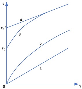
Determination of the rheological properties of the pumped fluid gives an understanding to which model this medium should be attributed at different temperatures: Newtonian, pseudoplastic, nonlinear-viscoplastic, Binghamian (Fig. 1). The Bulkley-Herschel model Eq. (1), used to describe a nonlinearly viscous fluid, generalises all the above types of fluid:
where τ – shear stress, N/m2; τ0 – ultimate shear stress, N/m2; K – measure of consistency, Pa·s; γ – velocity gradient, 1/s; n – flow index.
The temperature dependence of viscosity and ultimate shear stress of highly viscous and paraffinic oils complicates their transportation. For example, when the temperature drops, the pumped product may freeze in the pipeline, which will lead to partial or complete stoppage of pumping and significant costs for its resumption in full.
Fig. 1Dependence of shear stress on shear rate for different fluid models: 1 – Newtonian, 2 – pseudoplastic, 3 – nonlinear-viscoplastic, 4 – Bingham’s model
At high temperatures, highly viscous and paraffinic oils are described by the Newtonian fluid model, but as the temperature decreases, they develop viscoplastic properties of a non-Newtonian fluid. Any pipeline system cannot be in an isothermal state. Despite the use of external thermal insulation and the method of pipeline laying (above-ground, above-ground or underground), heat exchange with the environment takes place, which, in turn, leads to a decrease in the temperature of the pumped medium. Consequently, at some point along the way, the oil will change from a Newtonian fluid to a viscoplastic fluid.
When analysing several works [6, 7, 9] describing pipeline transport of highly viscous and paraffinic oils, the existing formulas and dependencies used for hydraulic calculation of the motion of non-Nentonian fluids through a non-isothermal pipeline were highlighted.
For all flow regimes, the hydraulic calculation of a pipeline carrying viscoplastic fluid is carried out according to the Eq. (2), taking into account the Eq. (3):
where H– friction head losses along the length of the pipeline, m; β* – coefficient in the formula for determining head losses in non-Newtonian oil flow, 1/°C; Q – liquid flow rate in the pipeline, m3/s; d – internal diameter of the pipeline, m; K* – consistency index of the stepped liquid, Pa·s; ρ – density of pumped liquid, kg/m3; L – length of the pipeline, m; Δe – correction for non-isothermicity along the pipeline length; Δr – correction for non-isothermal behaviour along the pipeline radius; b – the degree exponent in the formula for the hydraulic resistance coefficient; a – constant in the formula for the coefficient of hydraulic resistance; g – acceleration of free fall, m/s2.
The values of a, b, n and ρ are determined at the arithmetic mean temperature of the fluid flow at the considered section.
Theoretical derivation of formula for exact calculation of hydraulic head losses at turbulent regime of liquid flow in the pipeline seems to be impossible due to the great complexity of turbulent flow. Therefore, calculations are based on formulas obtained experimentally and they have different error. There are several dependencies for calculating the friction head losses at turbulent flow of non-Newtonian fluid [10].
For example, the Darcy-Weisbach Eq. (4):
where λ – the coefficient of hydraulic resistance; w – average velocity of liquid flow, m/s.
The hydraulic resistance coefficient is determined by the empirical Eq. (5):
where Re* – is the generalised Reynolds parameter.
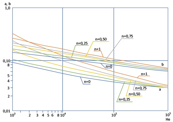
Values of the coefficient a and degree index b, depending on the Hedstrom number (He) and fluid flow index n, are determined graphically (Fig. 2) or by calculation according to dependencies Eq. (6) and Eq. (7) in the intervals of change 0.25 <n≪ 1 and 103<n≪106:
The Hedstrom number is calculated as follows Eq. (8):
At He> 106 the hydraulic resistance coefficient is independent of n, Re*, He and is equal to λ= 0.0156; at He< 103a and b are chosen for values of He< 103 depending on n.
Fig. 2Values of the coefficient a and degree index b in the formula for determining the coefficient ξ depending on the Hedstrom parameter He and the fluid flow index n
For nonlinear-viscoelastic liquids in a turbulent flow regime, the Eqs. (2) and (3) are calculated. At pumping of heated nonlinear-viscoplastic oil at initial sections till the moment of significant wax separation and manifestation of nonlinear-viscoelastic properties the flow of Newtonian liquid is observed. In this case a= 0.3164; b= 0.25 (turbulent mode of flow in the zone of Blasius law), the Eq. (2) taking into account Eq. (3) passes into V. I. Chernikin’s formula for Newtonian fluid Eq. (9):
where ν – kinematic viscosity, m/s2.
To calculate the friction head losses in pipelines carrying nonlinear viscoplastic liquids in the isothermal regime, Eqs. (2), (3) and (9) are used without taking into account the corrections for non-isothermicity Δe and Δr Eqs. (10-12):
Additional formulae can also be used to calculate the coefficient of hydraulic resistance and friction head losses along the length of the pipeline for non-Newtonian fluid flow.
One of these is the formula for calculating the hydraulic resistance coefficient of a non-Newtonian fluid obeying the power law Eqs. (13, 14):
Eq. (13) is valid for turbulent flow of a stepped fluid. For different ranges of values of the degree exponent n, simplified approximations Eqs. (15-17) are proposed:
Lebenzon’s formula, used considering the coefficients for a viscoplastic fluid, can be applied for any values of the Reynolds number Eq. (18):
where μ – the dynamic viscosity of the fluid; β and m – are numerical coefficients depending on the fluid flow regime (Table 1):
where I – the Ilyushin number, which characterises the ratio of the initial shear stress to the viscous friction stress Eq. (22):
where Δr – equivalent roughness of pipeline inner walls, mm.
Table 1Coefficients in the generalised Leibenzon formula for calculations for pumping oil and petroleum products, natural and liquefied gases [7]
Flow regime | λ | A | β, s2/m | m | Scope of application | |
Initial view | Adapted view | |||||
Laminar | 64Re | 64 | 4.15 | 1 | Oil, petroleum product and gas pipelines, liquefied gas pipelines | |
0.0025Re0,233 | 0.0025 | 4.483×10⁻³ | –0.333 | Gas pipelines of the gas distribution system | ||
Transition zone | 1.33×10⁵Re1,02 | 1.33×10⁵ | 1.41×10⁶ | –1.02 | Oil and petroleum product pipelines, liquefied hydrocarbon gas pipelines | |
Turbulent | ||||||
Hydraulically smooth pipes | 0.3164Re0,25f(θ) | 0.3164f(θ) | 0.0246f(θ) | 0.25 | The same, as well as gas pipelines of the gas distribution system | |
0.184Re0,2 | 0.184 | 0.2 | Main gas pipelines | |||
Mixed friction | 0.11(68Re+¯k)0.25f(θ) | 0.206¯(k)0.35Re0.2f(θ) | 0.206¯(k)0.35f(θ) | 0.0166¯(k)0.25f(θ) | 0.1 | Oil and oil product pipelines, liquefied hydrocarbon gas pipelines, gas distribution system pipelines |
0.067(158Re+¯2k)0.25 | 0.1084¯(k)0.1507Re0.0493 | 0.1084¯(k)0.1507 | 8.86×10⁻³¯(k)0.1507 | 0.0493 | Main gas pipelines | |
Quadratic friction | 0.11(¯k)0.25f(θ) | 0.11(¯k)0.25f(θ) | 9.09×10⁻³(¯k)0.25f(θ) | 0 | Oil and petroleum product pipelines, liquefied hydrocarbon gas pipelines | |
0.077(¯k)0.2 | 0.077(¯k)0.2 | 6.37×10⁻³(¯k)0.2 | 0 | Main gas pipelines | ||
* Notes. 1. ¯k – value of relative roughness of the pipeline 2. In laminar mode – except for pipelines pumping liquids with anti-turbulence additives 3. In turbulent mode – when pumping crude oil, petroleum products and liquefied hydrocarbon gases without anti-turbulence additives f(θ)=1 | ||||||
2. Experimental analysis
After identifying the existing dependencies used for hydraulic calculation of the pipeline flow through which non-Newtonian fluid is pumped in the turbulent flow regime, their analysis was performed. It included calculation of friction head losses by Eqs. (4), (10), (11), (16), (18) for pipelines of different diameter and comparison of calculation results, graphically shown in Figs. 3-8.
Heavy oil from Buzachi peninsula (Western Kazakhstan) pumped at the Uzen oil pumping station of the Uzen – Atyrau – Samara trunk oil pipeline was considered as the pumped liquid, in particular, at the complicated Uzen – Atyrau section, through which highly solidified Mangyshlak oils are transported [1-5, 8].
To compare the calculation results, the absolute error for each formula was calculated with respect to the average value of the hydraulic slope isr at a given value of the flow rate (Table 2). For the pipeline D= 350 mm the flow rate = 1000 m3/h was assumed; for D= 530 mm – Q= 1500 m3/h; for D= 720 mm – Q= 2500 m3/h; for D= 820 mm – Q= 5000 m3/h; for D= 1020 mm – Q= 7000 m3/h; for D= 1220 mm – Q= 10000 m3/h.
Fig. 3Calculation of pipeline D= 350 mm with wall thickness 6 mm
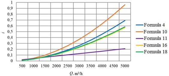
Fig. 4Calculation of pipeline D= 530 mm with wall thickness 8 mm
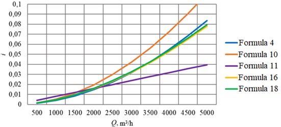
Fig. 5Calculation of pipeline D= 720 mm with wall thickness 9 mm
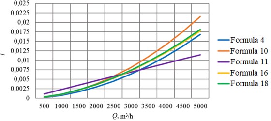
Fig. 6Calculation of pipeline D= 820 mm with wall thickness 10 mm
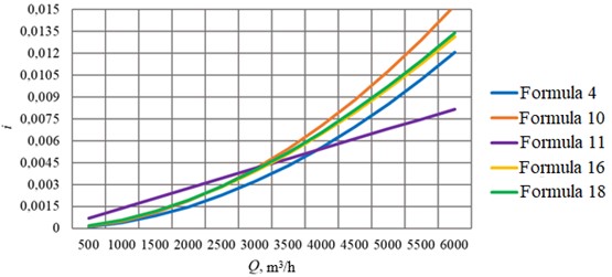
Fig. 7Calculation of pipeline D= 1020 mm with wall thickness 10 mm
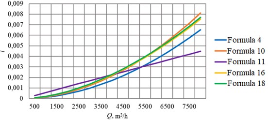
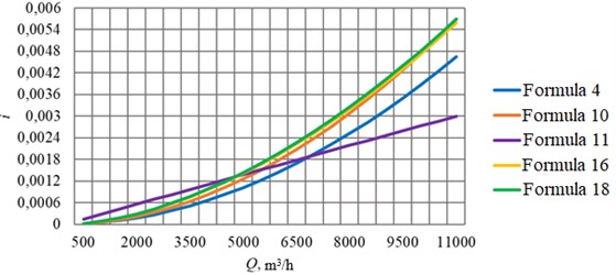
Fig. 8Calculation of pipeline D= 1220 mm with wall thickness 11 mm
The absolute error was determined by Eq. (23):
Average value of hydraulic gradient Eq. (24):
where i – hydraulic gradient.
Table 2Results of calculations of absolute error for each formula with respect to the average value of hydraulic gradient at a given flow rate value
D, mm | Δi4, % | Δi10, % | Δi12, % | Δi13, % | Δi17, % | Δi19, % |
350 | 10.5 | 24.6 | 11.9 | 8.4 | 9.6 | 7.9 |
530 | 15.4 | 12.0 | 18.6 | 4.8 | 6.0 | 4.3 |
720 | 16.0 | 7.8 | 8.0 | 0.3 | 1.0 | 0.9 |
820 | 7.3 | 17.5 | 25.7 | 5.4 | 4.1 | 6.0 |
1020 | 9.2 | 12.8 | 29.4 | 8.8 | 7.4 | 9.4 |
1220 | 9.5 | 10.8 | 36.2 | 11.9 | 10.5 | 12.5 |
To date, there are several dependencies used to determine the friction head losses in the pipeline during pumping of highly viscous and highly solidified (paraffinic) oils, which, depending on the pumping conditions, may have both Newtonian and non-Newtonian properties. Due to the exceptional complexity of turbulent flow in the flow of non-Newtonian fluids, all formulas used to determine the hydraulic resistance coefficient of the pumped medium in practical calculations are obtained experimentally, which makes the calculation results approximate.
The conditions of experiments, during which the dependencies and formulae were derived, were different and, ultimately, affected the result. Analysis of the calculation of the hydraulic gradient of the pipeline when pumping through it in urbulent regime of oil with non-Newtonian properties by different formulae showed differences in the obtained values. This was influenced by different conditions of each of the experiments, during which the dependencies and formulas were derived.
It can also be seen that the largest deviations from the average calculated values of hydraulic gradient occur at larger pipeline diameters. This can be explained by the fact that the experiments to derive the calculation formulae were conducted mainly on smaller diameter pipelines.
3. Conclusions
The paper analysed the dependencies for determining the friction head loss in the hydraulic calculation of oil pipelines transporting high-viscosity, highly solidified oils, using pipelines of different diameters as an example. The performed numerical calculations have shown that the largest deviations from the average calculated values of the hydraulic gradient fall on pipelines of large diameter. The reason for the deviations is justified by the influence of the experimental conditions, during which the analysed experimental dependences were obtained, in particular, the experiments were conducted mainly on small diameter pipelines.
References
-
R. M. Karimov and B. N. Mastobaev, “Changing the technology of oil pumping at the Uzen – Atyrau – Samara oil pipeline with the development of the oil transportation system of Western Kazakhstan,” (in Russian), Transport and Storage of Petroleum Products and Hydrocarbon Raw Materials, No. 2, pp. 9–14, 2010.
-
R. M. Karimov and B. N. Mastobaev, “Rheological features of the West Kazakhstan oil mixture,” (in Russian), Transport and Storage of Petroleum Products and Hydrocarbon Raw Materials, No. 2, pp. 3–7, 2011.
-
R. M. Karimov and B. N. Mastobaev, “Rheological features of commercial oils of Western Kazakhstan,” (in Russian), Bashkir Chemical Journal, Vol. 18, No. 4, pp. 177–181, 2011.
-
R. M. Karimov and B. N. Mastobaev, “Joint transport of high-viscosity and high-setting oils of Western Kazakhstan via the oil pipeline Uzen – Atyrau – Samara,” (in Russian), Transportation and Storage of Petroleum Products and Hydrocarbon Raw Materials, No. 1, pp. 3–6, 2012.
-
R. M. Karimov and B. N. Mastobaev, “Features of pipeline transport of multicomponent systems,” (in Russian), Azerbaijan Oil Industry, No. 1, pp. 60–63, 2012.
-
“Methodology of thermal and hydraulic calculation of main pipelines under stationary and non-stationary modes of pumping Newtonian and non-Newtonian oils in different climatic conditions,” (in Russian), Ministry of Oil Industry VNIISPT oil, Ufa, RD 39-30-139-79, 1979.
-
A. Nikolaev and N. Zaripova, “Substantiation of analytical dependences for hydraulic calculation of high-viscosity oil transportation,” (in Russian), Journal of Mining Institute, Vol. 252, pp. 885–895, Dec. 2021, https://doi.org/10.31897/pmi.2021.6.10
-
M. A. Nugiev, About Non-Equilibrium Rheological Properties of High-Viscosity Oils of Some Fields of Western Kazakhstan. (in Russian), Aktau: JSC KazNIPImunaigas.
-
E. L. Poluboyartsev, S. V. Petrov, E. V. Isupova, and N. A. Chikova, Peculiarities of Transport of Abnormal Oils. Introduction to Rheology. (in Russian), Ukhta: UGTU, 2014.
-
L. S. Abramzon, V. E. Gubin, V. N. Degtyarev, and V. N. Stepanyugin, Pipeline Transport of High-Viscosity and High-Liquidity Oils. (in Russian), 1968.
About this article

The authors have not disclosed any funding.
The datasets generated during and/or analyzed during the current study are available from the corresponding author on reasonable request.
The authors declare that they have no conflict of interest.
