Abstract
This paper presents computational modeling results of a mechanism with hydraulic drive system that performs linear or transversal motion. This mechanism is commonly used in the construction mechanization and the simulation model analysis is obtained by using Matlab/Simulink. Connection of mechanical and hydraulic elements makes this mechanism quite specific and the linking of the mechanical and hydraulic parts is presented. The simulation modeling allows the force and velocity of piston from hydraulic cylinder to be obtained which are necessary components for further projecting of hydraulic drive system.
1. Introduction
Numerous manufacturing and logging machines or transport and handling devices in many industrial sectors use hydraulic systems. For fulfill increasingly standards and requirements, on the other hand achieving quality of production and productivity more accurate mechanisms are created by combining hydraulics, electronics and computer technique [1].
Approaches for simulation and modeling of the systems combined of mechanical, hydraulic and electric parts are many and the most common used software packages among engineers is Matlab which include a subset with tools, Simulink and provides opportunity to build and simulate linear and nonlinear systems. Simulink used model-based design process that allows fast and effective development of dynamic systems, including systems for control, signal processing and communication systems [2]. The model-based engineering is the formalized application of modeling to support system requirements, design, analysis, verification and validation activities beginning in the conceptual design phase and continuing throughout development and later life cycle phases [3]. Like any model-based system design, the usual practice in controller development for an advanced excavator system is to derive the system model first and then develop a controller based on the model. Therefore, deriving a system model is a critical component in the development of an excavator [4].
In [5] is presented modeling method of hydraulic arm which serves as a testing device for basics research in intelligent prosthesis development. The arm model combines mechanical, hydraulic and electric subsystems and uses Matlab as modeling tool with basic task of performing of simple rod movement from one limit position to the other, within rod outer limits. Mathematical simulation of dynamics of a hydraulic system with proportional control valve, linear hydraulic cylinder and mass load is presented in [6]. The mathematical model is created by using Matlab SimHydraulics software allowing to solve the mathematical model based on the physical principle. The subsystems for hydraulic system and for loading were also created in the model for better clarity.
Based on Virtual Prototyping Technology, the co-simulation technology for mining machinery has been studied and applied in [7]. The co-simulation between mechanical system and control system is realized by means of software ADAMS and EASY5. ADAMS provides two kinds of methods for complex mechanical-electronic-hydraulic integration virtual prototype simulation analysis, one as ADAMS/Hydraulic and ADAMS/Control Module to combine the mechanical system simulation tool and control system simulation software.
The structure of this paper is in follows: in Section 2 is presented the model of the mechanism with hydraulic drive system that performs linear or transversal motion. The modeling of the hydraulic parts done by using SimHydraulics [8], and the mechanical parts of the mechanism with SimMechanics [8] are presented in Section 3. After the described process of simulation and the obtained results, follows the last section with conclusion.
2. Mechanism model with hydraulic drive system
The mechanism that will be used for analysis with hydraulic actuator as model has dimensions: 0.16 m, 0.32 m, 0.63 m, 0.35 m as shown in Fig. 1.
Fig. 1Mechanism with hydraulic drive system
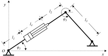
Fluid power actuators can be classified into two groups: linear actuators which are used to move an object or apply a force in a straight line and rotary actuators which are used to move an object in a circular path [9]. The following analysis refers to the presented mechanism with hydraulic drive system that performs linear or transversal motion.
The piston force in extension strokes can be obtained through:
where, is coefficient that takes into account the friction resistance of the pair piston – cylinder and is pressure in the cylinder (opposite rod), is full bore piston diameter. In retraction strokes the piston force is:
where, pressure acting on the rod side and is piston rod diameter.
The choice of cylinder is determined by the force required to move the load and the speed required. Hydraulic cylinders are capable of much larger forces than pneumatic cylinders, however, pneumatic cylinders are capable of greater speeds [9].
The operating pressure in the cylinder is determined as:
where, is safety coefficient. The flow of hydraulic fluid is determined by the following relation:
where, is the displacement of the piston in the hydraulic cylinder and the efficiency coefficient 1 because in the hydraulic cylinders due to good sealing there is almost no leak. The operating pressure and the flow of hydraulic fluid provide important data for further calculation of hydraulic equipment as a part of the hydraulic drive system.
The effective power of the hydro cylinder when it is in extension strokes is determinate as:
where, is the speed of the displacer piston in the hydraulic cylinder.
Since the hydraulic drive has only one hydraulic cylinder it follows that liquid flow through the hydraulic drive in equal to hydraulic fluid . Consequently, the diameters of the pipes in the hydraulic drive can be obtained through:
where, is fluid velocity in the tubes. From here, the determination of the required thickness of the wall of the pressure pipes is obtained as [10]:
where, is stress of pipes material and is maximum fluid pressure in the installation.
3. Simulation of the model and obtained results
The subsystem of the hydraulic system that includes the hydraulic cylinder (hydraulic drive system) is presented in Fig. 2 and for the modeling of hydraulic system the blocks from the library Simscope-SimHydraulics are used.
Fig. 2Hydraulic drive system
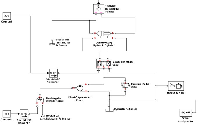
To provide a model for mechanical parts of the mechanism in Figure 3 is presented the created simulation model and for modeling of the mechanical parts, blocks from the library Simscope-sim mechanics are used (Table 1).
The way of connecting the subsystems between hydraulic and mechanical part is presented on Fig. 4.
The model of the mechanism including mechanical and hydraulic parts is shown on Fig. 5.
Table 1Blocks from Simscope-sim mechanics for modeling mechanical parts
Body | Presented parts of the mechanism |
Ground | Fixed bearing |
Revolute | Rotary joint |
Prismatic | Translator joint |
Fig. 3Simulation model of the mechanical parts

Fig. 4Connection between hydraulic and mechanical subsystem
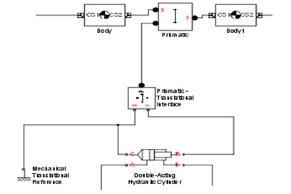
Fig. 5Model of the mechanism including mechanical and hydraulic parts
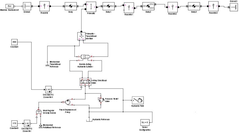
To obtain the displacement, velocity, acceleration and the force of the piston, subsystems are introduced and the completed simulation model of the analyzed mechanism is shown in Fig. 6.
Fig. 6Simulation model of the mechanism
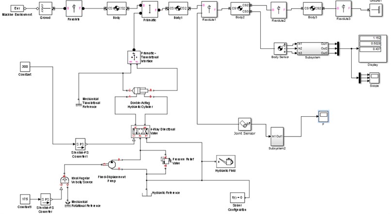
The following computational modeling results of a mechanism with hydraulic drive system are based on the assumption that the pressure in the system is 10 MPa and the value is entered in subsystem which represents the model of the hydraulic drive system.
The changes of values of the piston force from the hydraulic cylinder is presented in Fig. 7 and it is shown that the maximum value that can be achieved in extension strokes is 82 N and in retraction strokes the maximum value can be 66.7 N.
Fig. 7Piston force in a) extension and b) retraction stroke

a)

b)
Fig. 8 presents the diagrams on which is shown displacement, velocity and acceleration of piston from the hydraulic cylinder. The velocity of movement of the piston in extension strokes (Fig. 8(b)) is significant parameter necessary for further projection of the model for simulation and also for selection of hydraulic drive system.
Fig. 8a) Displacement, b) velocity and c) acceleration of the piston

a)

b)

c)
4. Conclusions
Simulation model of mechanism with hydraulic drive system that performs linear or transversal motion is presented in this paper. Through building a simulation model, the process of manual calculation is simplified. The force, displacement, velocity and acceleration of the piston from hydraulic cylinder are obtained from the presented model. This model-based design is a process that allows simplified development of dynamic systems and allows from obtained computational modeling results further optimal design of hydraulic drive system to be achieve.
Connection of mechanical and hydraulic elements makes this mechanism pretty specific. Connection between these two types of elements is made by using block Prismatic Translation Interface. Modeling of hydraulic parts is done using the library SimHydraulics and the mechanical parts of the mechanism with SimMechanics. This allows connection between the cylinder and translation joint to be made and to create model that will contribute to the design and further development of similar dynamic hydraulic drive system.
References
-
Simulation, and Control of Mechatronic Systems. 5th Edition, John Wiley & Sons, 2012.
-
Xue Dingyü, Chen Yang System Simulation Techniques with MATLAB and Simulink. Independently Published, 2019.
-
Barbieri Giacomo, Fantuzzi Cesare, Borsari Roberto A model-based design methodology for the development of mechatronic systems. Mechatronics, Vol. 24, Issue 7, 2014, p. 833-843.
-
Xu Jiaqi, Yoon Hwan-Sik A Review on mechanical and hydraulic system modeling of excavator manipulator system. Journal of Construction Engineering, Vol. 2016, 2016, p. 9409370.
-
Vechet Stanislav, Krejsa Jiri Hydraulic arm modeling via Matlab simhydraulics. Engineering Mechanics, Vol. 16, Issue 2009, 4, p. 287-296.
-
Bureček Adam, Hružík Lumír, Vašina Martin Simulation of dynamics of hydraulic system with proportional control valve. EPJ Web of Conferences, Vol. 114, 2016, p. 02008.
-
Wan Lirong, Wu Xiaowang, Wang Chenglong, Zhang Xin Mechanical-hydraulic integration modeling and simulation of hydraulic support. International Conference on Computer Application and System Modeling, Taiyuan, 2010.
-
The MathWorks Inc.: SimHydraulics User’s Guide. The MathWorks Inc., Natick, MA.
-
Bolton William Correction Elements. Instrumentation and Control Systems (Second Edition), Newnes, 2015, p. 123-150.
-
Barker Geoff Pipe Stress Analysis and Layout of Hot and Cold Piping. Gulf Professional Publishing, 2018, p. 473-499.
