Abstract
Drilling and blasting method is still an important method in the current tunnel excavation construction. Controlling the vibration effect of blasting during construction and its influence on the upper span tunnel is the key problem in tunnel construction. Based on Chongqing Science City tunnel excavation blasting project, combined with the tunnel blasting vibration monitoring and testing, this paper analyzes the propagation attenuation law of tunnel blasting vibration along the rock mass, and studies the load characteristics of the explosion stress wave propagating to the existing high-speed railway tunnel. Considering the influence of the buried depth of the blasting source, a mathematical prediction model of the attenuation law of the upper span existing high-speed railway tunnel caused by tunnel blasting is established. Based on the dynamic finite element numerical calculation method, the influence of blasting vibration on the structure of the existing high-speed railway tunnel under construction is analyzed, and the propagation and attenuation law of blasting vibration along the tunnel contour is studied. Based on the ultimate tensile stress criterion, the ultimate shear stress criterion and the Mohr criterion, and compared with the results obtained from the numerical simulation, the blasting safety criterion model of the existing high-speed railway tunnel over the tunnel is established.
Highlights
- Impact load of blasting falling body on the safety of HDPE pipe was analyzed.
- The process of pipeline collapse is analyzed by numerical simulation.
- The mathematical prediction model of tunnel blasting is established.
1. Introduction
With the continuous expansion of China's high-speed railway network, tunnel construction is a key component, and its construction technology and safety management are facing higher and higher requirements. Especially when blasting construction is carried out above or near the existing high-speed railway tunnel, how to ensure the safety of the existing tunnel structure and reduce the impact on the operation of high-speed railway has become an important issue to be solved urgently. Leng Zhendong improved the safety of blasting construction by adjusting blasting parameters and adopting anti-vibration measures in the aspect of blasting vibration control in the construction of the existing tunnel on the upper span. In terms of structural damage assessment, Jiang Nan et al. analyzed the damage of the structure after blasting construction by conducting damage assessment, which provided an important basis for blasting construction [1-2]. At the same time, Zhang Zhen used non-destructive detection technology and numerical simulation method to carry out quantitative assessment of structural damage. In the aspect of safety criterion research, Xie Quanmin et al. conducted a systematic study on the blasting safety criterion of the existing high-speed railway tunnel over the tunnel. Through the analysis of engineering examples and theoretical research, they summarized some feasible safety criteria and construction norms, which provided guidance for practical projects [3-5].
In foreign countries, the research on the blasting safety criterion of existing high-speed railway tunnels across the tunnel has also received certain attention. In terms of blasting vibration control technology, S. P. Singh et al. have improved the safety and effect of blasting construction by improving blasting technology and introducing new materials [6-9]. Mahendra Gadge et al. have adopted advanced monitoring system and vibration control technology to effectively control blasting vibration. In terms of structural damage assessment technology, Hamdia et al. adopted advanced structural damage assessment technology, including laser scanning, acoustic emission monitoring, etc., to accurately assess the structural damage after blasting construction [10-15].
Different geological conditions (such as rock type, joint development, groundwater, etc.) have significant effects on blasting wave propagation and energy attenuation, so it is necessary to evaluate the specific effects of these geological factors on the existing tunnel structure more accurately. At the same time, a single blasting may not cause immediate significant damage to the tunnel structure, but long-term and multiple blasting operations may produce cumulative effects, resulting in a gradual decline in structural performance. Therefore, it is necessary to study the effect of long-term cumulative blasting vibration on the durability of tunnel structure [16-19].
Although some progress has been made in the research of cross-tunnel blasting safety standards for existing high-speed railway tunnels, there are still some deficiencies and areas to be innovated. Although a lot of theoretical research has been carried out, some of the research results are not satisfactory in practical engineering. This may be because the bridge between theoretical research and engineering practice has not been fully established, which makes it difficult to directly translate theoretical results into effective construction techniques and specifications. The optimization of blasting construction parameters is a complicated process, which needs to consider many factors such as geological conditions, tunnel structure and construction environment. However, there are still deficiencies in the optimization of construction parameters, which makes it difficult to achieve the best blasting effect. Although the existing structural damage assessment technology can reflect the impact of blasting construction on structures to a certain extent, its accuracy and comprehensiveness still need to be improved. For example, nondestructive testing techniques and numerical simulation methods may be interfered by many factors in practical applications, leading to bias in evaluation results.
Therefore, this paper aims to comprehensively study the current research situation at home and abroad, and conduct an in-depth study on the blasting safety criterion of the existing high-speed railway tunnel across the tunnel, focusing on the tunnel blasting excavation engineering, relying on the Science City tunnel project (Section 1), and combining with the on-site blasting vibration monitoring in the tunnel, analyze the propagation attenuation rule of the tunnel blasting vibration along the rock mass. Study the load characteristics of the explosion stress wave propagating to the existing high-speed rail tunnel, and adopt the principle of dimensionless analysis to establish a mathematical prediction model of the attenuation law of the upper span existing high-speed rail tunnel caused by tunnel blasting (Section 2); Based on the dynamic finite element numerical calculation method, the propagation and attenuation law of blasting vibration in the main line tunnel are analyzed (Section 3). At the same time, combined with the theory of explosion stress wave and the strength failure criterion, the safety criterion model of the lining structure of the existing high-speed railway tunnel is established (Section 4).
2. General situation of blasting engineering of Science City Tunnel
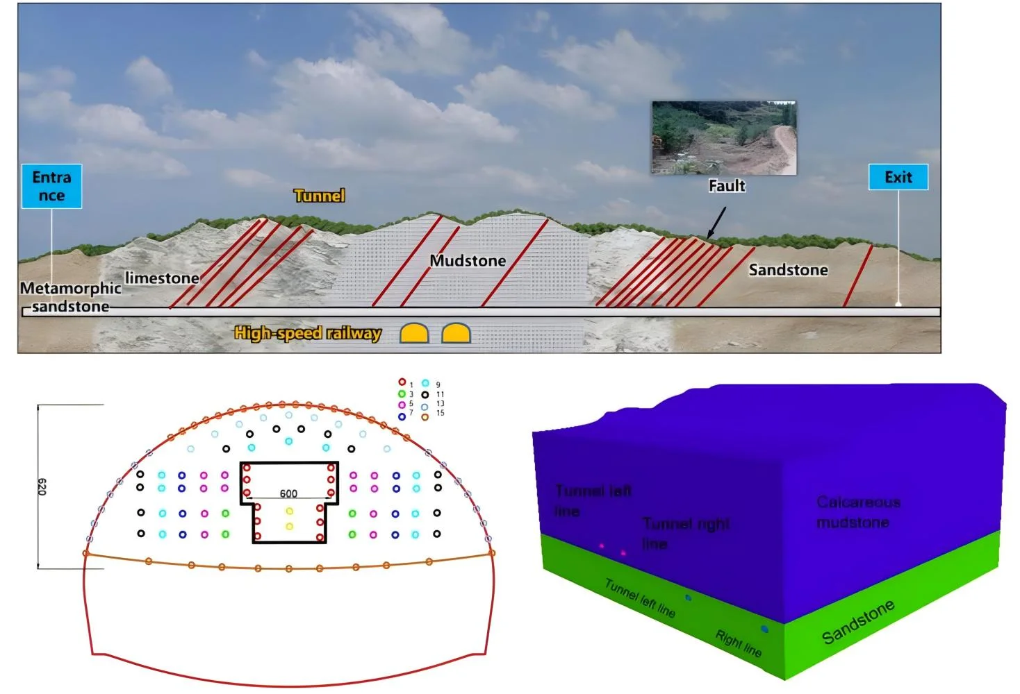
The tunnel project of Science City starts from Xishan Interchange in the west and ends at Hongchoufang Interchange with a total length of 6.8 km and 4.1 km. The tunnel construction limit has a net height of 5.0 m and a net width of 13.5 m. The maximum longitudinal slope of the tunnel is 3 %, as shown in Fig. 1.
The total length of the Science City tunnel is 4.1 km, the net surface size is 5.0 m×13.5 m, and the maximum longitudinal Angle of the tunnel is 3 %. The distribution diagram of the tunnel geological cross section is shown in Fig. 1.
During the tunnel construction, this area needs to cross the existing Chengdu-Chongqing high-speed railway tunnel, which greatly increases the complexity and risk of construction. In order to ensure the smooth progress of tunnel construction, the safety of the high-speed railway tunnel crossing above must be strictly protected. In view of the key role of blasting operation in such projects, its construction difficulty and potential risks cannot be ignored. The main challenge was the complex and varied geological conditions the tunnel traversed, consisting mainly of calcareous mudstone, limestone and sandstone formations that required very high blasting techniques. To this end, the project adopts the drilling and blasting excavation method, which requires precise control of blasting parameters to minimize the vibration impact on the surrounding environment and ensure the structural safety and operational stability of the existing Chengdu-Chongqing high-speed railway tunnel. To sum up, the entire construction process requires not only superb technical level, but also strict safety management measures and meticulous monitoring system. In this paper, the Ⅳ level surrounding rock is the main research object, and the blasting excavation by the upper and lower step method is adopted. The schematic diagram of blasting parameters is shown in Fig. 2. The cut hole affects the smooth blasting effect and the circular penetration of tunnel excavation, so the good or bad blasting effect of the cut hole is particularly important for obtaining good blasting effect. In the follow-up research process, the impact caused by the cut hole blasting is mainly targeted, because the cut blasting is often the largest single stage charge. The blasting vibration caused by it is also greater.
Fig. 1Geological cross section distribution diagram of tunnel
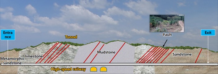
Fig. 2Schematic diagram of blasting parameters (Unit: cm)
a) Full section gun hole layout

b) Schematic diagram of wedge cut perforation Angle
3. Field vibration test in tunnel
3.1. On-site monitoring data analysis
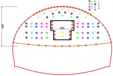
The existing high-speed railway tunnel and Science City tunnel are monitored and analyzed by using the measuring and control blasting vibration monitoring instrument of Chengdu China Science Center, and the on-site blasting vibration monitoring data are counted. The specific monitoring point layout diagram is shown in Fig. 3.
Data regression analysis is carried out on the two tunnels according to Sadowski formula, where: is the earthquake safe velocity, cm/s; is the coefficient related to geological conditions; is the maximum burst charge of a single stage, kg; is the distance from the detonation source, m; is the attenuation coefficient of blasting. The regression formula of vibration velocity of Science City tunnel is:
The vibration velocity regression formula of the existing high-speed railway tunnel is as follows:
Fig. 3Schematic diagram of vibration measurement point layout of Science City tunnel
According to the relevant provisions of the Blasting Safety Regulations [16,20-21] on the frequency, as shown in Table 1, combined with the analysis of the field monitoring data of the Science City tunnel and the existing high-speed railway tunnel, it can be seen that the blasting vibration frequency is mostly greater than 50 Hz, so the control threshold of the peak vibration speed is selected as 15 cm/s. Through the analysis of Table 2, it is not difficult to find that, the peak value of the maximum vibration tunnel in the tunnel is less than 2.32 cm/s, which is far less than the tunnel peak control threshold, indicating that the blasting construction scheme design of Science City tunnel is reasonable, safe and reliable, and the surrounding rock of the tunnel is stable.
Table 1Safety permissible standard of blasting vibration
Category of protected objects | Safety allows particle vibration speed , cm/s | ||
10 Hz | 10 Hz 50 Hz | 50 Hz | |
Traffic tunnel | 10-12 | 12-15 | 15-20 |
3.2. Establishment of mathematical model of attenuation law of existing high-speed railway tunnel
According to the relevant field measurement experiments and numerical simulation research results of a large number of scholars on the attenuation law of blasting vibration in rock and soil mass, it can be seen that the propagation of blasting vibration in rock and soil mass is related to a variety of factors (Hastings M. C. 2005, Govoni J. J. 2008), and the main relevant parameters are shown in Table 3.
From Buckingham’s theorem of dimensional analysis ( theorem), shock wave overpressure () can be expressed as:
From Buckingham’s theorem of dimensional analysis ( theorem), Rock and soil mass point vibration peak velocity () can be expressed as:
Table 2Statistical table of vibration parameters of Science City tunnel and existing high-speed railway tunnel
Science city tunnel | There is a high-speed rail tunnel | ||||||
Distance (m) | Dosage (kg) | Vibration speed (cm/s) | Main frequency (Hz) | Distance (m) | Dosage (kg) | Vibration speed (cm/s) | Main frequency (Hz) |
16 | 38.6 | 2.32 | 105.25 | 22 | 33.6 | 2.1 | 100.2 |
15 | 30 | 1.92 | 132.3 | 22 | 27 | 2.01 | 88.9 |
16 | 36.4 | 1.85 | 109.5 | 22 | 27 | 1.31 | 98.6 |
20 | 33.6 | 1.12 | 105.5 | 22 | 30.8 | 1.32 | 98.5 |
20 | 28.6 | 1.01 | 112.2 | 22 | 30.8 | 1.41 | 85.6 |
20 | 27 | 1.23 | 113.5 | 22 | 28.6 | 1.13 | 88.6 |
20 | 27 | 1.26 | 123.2 | 22 | 28.6 | 2.23 | 87.8 |
25 | 34 | 1.01 | 122.0 | 40 | 30 | 1.35 | 68.5 |
25 | 28.4 | 1.05 | 103.5 | 45 | 29.4 | 1.2 | 69.6 |
25 | 24 | 1.25 | 89.3 | 50 | 30 | 1.65 | 70.5 |
40 | 27.4 | 1.58 | 89.5 | 55 | 29.8 | 1.15 | 62.3 |
45 | 30.2 | 1.25 | 65.5 | 55 | 29.4 | 1.68 | 60.1 |
50 | 27.4 | 1.11 | 66.3 | 65 | 29.8 | 1.21 | 58.6 |
55 | 30.2 | 1.07 | 58.5 | 73 | 27.6 | 1.15 | 50.1 |
65 | 28.6 | 0.71 | 66.8 | 75 | 36 | 1.35 | 48 |
70 | 30.6 | 0.63 | 70.5 | 81 | 27.6 | 1.11 | 49.6 |
80 | 36.4 | 0.61 | 50.5 | 85 | 32 | 1.32 | 50 |
73 | 27.6 | 0.52 | 45.6 | 90 | 36.6 | 1.68 | 52.5 |
81 | 27.6 | 0.49 | 48.5 | 95 | 39 | 0.54 | 51 |
90 | 36.6 | 0.387 | 38.3 | 100 | 29.2 | 0.12 | 51.3 |
100 | 36.6 | 0.42 | 38.2 | 100 | 36.6 | 0.13 | 50.6 |
Table 3Important physical quantities involved in tunnel blasting shock wave
Categories | Variables | Dimension |
Dependent variables | Rock mass point vibration displacement | L |
Rock and soil mass point vibration peak velocity | LT−1 | |
Rock and soil mass point vibration acceleration | LT−2 | |
Rock and soil mass point vibration frequency | T−1 | |
Argument | Charge in a single section of tunnel blasting | M |
Distance between the particle and the source | L | |
Elevation difference between the particle and the existing high-speed rail tunnel | L | |
Distance between burst sources (i.e. tunnel depth) | L | |
Rock and soil mass density | ML−3 | |
Velocity of seismic wave propagation in rock and soil mass | LT−1 | |
Time of detonation | T | |
Note: The density of rock and soil mass and the propagation speed of sound wave are assumed to be constant; The dimension of L - length; T - the dimension of time; M - the dimension of mass | ||
Substituting Eq. (4) into Eq. (3) yields:
By recombining , , , we get the dimensionless number :
where: , , and are respectively the index of , , .
For a certain site, and can be approximated as constants. Therefore, a functional relationship can be considered from Eq. (6):
To sum up, this functional relationship can be written as:
Then:
where: and are the coefficients given in the process of function transformation respectively.
Then :
Eq. (10) is the prediction formula of blasting vibration velocity without the influence of elevation difference. By substituting Eq. (10) into Eq. (9), we can get:
Then Eq. (11) can become:
Then a mathematical model reflecting the attenuation law of blasting vibration velocity under flat terrain conditions under the influence of elevation difference is established as follows:
where: represents the site influence coefficient; is the attenuation coefficient of peak strength of vibration velocity; is the effect coefficient of the peak intensity of vibration speed elevation, is the effect coefficient of the horizontal distance of vibration speed.
By comparison with Eq. (10) and Eq. (13), it can be seen that during the propagation attenuation of the existing high-speed railway tunnel in the rock mass, the elevation between the measuring point and the explosion source is affected. In order to evaluate the rationality and accuracy of the prediction model of blasting vibration of the existing high-speed railway tunnel established by Eq. (13), it is compared with the traditional prediction formula according to the fitting coefficient of the fitting curve, as shown in Table 4.
Table 4Prediction model of blasting vibration peak value of existing high-speed railway tunnel
Eq. (11) | Correlation coefficient | Eq. (14) | Correlation coefficient |
0.47 | 0.84 |
4. Numerical simulation calculation method and reliability verification
4.1. Blasting loading method
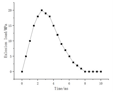
Combined with the theory of explosive stress wave [1-2], the blasting load is loaded in the form of triangular load, and the initial pressure of the explosive is:
Type: is the explosive detonation pressure; is the explosive density; is the detonation speed of the explosive; is the isentropic index of the explosive. The approximate value is 2-3 [3], in this paper, and are the diameter of the cartridge and the diameter of the hole.
In this paper, emulsified explosive of, is adopted, and the specific loading form is shown in Fig. 4.
Fig. 4Loading curve of equivalent explosion impact load
4.2. Numerical model and parameter selection
4.2.1. Model size and boundary conditions
Through Flac3D numerical simulation, the dynamic response of new tunnel construction to existing high-speed railway tunnels can be predicted and evaluated, which provides a scientific basis for the optimization of construction scheme and the reinforcement of tunnel structure. According to the research needs, a 3D numerical model with dimensions of 120 m×80 m×99.65 m was established. The distance between the bottom of the model and the tunnel is set to 3 times that of the tunnel to reduce the influence of boundary effects on the simulation results. Two main formation materials, calc mudstone and sandstone, are considered in the model.
The physical and mechanical parameters of these two materials are shown in Table 5, including density, elastic modulus, Poisson's ratio, internal friction Angle, cohesion force, etc. These parameters are the basis of simulation calculation. Non-reflective boundary (such as static boundary or viscous boundary) is used on the tunnel contour to reduce the influence of wave reflection on the simulation results. The remaining boundaries are free boundaries. The stress distribution and change of the rock mass around the existing tunnel are analyzed, and the influence on the stability of the tunnel structure is evaluated. Monitor the displacement and deformation of existing tunnels during construction, especially the deformation of tunnel linings, to assess their impact on the safety of high-speed rail operations. The propagation law of vibration wave caused by new tunnel construction in rock mass and the response characteristics of existing tunnel to vibration wave, including vibration frequency and amplitude, are studied. In the laboratory, it is usually necessary to use a series of precise test methods and equipment to measure physical and mechanical parameters such as rock density, elastic modulus, Poisson’s ratio and shear modulus. The relevant physical and mechanical parameters are shown in Table 5.
Fig. 5Tunnel numerical model
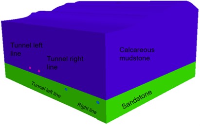
Table 5Selection table of relevant physical and mechanical parameters
Parameters | Units | Type | |
Calcareous mudstone | Sandstone | ||
Density | g/cm3 | 2.2 | 2.6 |
Modulus of elasticity | GPa | 0.1 | 0.45 |
Shear modulus | Mpa | 39.06 | 187.5 |
Poisson's ratio | - | 0.28 | 0.2 |
Cohesion | Mpa | 10 | 15 |
Friction Angle | ° | 22 | 45 |
Compressive strength | Mpa | 130 | 150 |
Yield strength | Mpa | 0.4 | 0.8 |
4.2.2. Reliability analysis of numerical simulation
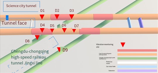
In order to verify the rationality of the numerical simulation results, monitoring points consistent with the site were set up according to the actual situation of tunnel blasting excavation. The site monitoring points are arranged as shown in Fig. 6. In order to verify with the field blasting vibration test data, the numerical simulation and measured particle vibration velocity peaks of each monitoring point are listed in Table 6.
Through the analysis of Table 6, it is not difficult to find that there is little difference between the field monitoring data and the simulated data, and the maximum error is 13.35 %. The main reason for the above phenomenon is that the numerical simulation fails to fully take into account the effect of the joint surface and the attenuation of the particle vibration velocity peak and frequency attenuation in the rock and soil medium. However, despite this limitation, it is still feasible to apply the relevant parameters obtained by the numerical simulation research to the study of the dynamic response of existing tunnels during the construction of new tunnels after proper correction and verification. This requires us to pay more attention to the simulation of the complexity of geological structures in the subsequent research to improve the accuracy of prediction.
Table 6Velocity peaks of numerical simulation and field monitoring
Monitoring Points | Numerical simulation (cm/s) | Resultant velocity(cm/s) | Field measurement (cm/s) | Resultant velocity(cm/s) | Percentage error (%) of closing velocity | ||||
D1# | 1.312 | 1.354 | 1.372 | 2.33 | 1.1 | 1.225 | 1.171 | 2.02 | 13.35 |
D2# | 1.132 | 1.231 | 1.812 | 2.46 | 1.123 | 1.534 | 1.742 | 2.57 | 4.57 |
D3# | 1.523 | 1.985 | 1.985 | 3.19 | 1.42 | 1.975 | 1.924 | 3.10 | 2.89 |
D4# | 1.255 | 1.672 | 1.187 | 2.40 | 1.264 | 1.615 | 1.167 | 2.35 | 1.84 |
D5# | 1.412 | 1.567 | 1.685 | 2.69 | 1.6 | 1.646 | 1.523 | 2.75 | 2.03 |
5. Existing blasting vibration effect of high-speed railway tunnel
5.1. Particle vibration change rule when a new tunnel is straddling an existing high-speed railway tunnel
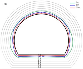
Seismic waves generated by blasting propagate from far to near, and gradually transform from body waves to surface waves. In order to understand the vibration change law of tunnel particles caused by blasting seismic waves at different tunnel sections, when the new tunnel is directly across the existing high-speed railway tunnel, the particle distribution law of the existing high-speed railway tunnel contour at the distance of 1 m, 5 m and 30 m from Zhangziplane is selected.
It is not difficult to see from Fig. 6 that in the near area of tunnel blasting, the peak vibration velocity of particles in the tunnel is greater in the vertical direction than in the radial direction of the tunnel than in the axial direction of the tunnel (), indicating that the vibration in the vertical direction is the main direction of vibration propagation in the area closer to the face of the hand, which is due to the larger buried depth of the tunnel and the better grade of the surrounding rock of the tunnel. With the initiation of the V-shaped cut area, the seismic waves generated by tunnel blasting mainly include body waves and surface waves. Since there are free planes in both axial and radial directions of the tunnel, they all attenuate to a certain extent, resulting in a large peak vibration velocity in the vertical direction of the tunnel. At the same time, as the distance from the tunnel palm surface continues to extend, the vibration propagation speed of particles inside the tunnel gradually shows a slowing trend. Specifically, the attenuation in the direction is the most significant, followed by the direction, and the attenuation in the direction is relatively minimal. This phenomenon shows that the attenuation of particle velocity in the tunnel is mainly concentrated in the direction, that is, as the distance away from the tunnel face increases, the vibration energy dissipation in the direction is the most obvious.
From Fig. 6 (a), the propagation law of particles in the tunnel in the direction, it is not difficult to see that the vibration speed of surrounding rock is small at the spinner of the tunnel, while the vibration speed is larger at the vault, arch foot and floor of the tunnel. This is because the tunnel has an elliptical structure and stress concentration is prone to occur at the arch foot of the tunnel, resulting in excessive stress here. Due to the larger stress at the arch foot of the tunnel, the wave impedance here is larger, so the peak vibration velocity here is larger. At the same time, due to the high ground stress of the floor, blasting excavation leads to the redistribution of the overall stress in the tunnel, and the unloading rebound occurs, resulting in the propagation of stress waves here being amplified to a certain extent.
Fig. 6Peak vibration velocity distribution of tunnel excavation section
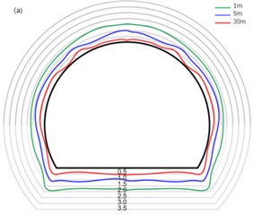
a) direction
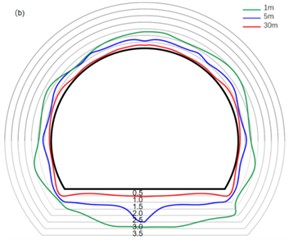
b) direction
c) direction
From Fig. 6(b), the propagation law of the tunnel particle in the vertical direction, it is not difficult to see that the vibration speed of the tunnel floor and the tunnel side wall is large, and the arch foot is the smallest. Tunnel excavation leads to the free surface in the tunnel, which provides conditions for the further deformation of the tunnel. At the same time, the vertical vibration in the tunnel corresponds to the shear wave in the tunnel blasting seismic wave, that is, SH wave and SV wave. The shear wave is very easy to reflect and refract in the free plane and the rock mass interface, so the vertical vibration speed is larger at the tunnel top, side wall and bottom plate near the tunnel blasting area, and the arch foot and spinner due to the phenomenon of stress concentration and special site structure, resulting in the vibration speed caused by stress waves is small.
5.2. Calculation model of safety threshold of high-speed railway tunnel
Combined with the numerical simulation results, the stress and vibration velocity values at different positions of the existing high-speed railway tunnel were calculated, and the stress and vibration velocity of the lining of the high-speed railway tunnel were analyzed by regression according to the principle of least square method, as shown in Eq. (6). As the existing high-speed rail tunnel is made of C30 concrete, after the actual engineering situation, for safety considerations, the value of the existing high-speed rail tunnel is calculated according to C25, and its ultimate tensile strength is 1.46 MPa. Combining with Eq. (16), the threshold value of blasting vibration safety control of the existing high-speed rail tunnel can be obtained as 19.41 cm/s:
Stress waves are pressure fluctuations caused by the energy released instantaneously by blasting, which are characterized by high pressure, high speed propagation and high energy. When the blasting operation is carried out in the mountain directly above the tunnel, the shock wave generated by the explosion will propagate through the mountain, and part of the energy will be converted into stress wave and transferred to the tunnel structure. Such impact load can cause the structure to produce dynamic strain and stress, and affect the stability and strength of the structure. The dynamic stress may exceed the static bearing capacity of the structure, resulting in the destruction of the structure.
The impact and vibration effects in the process of stress wave propagation can make the tunnel structure vibrate. In the long run, vibration will cause fatigue damage to the structure and weaken the strength and stability of the structure.
The propagation speed of P wave and S wave is expressed by:
where: is the propagation speed of p-wave; is the propagation speed of shear wave; is the dynamic elastic modulus; is Poisson’s ratio; is density.
According to Snell’s rule, when light passes through the interface of two media, the relationship between the incidence Angle and the refraction Angle satisfies the following:
where the is the incidence Angle and is the refraction angle.
On the free surface of concrete lining, when the incident wave is P-wave, the stress-strain generated by P-wave and S-wave contains the following relations:
where: is the reflection coefficient of the stress wave. , , , are the incident and reflected P-waves and S-waves.
Suppose there is a plane burst wave in the rock mass that travels with velocity , and a displacement wave that travels with velocity . According to stress wave theory, dynamic stress can be expressed as:
where: and are the vibration speed of the concrete particles of the tunnel lining caused by the longitudinal wave and the transverse wave. [], [] are the ultimate tensile stress strength and shear stress strength of tunnel lining concrete.
By combining Eqs. (17-23), the safety criterion model of blasting vibration of the existing high-speed railway tunnel under blasting stress can be obtained, as shown in Eq. (13):
where: , is the safe vibration speed determined by the limit tensile stress strength criterion under the action of S wave.
Under the action of blasting vibration, the ultimate tensile strength of tunnel concrete lining may be improved to some extent. This is because the blasting vibration will produce severe dynamic load and vibration effect, and produce strong force on the concrete structure. This force can promote the friction between the particles inside the concrete to reduce, make the concrete more compact, improve its mechanical properties. Specifically, under the action of blasting vibration, the particles in the concrete will have relative displacement, and the friction between the particles will be reduced, thus reducing the internal friction resistance. In this way, under the action of external load, the concrete is more prone to displacement and deformation, making the internal stress distribution more uniform. Since the tensile strength of concrete is related to its internal stress distribution, the ultimate tensile strength of concrete may be improved when the stress distribution is more uniform.
The relationship between static tensile limit strength and dynamic tensile limit strength of lining material is shown in Eq. (24):
where: is the dynamic tensile strength; is static tensile strength; is the loading rate, ; is any loading speed (1); is the loading speed, 0.1 MPa/s; is the dynamic strength improvement coefficient. Generally, 1.32 is taken.
5.3. Safety threshold
The dynamic tensile strength of C25 concrete is obtained by synthesizing the dynamic strength improvement coefficient obtained from Eq. (26). According to the characteristics of concrete materials, the dynamic elastic modulus is generally 1.2 times of the static elastic modulus, and the dynamic elastic modulus of C25 concrete is calculated. The parameters used in C25 concrete material are shown in Table 7.
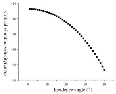
The experimental data clearly reveal the influence of different types of seismic waves (P-wave and S-wave) on the critical vibration velocity of tunnel lining structure at different incident angles. Specifically, when the longitudinal wave (P wave) acts on the tunnel lining at an incident Angle ranging from 0° to 40°, the critical vibration velocity required for structural damage increases correspondingly with the gradual increase of the incident Angle. This phenomenon indicates that the resistance of the lining structure to vibration is enhanced when the longitudinal wave is inclined. It is particularly significant that the minimum critical vibration velocity that the tunnel lining structure can withstand under the extreme case of vertical incidence of the P-wave (i.e. the incidence Angle is 0°) is determined to be 14.73 cm/s, which is an important threshold to ensure the safety of the structure under this condition.
Table 7Parameters of C25 concrete material
Compressive strength / MPa | Static tensile strength / MPa | Dynamic tensile strength / MPa | |
25 | 1.1 | 1.46 | |
Density / (g·cm-3) | Static elastic modulus / GPa | Dynamic elastic modulus / GPa | Poisson's ratio |
2.5 | 26.2 | 31.4 | 0.2 |
On the other hand, the behavior of S-wave in the range of 0° to 40° is completely opposite, and the critical vibration velocity of blasting induced by S-wave decreases gradually with the increase of incident Angle. This means that the tunnel lining structure is more vulnerable to damage when the shear wave is oblique incident. Especially, under the condition of vertical incidence of shear wave, the minimum critical vibration velocity of the lining structure to resist damage is reduced to 32 cm/s, which is much lower than the value of vertical incidence of longitudinal wave, which highlights the potential threat of shear wave to the safety of tunnel structure.
Further analysis shows that the failure mechanism caused by different waveforms is also different: under the action of P-wave, the tunnel lining structure first occurs tensile failure, which is caused by the direct compression and tension of the P-wave medium, resulting in the internal stress of the material exceeding its tensile strength. Under the action of shear waves (S-waves), the structure is the first to experience shear failure, because the shear waves mainly cause the transverse vibration of the medium, resulting in the shear stress concentration and exceeding the shear strength of the material.
Fig. 7 intuitively shows the complex relationship between critical vibration velocity and incidence Angle under these two waveforms, providing important theoretical basis and reference data for predicting and controlling the impact of blasting vibration on tunnel lining structure in engineering practice. With a deeper understanding of these relationships, engineers can more accurately design blasting plans and take effective shock absorption measures to ensure structural safety and stability during tunnel construction and operation.
Fig. 7Relation between critical vibration velocity and incidence angle
The safety threshold of concrete blasting vibration velocity obtained by numerical simulation is 19.41 cm/s, which is larger than the result obtained by theoretical analysis. This is because although the two methods are based on the ultimate tensile stress criterion, the numerical simulation cannot completely simulate the actual engineering situation, resulting in errors in the results. Therefore, it is not recommended to adopt only a single method of numerical simulation when designing and studying similar projects. Finally, for the sake of safety, the blasting vibration safety threshold of the existing high-speed railway tunnel can be set as 14.73 cm/s, and the calculated results can be used as the safety criterion of the blasting vibration speed of the project, so as to guide the blasting operation on site efficiently and ensure the safety and stability of the tunnel. The theoretical analysis of safety criterion of blasting vibration velocity of tunnel lining based on ultimate strength criterion is reliable.
6. Conclusions
In the near area of tunnel blasting, the peak vibration velocity of particles in the tunnel is greater in the vertical direction than in the radial direction than in the axial direction (). At the same time, the vibration propagation velocity of particles in the tunnel gradually decreases with the increase of the distance from the tunnel palm face, and with the increase of the distance from the tunnel palm face, the attenuation of particle velocity in the tunnel is mainly in the direction.
At the spinner of the tunnel, the vibration velocity of surrounding rock is small, while at the vault, arch foot and floor of the tunnel, the vibration velocity is large. At the same time, due to the high ground stress of the floor, blasting excavation leads to the redistribution of the overall stress of the tunnel, and the unloading rebound occurs, resulting in the propagation of stress waves here being amplified to a certain extent.
According to the theoretical analysis of the safety criterion of blasting vibration velocity of tunnel lining based on the ultimate strength criterion, the safety threshold of blasting vibration velocity of concrete is 19.41 cm/s, which is greater than the result of theoretical analysis. For safety consideration, the safety threshold of blasting vibration of existing high-speed railway tunnels can be set as 14.73 cm/s. Using the safety criterion of blasting vibration velocity of the project, it can guide the blasting operation on site efficiently and ensure the safety and stability of the tunnel.
References
-
Z. Leng, Q. Gao, and W. Lu, “Rock drilling blasting energy regulation theory and application technology research progress,” (in Chinese), Journal of Metal Mine, No. 5, pp. 64–76, 2023, https://doi.org/10.19614 / j.carol carroll nki jsks. 202305006
-
Y. Peng, G. Liu, L. Wu, Q. Zuo, Y. Liu, and C. Zhang, “Comparative study on tunnel blast-induced vibration for the underground cavern group,” Environmental Earth Sciences, Vol. 80, No. 2, Jan. 2021, https://doi.org/10.1007/s12665-020-09362-z
-
M. Liu, L. Jin, F. Chen, R. Zhang, and X. Du, “3D meso-scale modelling of the bonding failure between corroded ribbed steel bar and concrete,” Engineering Structures, Vol. 256, p. 113939, Apr. 2022, https://doi.org/10.1016/j.engstruct.2022.113939
-
W. Zhao, T. Zhang, Y. Wang, J. Qiao, and Z. Wang, “Corrosion failure mechanism of associated gas transmission pipeline,” Materials, Vol. 11, No. 10, p. 1935, Oct. 2018, https://doi.org/10.3390/ma11101935
-
F. Li, K. Wu, S. Li, C. Wang, Y. Liu, and Z. Dou, “Study on the dynamic response characteristics of lining structures in large-section tunnel blasting using JH-2 model analysis,” Scientific Reports, Vol. 14, No. 1, May 2024, https://doi.org/10.1038/s41598-024-60918-6
-
F. Q. Zhu, H. Q. Liu, and J. Zhang, “The finite element simulation analysis of urban subway shield tunnel,” Applied Mechanics and Materials, Vol. 711, pp. 514–519, Dec. 2014, https://doi.org/10.4028/www.scientific.net/amm.711.514
-
Q. Xie, Y. Jia, and K. Ding, “Chaos characteristics of tunnel blasting vibration signal analysis,” Journal of vibration and shock, Vol. 9, No. 3, pp. 238–244, 2022.
-
P. Pal Roy, “Emerging trends in drilling and blasting technology: concerns and commitments,” Arabian Journal of Geosciences, Vol. 14, No. 7, pp. 1–10, Apr. 2021, https://doi.org/10.1007/s12517-021-06949-z
-
M. Gadge, G. Lohar, and S. Chinchanikar, “A review on micro-blasting as surface treatment technique for improved cutting tool performance,” Materials Today: Proceedings, Vol. 64, pp. 725–730, Jan. 2022, https://doi.org/10.1016/j.matpr.2022.05.196
-
V. Kvasnikov and A. Stakhova, “Vibration measurement technologies and systems,” in Lecture Notes in Mechanical Engineering, Vol. 459, Cham: Springer International Publishing, 2021, pp. 53–62, https://doi.org/10.1007/978-3-030-85057-9_5
-
K. M. Hamdia, M. Arafa, and M. Alqedra, “Structural damage assessment criteria for reinforced concrete buildings by using a Fuzzy Analytic Hierarchy Process,” (in Chinese), Underground Space, Vol. 3, No. 3, pp. 243–249, Sep. 2018, https://doi.org/10.1016/j.undsp.2018.04.002
-
S.-H. Hwang and D. G. Lignos, “Assessment of structural damage detection methods for steel structures using full-scale experimental data and nonlinear analysis,” Bulletin of Earthquake Engineering, Vol. 16, No. 7, pp. 2971–2999, Dec. 2017, https://doi.org/10.1007/s10518-017-0288-2
-
Y. Zhao, D. Su, and Y. Fan, “Simulation and block analysis of rock fracture process with different short delay time of group hole initiation,” (in Chinese), Blasting, pp. 1–12.
-
Y. Zhao, R. L. Shan, and H. L. Wang, “Research on vibration effect of tunnel blasting based on an improved Hilbert-Huang transform,” Environmental Earth Sciences, Vol. 80, No. 5, Mar. 2021, https://doi.org/10.1007/s12665-021-09506-9
-
B. Bakke, B. Ulvestad, P. Stewart, M. B. Lund, and W. Eduard, “Effects of blasting fumes on exposure and short-term lung function changes in tunnel construction workers,” Scandinavian Journal of Work, Environment and Health, Vol. 27, No. 4, pp. 250–257, Aug. 2001, https://doi.org/10.5271/sjweh.612
-
“Blasting Safety Regulations,” (in Chinese), State Administration of Work Safety, GB 6722-2014, Dec. 2014.
-
M. C. Hastings and A. N. Popper, “Effects of sound on fish,” California Department of Transportation, 2005.
-
J. J. Govoni, M. A. West, L. R. Settle, R. T. Lynch, and M. D. Greene, “Effects of underwater explosions on larval fish: implications for a coastal engineering project,” Journal of Coastal Research, Vol. 2, No. sp2, pp. 228–233, Mar. 2008, https://doi.org/10.2112/05-0518.1
-
H. L. Langhaar, Dimensional Analysis and Theory of Models. New York: Wiley, 1951.
-
“Explosive atmospheres – Part 1: Equipment protection by flameproof enclosures "d",” International Electrotechnical Commission, EN 60079-1, 2007.
-
“Non-electrical equipment in explosive environments,” European organization for Standardization, EN 13463, 2009.
About this article

This study was sponsored by the National Natural Science Foundation of China (Grant No. 52308393) and the State Key Laboratory of Precision Blasting and Hubei Key Laboratory of Blasting Engineering, Jianghan University (Grant No. PBSKL2023B2).
The datasets generated during and/or analyzed during the current study are available from the corresponding author on reasonable request.
Haiqing Cao: conceptualization, methodology, software, validation. Dianyong Wang: conceptualization, writing-original draft preparation, writing- review and editing. Junfeng Guo: software. Qiao Zhang: writing-original draft preparation. Tingyao Wu: conceptualization, methodology, project administration, funding acquisition.
The authors declare that they have no conflict of interest.
