Abstract
In order to ensure the structural strength reliability of spacecraft base plate during launch and operation, it is necessary to perform the structural strength test of load synchronous loading on the base plate in the same plane to evaluate its structural bearing capacity under certain axial and shear loads. In order to meet the test requirements and simulate the real stress condition of the base plate, a reliable implementation scheme is proposed in this paper. Multi-directional uniform loading of a satellite base plate is completed by using the same plane multi-directional high stability test technology. The mechanical test of a satellite using this technology shows that the test strain is consistent with the theoretical simulation deformation. This technology effectively solves the problem of uniform loading in the same plane of the satellite base plate in mechanical testing.
1. Introduction
During launch and operation, the stress state of the satellite is very poor. Ground tests and simulation analysis are the only means to simulate the working environment of the satellite [1]. In the structural strength test, the simulation of satellite bearing conditions is limited by many factors. At present, there is no reliable method to solve the problem of loading the satellite structure in the same plane. Morais has developed static loading tools on civil aircraft and completed the tests under two dangerous conditions of engine failure and manoeuvre balance [2]. According to the requirements for the use of the satellite loading base plate, the whole satellite loading base plate is subjected to uniform loads from multiple directions in the same plane, and the stress state during launch and lift-off is simulated [3]. Zhu et al. proposed a static test method for a load-bearing cylinder with dispersed loading. Taking a satellite as an example, the axial load was dispersed into the upper frame and middle flange of the load-bearing cylinder according to the actual situation, so that it could meet the loading requirements without “over-test” [4]. Yang et al. effectively and evenly loaded the concentrated loading source to the loading boundary of the test part through finite element analysis, which improved the effectiveness and reliability of the test, provided process data for the production of the model product, and also provided design and improvement ideas for subsequent similar tests [5]. However, there are few experimental studies on the uniform loading of satellites. In this paper, the technology of multi-directional high-stability testing in the same plane is introduced in detail, and a kind of three basic units divided into different structural units is proposed. By using the lever connection between different units, the multi-point uniform loading in the same plane is realized, which fills the gap of the uniform loading method of satellite base plate. This scheme is installed and formed at one time, and there is no need to dismantle the connection unit related to the base plate during the state conversion, which effectively solves the problem of specimen deformation caused by phased loading in mechanical testing and interference during the state conversion. The technologies of three multi-point, in-plane and multi-directional high-stability testing proposed in this paper form a uniform loading system with high compatibility between units, which has practical advantages in solving the problem of uniform loading of satellite base plate.
2. Introduction of a loading method with uniform load distribution in the same plane
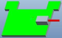
With the continuous improvement of technology, the satellite structure has been gradually developed. The whole box-plate satellite structure is usually spliced into a prismatic (including cuboid) shape by flat plates, and is generally designed according to the division of platform cabin and cargo cabin. On this basis, the concept of satellite platform is formed to improve the versatility of satellite structure design [6]. The box-type satellite has a simple structure and a smooth and flat surface, which is suitable for the installation of on-board equipment [7]; in order to further reduce the weight of the base plate, the idea of integrated satellite design was developed. Based on the idea of integrated design, the camera support plate and the satellite cabin plate are not strictly separated. Both sides of the support plate can be installed with the optical and mechanical components of the camera, electronic equipment and other components of the satellite. The supporting plate has the functions of both the camera supporting plate and the satellite cabin plate [8]. The Overall structure of the satellite is shown in Fig. 1. How to uniformly load the satellite bearing plate is an engineering problem in the mechanical testing of the satellite structure.
The satellite cabin wall panel serves as a critical structural component for the satellite, primarily adopting a panel/honeycomb sandwich structure that integrates diverse embedded connectors. Its primary function is to support the diverse functional parts of the satellite [9]. The satellite’s bearing base plate contains numerous load-bearing points and the load scenarios are intricate. It is crucial for mechanical testing to accurately replicate each operating condition to ensure overall reliability of the system. The current method of mechanical testing involves designing tests one by one to correspond with each working condition for serial operation. This approach’s advantage is precise assessment of each test condition. However, different working conditions entail different loading positions, leading to uneven stress that deforms the base plate’s mounting hole. This deformation negatively impacts subsequent mechanical tests. The timely launch of stars is crucial, necessitating efficient testing of aerospace structural mechanics. However, this mechanical testing methodology serves no advantage in addressing the challenge of uniform loading for large-scale satellite base plates.
In order to enhance the accuracy of mechanical testing, a test methodology comprising of three fundamental units has been put forward. The methodology efficiently ensures uniform loading of the complete satellite base plate through coordinating and connecting lever systems. Validation of the methodology’s reliability has been accomplished by comparing the satellite base plate’s structural testing and simulation results.
Fig. 1Overall structure of satellite
3. Design of multi-directional high stability test technology for load in the same plane
The benefit of the multi-directional high stability test technology in the same plane is that throughout the mechanical testing of the satellite, it guarantees that each loading direction of the loading base plate in the same plane operates synchronously without interference. The loading prerequisites are achieved via various unit combinations.
Based on the load application characteristics and base plate stress form, local stress in the base plate presents a typical multi-point uniformly distributed loading problem in the same plane. This study will provide a comprehensive overview of multi-point in-plane and multi-directional high stability test technology as applied to the mechanical testing of the entire satellite structure.
The stress load is divided into units, which are classified into units according to the different installation positions and the stress forms of the base plate under different test conditions. According to the actual situation, the special tooling for the test can be divided into three units: Unit 1, unit 2 and unit 3. As shown in Fig. 2, each unit is composed of a base plate and an adapter block connected with the load-bearing base plate.
Fig. 2Different loading units
a) Unit 1
b) Unit 2
c) Unit 3
The base plate is made of duralumin (2a12/t4), and the connecting block tooling is made of 45# steel. The material mechanical parameters are shown in Table 1.
Table 12a12/t4 material parameters
Name | / GPa | 0.2 %σs | |
2A12/T4 | 76 | 470 MPa | 255 MPa |
45# | 200 | 600 MPa | 355 MPa |
Taking a safety factor of 2 into consideration, the formula for calculating the allowable stress of the bottom plate tooling is as follows:
Take the safety factor of 2 [10] into account when calculating the allowable stress of the adapter block, using the following formula:
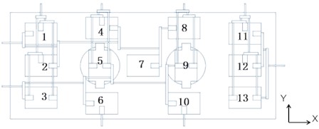
The aim of the multi-point, same-plane, and multi-directional high stability test technology design is to handle diverse forms of loads during the testing procedure, while offering specific treatment according to distinct base plate loads. Special tooling is categorized into distinct units and groups to accommodate varied load directions. The units, namely Unit 1, Unit 2, and Unit 3, are divided based on the tooling’s transfer methods and purposes. The test loading unit’s layout is depicted in Fig. 3 and Fig. 4. The load mounting base plate surrounds Unit 1, the circular hole of the load loading base plate positions Unit 2, and Unit 3 is located in the center of the load loading base plate.
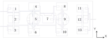
The test conditions consist of synchronous loading from multiple directions onto a base plate loaded with 13 uniformly distributed positions. The multi-directional stress on the base plate is achieved through the following combination method.
The lateral thrust loading force is accomplished through three units. As indicated in Fig. 4, the labeling sequence is 11-13. The right lever system breaks down the pushing force and distributes it evenly across the right load loading plate. The pulling force is attained through the collaboration of ten units, labeled 1-10 in Fig. 4. The center 7 is responsible for transferring the force from the top 8 on its right side to 4, following the principle of lever system distribution, which eventually combines at 1 and 2 to bear the tensile load. Similarly, 9 and 10 transfer their force to 5 and 6 according to the lever system distribution principle, which is then transferred to 2 and 3 for tension synthesis. The actuator is used for the application of the closing force.
The longitudinal thrust is achieved by connecting the actuator cylinder to the transfer lever through lower marks 6 and 10. The pulling force is divided into four groups: 1-3 belongs to group 1; 4-6 belongs to group 2; 8-10 belongs to group 3; and group 11-13 belongs to group 4. Transfer levers are stationed within each group. The pulling force is combined on the side of the load loading base plate using the principle of lever force system distribution, with the actuator linked to facilitate loading.
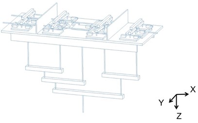
The force is produced using a system of levers consisting of two layers, illustrated in Fig. 3. In groups 1 to 4, vertical beams that bear loads are positioned above loading unit 3. The total number of vertical forces is 5. Using the lever force system’s distribution principle, a vertical force is synthesized and loaded by the loading actuator. The lever system is connected using a static connection as it deals with less force in the direction compared to the and directions. Despite offering less protection from sudden damage, this type of connection is not easily affected by external forces, and does not generate self-stress.
The tooling loading plate and load mounting base plate for the lateral force loading test use precise positioning to limit movement and rotation in , , and directions. They are connected in a very strong way. This design ensures the forces and stress are evenly spread out, making the structure extremely resilient. After removing unnecessary restrictions, the structure can still maintain its geometric shape [11].
Fig. 3Unit layout method
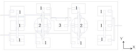
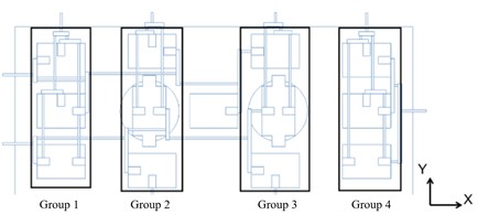
Fig. 4Principles of mechanical loading
4. Calculation and analysis of local structure of a satellite body
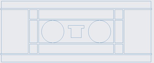
To confirm the trustworthiness of the previous experiment’s loading method, we analysed the structural mechanics of a satellite base plate. There are two approaches to studying static strength in structures – analysis and experimentation – which complement each other. The results from the experiment can form the foundation for the structure’s strength performance and provide data to establish precise analysis models [12]. The primary aim of analyzing mechanical tests beforehand is to prove that the simplified load can mimic the actual load of the structure properly. This ensures that the test reflects the actual stress situation of the structure, and enables successful verification of the structure [13]. The Fig. 5 shows the local structure of the mounting base plate used to load a Satellite.
Fig. 5Local structure of the mounting base plate
The structural plates of satellite structures comprise carbon fibre aluminium honeycomb plates, composed of isotropic material. The primary purpose of the panel is to supply the axial bending and in-plane shear stiffness needed to endure axial bending and in-plane shear loads. Its inner sandwich contains an assortment of heterogeneous materials. [14]. The panel’s elastic modulus is greatest along the fiber direction, while its Poisson’s ratio is greatest along the direction. The shear modulus values remain predominantly consistent for and , which are perpendicular to the fiber direction. However, the shear modulus for , which is perpendicular to the fiber direction, is small in value. The panel’s primary purpose is to provide axial bending and in-plane shear stiffness through its shear modulus to resist axial bending and in-plane shear loads [15]. Table 2 displays the precise material characteristics of both the skin and honeycomb sandwich structure. For dimensions of the loaded base plate, please refer to Table 3.
Table 2Material parameters of composite base plate
Carbon-brazed skin | |||||||||
Thickness / mm | Density / g/m2 | Poisson’s ratio | Young’s modulus / GPa | ||||||
0.6 | 1.7X10⁻⁹ | 0.3 | 50 | ||||||
Foam sandwich structure | |||||||||
Modulus of elasticity | Frictional coefficient | Shear modulus | |||||||
E1 | E2 | E3 | Nu12 | NU13 | NU23 | G12 | G13 | G23 | |
0.752 | 0.752 | 1165 | 0.8 | 0.004 | 0.003 | 0.186 | 260 | 260 | |
Table 3Dimension table for satellite loading installation base plate
Name | Long | Wide |
loading installation base plate | 3200 mm | 1300 mm |
The assessment of the entire mounting base plate for the satellite load requires it to withstand the pressure from , , and based on its stress properties. For experimental pre-analysis, this paper selects the worst case 2. The load base plate bears the force from both the and directions in this stress pattern with a high load series and complex deformation. Table 4 illustrates the fundamental mechanical characteristics of the composite honeycomb aluminium plate.
Table 4Mechanical parameters of honeycomb aluminum plate
/ GPa | 0.2%σs | |
70 | 130 MPa | 80 Kg/mm3 |
Table 5Load table of test case 2
Load level | (N) | (N) |
1 | 19206.135 | 7271.4 |
2 | 20103.57 | 7594.8 |
3 | 21001.005 | 7918.2 |
4 | 21898.44 | 8241.6 |
5 | 22795.875 | 8565 |
6 | 23693.31 | 8888.4 |
7 | 24590.745 | 9211.8 |
8 | 25488.18 | 9535.2 |
9 | 26385.615 | 9858.6 |
10 | 27283.05 | 10182 |
Boundary conditions involve a fixed and restrained center hole, with loads borne in both and directions on both sides of the base plate. For the pre-calculation and analysis of mechanical tests on the satellite base plate, the actual size of the aluminum honeycomb structure is modelled, and the skin size is simplified as a plate element. The base plate and vertical plate frame are fixed and rigidly connected to the lower frame. The skin is partitioned using quadrilateral elements (S4R) and triangular elements (S3), while the honeycomb is partitioned using tetrahedral elements (c3d4). This division results in 266381 nodes and 1359065 elements. Notably, the centre hole of the base plate is fixed, and its two sides bear the responsibility of and force loading. After compression, it is necessary to check whether the stress along the fibre direction and perpendicular to it meets the requirements [16], due to plastic deformation of the core. The local maximum total deformation value of the entire satellite simulation is considered the deformation value. For evaluation, select level 10-20 load in case 2, of which level 20 serves as the base plate identification load. The load size is presented in Table 5. Details of load simulation calculation of load mounting base plate are demonstrated in Fig. 6.
Fig. 6Boundary conditions of finite element analysis of base plate
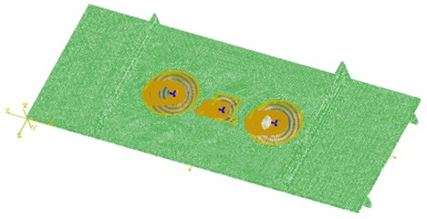
Fig. 7Strain in finite element simulation
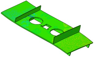
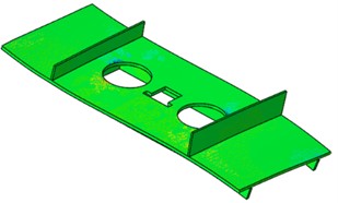
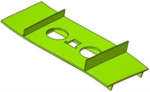
Fig. 8Displacement of finite element simulation
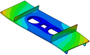
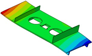
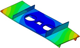
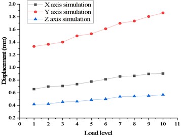
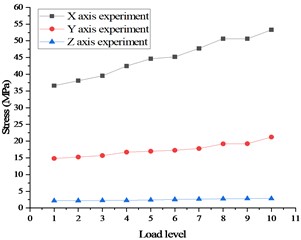
The simulation results demonstrate that subsequent to the mechanical loading of the entire satellite base plate, the deformation and stress of the base plate skin in three directions fall within the allowable range of the material under the most severe working case. Furthermore, the central honeycomb sandwich incurs substantial stress at the corners, consistent with the actual stress situation. As the number of loading stages increases in a gradual manner, the linear relationship remains consistent, as demonstrated in Fig. 9 and Fig. 10.
Fig. 9Maximum stress curve in case 2
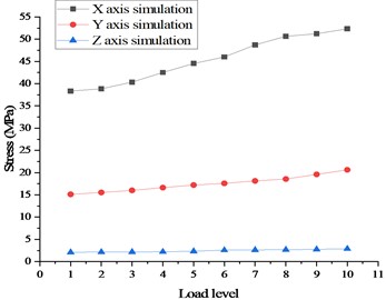
Fig. 10Maximum displacement curve in case 2
5. Whole satellite stress mechanical loading test
A mechanical loading test examines the stress and strain distribution of a specimen under static load to confirm the mechanical strength of the specimen structure [17]. Utilizing this uniform loading technology, a structural mechanical test of a satellite was performed. The DH3817F data acquisition system was used during testing. Joint evaluation uncertainty yielded 0.1 % (2). The YHD-30 model was utilised and its basic error had a value of 0.02 mm. The force sensor load display accuracy error was 0.2 %-0.5 %. Strain measuring points are detailed in Table 6, while the Fig. 11 layout illustrates test point placement on the entire satellite load mounting base plate.
Fig. 11Location of strain measurement points for whole satellite mechanical test
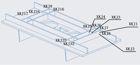
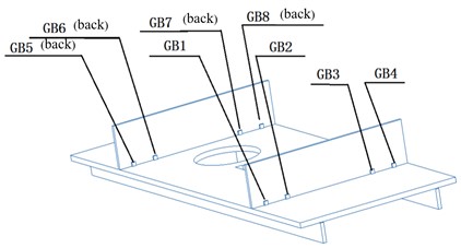
Table 6Description of strain measuring points
Name of measuring point | Illustrate | Total number of channels |
XKJ | Strain flower of lower frame assembly | 42 |
GB | Strain flower of diaphragm | 24 |
The strain gauges are located primarily at the frame and diaphragm positions throughout the entire mechanical testing process of the satellite. This includes a total of 40 three-way strain gauges and 120 testing channels. The strain gauge specifications are BE120-3CA, with a sensitivity coefficient of 2.2±1 %. The frame and base plate are securely joined, and the lower frame and vertical plate possess the presence of strain gauges. The primary purpose is to detect the frame’s deformation after the load has been installed on the base plate, enabling the acquisition of the base plate’s deformation.
Fig. 12Installation state of loading plate during test
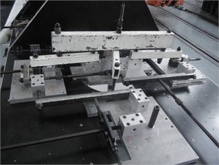
Each unit is firmly attached and fastened to the load loading base plate via screw connection, utilizing a tightening torque of 4.5 N·m. The units are linked by screws. The ultimate resultant force loading point is taken out from the opening position. Two pulling forces are led out in the direction, one pushing force is led out, two pushing forces are led out in the direction, and two pulling forces are led out to complete the load loading, as demonstrated in Fig. 12. As the test value of levels 0-14 is small, it has been omitted. The stress and displacement test data are presented in Table 7, Table 8 and Table 9.
Table 7Displacement test data
15 | 16 | 17 | 18 | 19 | 20 | 0 | |
XKJ24 | –54.89 | –57.14 | –59.19 | –61.58 | –63.55 | –65.96 | –0.09 |
XKJ17 | –54.09 | –56.11 | –58.59 | –60.82 | –75.40 | –77.92 | 0.12 |
XKJ18-45° | –62.27 | –64.76 | –67.17 | –69.76 | –60.21 | –62.16 | –0.17 |
XKJ20-45° | –49.19 | –51.17 | –53.07 | –55.05 | –57.20 | –59.09 | 0.09 |
GB8 | –46.31 | –48.20 | –59.99 | –52.10 | –64.94 | –55.81 | 0.27 |
XKJ9-45° | –40.17 | –41.52 | –43.37 | –44.72 | –46.22 | –57.23 | 0.17 |
XKJ23 | –37.36 | –38.81 | –40.23 | –41.97 | –43.17 | –44.91 | –0.12 |
XKJ10 | –39.26 | –38.88 | –40.35 | –41.26 | –39.80 | –41.45 | –1.28 |
GB7 | –31.59 | –32.95 | –34.28 | –35.61 | –36.78 | –38.17 | 0.19 |
XKJ16-45° | –30.71 | –31.79 | –33.06 | –34.44 | –35.60 | –37.00 | 0.24 |
XKJ18 | –30.68 | –31.92 | 33.04 | –34.40 | –35.30 | –36.78 | –0.01 |
XKJ15 | –28.33 | –35.57 | –30.54 | –31.80 | –39.94 | –41.18 | 0.05 |
Table 8Displacement test data
15 | 16 | 17 | 18 | 19 | 20 | 0 | |
XKJ2-45° | 77.71 | 68.06 | 83.86 | 73.43 | 76.08 | 93.70 | 0.29 |
XKJ8 | 55.63 | 68.90 | 60.26 | 62.34 | 64.42 | 79.53 | 1.08 |
GB1 | 53.87 | 66.46 | 58.83 | 71.70 | 74.07 | 64.56 | 2.09 |
XKJ1 | 45.55 | 47.49 | 49.39 | 51.48 | 52.87 | 65.50 | 0.42 |
XKJ4-45° | 39.20 | 40.84 | 50.51 | 52.14 | 45.43 | 47.06 | 0.65 |
XKJ32-45° | 40.06 | 40.73 | 35.50 | 37.57 | 38.68 | 47.52 | –0.05 |
XKJ7 | 32.82 | 33.91 | 41.85 | 36.64 | 37.90 | 39.28 | 0.82 |
XKJ25-45° | 38.08 | 33.46 | 40.91 | 36.03 | 44.03 | 45.87 | 0.66 |
XKJ26 | 30.36 | 37.36 | 39.02 | 34.08 | 35.15 | 36.46 | 0.02 |
GB2 | 29.14 | 30.14 | 31.56 | 32.58 | 33.84 | 41.58 | 0.00 |
Table 9Stress test data
Load level | 15 | 16 | 17 | 18 | 19 | 20 | 0 |
1X [mm] | –0.01 | –0.02 | –0.02 | –0.03 | –0.04 | –0.05 | –0.05 |
1Y [mm] | –0.08 | –0.09 | –0.1 | –0.1 | –0.12 | –0.12 | –0.08 |
4X [mm] | –0.05 | –0.05 | –0.06 | –0.06 | –0.07 | –0.07 | –0.04 |
4Y [mm] | 0.16 | 0.17 | 0.18 | 0.19 | 0.2 | 0.21 | 0.03 |
2X [mm] | 0 | 0 | 0 | 0 | 0 | 0 | 0 |
2Y [mm] | –0.01 | –0.02 | –0.03 | –0.03 | –0.04 | –0.05 | 0 |
3X [mm] | 0.05 | 0.06 | 0.06 | 0.06 | 0.07 | 0.08 | 0.01 |
3Y [mm] | –0.1 | –0.09 | –0.09 | –0.09 | –0.09 | –0.1 | 0 |
X [mm] | 0 | 0 | 0 | 0 | 0 | 0 | 0 |
Y [mm] | –0.08 | –0.09 | –0.1 | –0.1 | –0.1 | –0.1 | –0.02 |
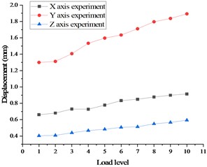
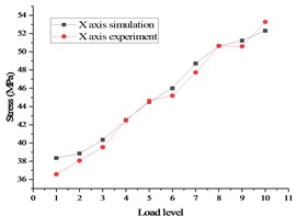
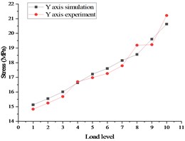
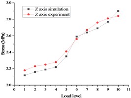
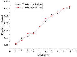
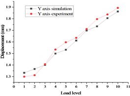
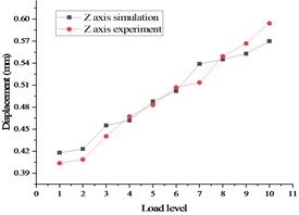
The final stress and deformation values from the test are displayed in Fig. 13, with the stress test results on the left side and the displacement test results on the right side. A comparison between the pre-calculation results and the test data is demonstrated in Fig. 14, with the stress comparison diagram on the left side and displacement comparison diagram on the right side.
Fig. 13Stress and displacement of whole satellite mechanical test in case 2
For the goodness of fit index of non-linear regression, with the same number of parameters, a smaller distance between the test value and simulation value indicates a better fitting degree. The relevant literature provides the formula:
The auxiliary index for a good fit is:
FR is determined by the angle cosine function, with a smaller indicating superior fitting. As the RNL value approaches 1, the linear correlation improves [18], [19]. In this study, a mechanical uniformly distributed loading test method was employed, resulting in a final RNL value of 1.298 and an FR value of 0.945, indicating strong goodness of fit. The test results exhibit a linear correlation with the simulation findings. During testing, the most severe stress deformation occurs at the junction where the and meet. The test data demonstrate a linear relationship which aligns with the pre-calculated results.
Fig. 14Comparison of stress and displacement test and Simulation of whole satellite mechanical test in case 2
6. Conclusions
To address the issue of uniform loading in mechanical tests of box plate satellites, a high-stability test technology in the same plane is proposed, which involves multiple directions. This method’s reliability is confirmed through a comparison of the test data with simulation results.
1) It is important to fully consider load distribution in the test design. The various load types in different operational settings are carefully classified, and then assigned to relevant units after unitization to ensure the force’s scientific validity.
2) Additionally, when performing mechanical environment tests, one must fully account for the interaction between the testing specimen and the tools employed. This test method transfers the load from the lever system onto the test piece. This reduces the impact of tooling deformations on strain measurement data, leading to improved accuracy of the test.
3) Additionally, this method resolves the issue of uniform loading of the satellite base plate in the same plane during mechanical testing. Simultaneously, the ongoing refinement of the satellite structure renders this testing methodology a valuable resource in addressing the issue of evenly distributing loads over multi-layered structures.
References
-
S. Ramayanti, P. A. Budiantoro, A. Fauzi, E. Fitrianingsih, and E. N. Nasser, “comparative study of deployable satellite solar panel structure between carbon fiber reinforced polymer and Al-7075 honeycomb,” in IEEE International Conference on Aerospace Electronics and Remote Sensing Technology (ICARES), pp. 1–6, Nov. 2022, https://doi.org/10.1109/icares56907.2022.9993517
-
R. H. Morais, L. F. F. M. Santos, A. R. R. Silva, and R. Melicio, “Dynamics of a gyrostat satellite with the vector of gyrostatic moment tangent to the orbital plane,” Advances in Space Research, Vol. 69, No. 11, pp. 3921–3940, Jun. 2022, https://doi.org/10.1016/j.asr.2022.03.004
-
Q. Q. Peng et al., “Progress and prospect of spacecraft configuration reconstruction technology,” (in Chinese), Chinese space science and technology, Vol. 43, No. 2, pp. 16–31, 2023, https://doi.org/10.16708/j.cnki.1000-758x.2023.0017
-
H. Zhu et al., “A method of static test for thin-walled central cylinder using dispersive loading,” (in Chinese), Spacecraft Engineering, Vol. 24, No. 5, pp. 144–150, 2015, https://doi.org/10.3969/j.issn.1673-8748.2015.05.022
-
Q. F. Yang, X. J. Tang, and Z. G. Yan, “Simulation and verification of high uniform load boundary for the static test of plate pattern structure,” (in Chinese), Manufacturing automation, Vol. 43, No. 11, pp. 111–113, 2021, https://doi.org/10.3969/j.issn.1009-0134.2021.11.025
-
S. Yaoxing, Y. Hang, J. Zongxia, and Y. Nan, “Matching design of hydraulic load simulator with aerocraft actuator,” Chinese Journal of Aeronautics, Vol. 26, No. 2, pp. 470–480, Apr. 2013, https://doi.org/10.1016/j.cja.2013.02.026
-
B. Meng et al., “Simulation and optimization of equipment layout for aircraft structure production line,” (in Chinese), Machinery Design and Manufactur, pp. 222–228, 2023, https://doi.org/10.19356/j.cnki.1001-3997.2023.01.029
-
Q. H. Xu et al., “Remote sensing satellite platform and payload integrated configuration,” (in Chinese), Spacecraft Recovery and Remote Sensing, Vol. 35, No. 4, pp. 9–16, 2014, https://doi.org/10.3969/j.issn.1009-8518.2014.04.002
-
Y. X. Yin and H. P. Li, “Applications of Advanced resin matrix composites for use in Chinese spacecraft,” (in Chinese), Spacecraft Recovery and Remote Sensing, Vol. 39, No. 4, pp. 101–108, 2018, https://doi.org/10.3969/j.issn.1009-8518.2018.04.013
-
Hao P. et al., “A precise design method for structural safety factor considering load,” (in Chinese), Journal of Mechanical Engineering, Vol. 2024, 2024.
-
F. Sun, R. B. Gramacy, B. Haaland, E. Lawrence, and A. Walker, “Emulating satellite drag from large simulation experiments,” SIAM/ASA Journal on Uncertainty Quantification, Vol. 7, No. 2, pp. 720–759, Jun. 2019, https://doi.org/10.1137/18m1170157
-
G. W. Hein, “Status, perspectives and trends of satellite navigation,” Satellite Navigation, Vol. 1, No. 1, Aug. 2020, https://doi.org/10.1186/s43020-020-00023-x
-
Q. Fu, Z.-W. Cao, X.-D. Liao, Y.-N. Liu, and S.-Q. Zhang, “Quasi-static test and simplified analysis method of a new type precast shear wall with unconnected vertical distributed reinforcements,” Journal of Building Engineering, Vol. 47, p. 103794, Apr. 2022, https://doi.org/10.1016/j.jobe.2021.103794
-
Wo X. Y., Xia Y. W., and Tu B., “The property of honeycomb sandwich structure and the destroy mode analyzing,” Spacecraft Recovery and Remote Sensing, Vol. 2005, No. 4, pp. 45–49, 2005, https://doi.org/10.3969/j.issn.1009-8518.2005.04.009
-
J. Peng et al., “Design and Optimization of Thin-Walled Main Support Structure for Space Camera Based on Additive Manufacturing,” Micromachines, Vol. 15, No. 2, p. 211, Jan. 2024, https://doi.org/10.3390/mi15020211
-
F. Jiang, S. Yang, C. Ding, and C. Qi, “Quasi-static crushing behavior of novel circular double arrowed auxetic honeycombs: Experimental test and numerical simulation,” Thin-Walled Structures, Vol. 177, p. 109434, Aug. 2022, https://doi.org/10.1016/j.tws.2022.109434
-
H.-G. Kim, S. Kim, H.-K. Choi, S.-H. Hong, and S.-H. Kim, “Structural Static Test for Validation of Structural Integrity of Fuel Pylon under Flight Load Conditions,” (in Korea), Journal of Aerospace System Engineering, Vol. 16, No. 1, pp. 97–103, Feb. 2022, https://doi.org/10.20910/jase.2022.16.1.97
-
B. Xing, F. Tang, C. Song, and X. He, “Static and fatigue behavior of self-piercing riveted joints with two overlap areas,” Journal of Materials Research and Technology, Vol. 14, pp. 1333–1338, Sep. 2021, https://doi.org/10.1016/j.jmrt.2021.07.064
-
B. Zang, B. Zhang, Y. Liu, G. Zhou, H. Yan, and Y. Hou, “Research on strain testing method and accuracy evaluation of spacecraft in heat and force field,” Science Progress, Vol. 107, No. 2, p. 368504241259375, Jun. 2024, https://doi.org/10.1177/00368504241259375
About this article

The authors have not disclosed any funding.
The datasets generated during and/or analyzed during the current study are available from the corresponding author on reasonable request.
Liu Yuhan: conceptualization, writing-original draft preparation. Zhou Guodong: formal analysis. Liu Yuhang: methodology. Zhang Baokang: resources. Gao Zheng: software. Yan Huyi: validation.
The authors declare that they have no conflict of interest.
