Abstract
To fully evaluate the influence of the rough surface (σ) and speed (ω) of the crankpin bearing on the engine power, a combination model of the slider crank mechanism and crankpin bearing’s lubrication is established to calculate the mathematical equations for the simulation. Three indexes of the bearing-capacity (W), friction-force (F), and friction-coeficient (μ) are used to evaluate the influence of the change of the crankpin bearing’s speed and rough surface on the engine’s power. The study shows that increasing ω not only effectively reduces the load capacity of the crankpin bearing but also increases the F and μ in the engine’s crankpin bearing, thereby directly reducing the engine’s power. Besides, the reduction of ω also reduces the bearing-capacity of the crankpin bearing. To optimize the engine’s power, the engine’s speed should be maintained at 2000 r/min to improve the engine’s power. In addition, under the effect of the rough surface of the crankpin bearing, the W of the crankpin bearing is insignificantly affected by the change of the rough surface while both the F and μ are greatly affected. In particular, the maximum F at σ = 8 μm and σ = 10 μm is increased by 68.3 % and 77.7 % in comparison with the maximum F at minimum value of σ = 2 μm, respectively. Therefore, in the design of the engine, the rough surface of the crankpin bearing should be reduced to improve the engine’s power. Additionally, the design parameters of the crankpin bearings should also be optimized to further improve the engine’s power.
1. Introduction
Given greater demands to reduce environmental pollution of automobiles, technologies that can reduce the friction forces to enhance the internal combustion engine’s power are concerning and developing [1, 2]. Studies on the influence of the various design parameters of the slider crank mechanism, the inertial mass of the piston, and the eccentricities of the cylinder center and crankshaft center of the engine have been carried out over the last few decades [3-5]. The vibrations and noises generated by the friction forces between the cylinder and piston could significantly be reduced by optimizing the structure of the slider crank mechanism. Optimization studies have also investigated the characteristics of lubrication factors, such as the friction-force (F) and friction-coeficient (μ), between two slip/nonslip surfaces of the engine’s cylinder-piston and [2, 5-6]. Researchers have found that the engine’s friction force is strongly decreased in the case of the oil film existing on the two slip/nonslip surfaces of the engine’s cylinder-piston.
Besides, the engine’s friction force is also strongly affected by the two slip/nonslip surfaces of the engine’s crankpin bearing. The lubrication model of crankpin bearings under an external load acting on the shaft moving at high speed was previously studied to evaluate the effect of the oil film thickness (h) on the engine’s friction force [7-9] according to the evaluation indices of the bearing-capacity (W) and F. Results showed that the stability of h is decided by the film pressure existing in the crankpin bearing. The influence of the oil film’s temperature [10], load, and radial gap [7, 12-13] on the pressure of the lubrication oil film has also been analyzed [7-8, 12]. Moreover, to improve engine power, during the manufacturing process of bearings, advanced diagnostic methods based on machine learning technology or using neural networks have been researched and applied to detect and find faulty bearings that directly affect the durability of the bearings [14-20]. In the above studies, the scholars mainly assessed the lubrication efficiency of the crankpin bearing under the condition of a static load on a shaft moving at high speed. In actual applications, the resistance of the oil film could be affected by its shear stress generated under the crankpin bearing’s various speeds and rough surfaces between the shaft and bearing surfaces.
In addition, the dynamic load of the slider crank mechanism acting on the crankpin bearing changes quickly under various engine speeds in terms of direction and intensity when the internal combustion engine is working [3, 4]. These phenomena, to some extent, may aggravate the influence of the micro asperity contact in the mixed-lubrication regime on the tribological properties of the crankpin bearing and reduce the engine’s power when the engine’s speed is changed. Therefore, the effects of the rough surface of the crankpin bearing surfaces and the engine’s speed should be taken into account during analyses of the engine power. However, investigations on the engine power considering both the rough surface and speed of the crankpin bearing have rarely been reported.
The current study establishes a study approach by coupling the slider crank mechanism and lubrication model of the crankpin bearing to evaluate the effect of the rough surface of the crankpin bearing surfaces and the engine’s speed on the engine power. An algorithm program based on the hybrid model was developed in MATLAB to solve these issues. Three indexes of the W, F, and friction-coeficient (μ) are used to evaluate the influence of the change of the crankpin bearing’s speed and rough surface on the engine’s power.
2. Slider crank mechanism’s dynamic model
Based on the actual structure of an engine, the slider crank mechanism’s dynamic model could be established as shown in Fig. 1, where L and R the connecting rod length and rotation radius of the crankshaft, respectively. P is the combustion gas pressure acting on the piston peak. N and Fc are the piston forces impacting on the cylinder wall and connecting rod, respectively. F is the total force of the piston. Fic, Fc1, and Fc2 are the forces of the slider crank mechanism impacting the crankpin bearing. W0 is the acting force on the crankpin bearing. ϕ and ω are the respective angle and angular velocity of the shaft.
Fig. 1Slider crank mechanism model and lubrication of crankpin bearing
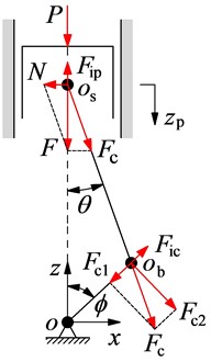
a) Slider crank mechanism
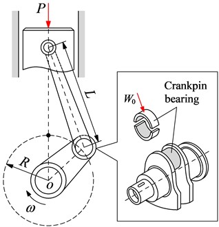
b) Crakpin bearing lubrication
The piston’s motion can be determined as:
With λ=R/L, therefore, the piston’s motion and acceleration can be written as follows:
¨zp=Rω2(cosϕ+λcos2ϕ)
where ω=˙ϕ=dϕ/dt. msc and mbc are assumed to be masses of small- and large-rod-ends at os and obof the connecting rod. Thus, the inertial force of small-rod-end and piston is written as:
where mb is the piston mass.
Under the effect of the combustion gas pressure acting on the piston peak, the dynamic force of Ncan be determined by:
Fc=Fcosθ=Fip+Pcosθ.
The impact of Fc, which has two components of tangential and radial forces, on the CB is:
Under the same angular velocity of the engine ω, the Ficcan be defined as:
The bearing of the connecting rod provides a rotating motion and transmits loads between the large-rod-end and crankpin. Thus, the load of the engine’s crankpin bearing is determined by:
Changes in W0 in both direction and intensity could be applied to calculate the engine power.
3. Crankpin bearing’s lubrication model
3.1. Lubrication model in the computational region
In the engine’s working process, the W0 always impacts the crankpin is of the crankpin bearing, and the crankpin is rotated with an angular velocity of ω inside the bearing of the connecting rod, as shown in the same Fig. 1. Therefore, the lubrication and friction of the crankpin bearing could be evaluated by modeling the crankpin under the impact of W0 and rotated at ω inside the bearing as shown in Fig. 2.
In Fig. 2, B and rb are the bearing width and radius, respectively. rs is the shaft radius and rs<rb; e and ε=e/c(0<ε<1) are the eccentricity and eccentricity ratio between the center of the bearing and shaft, respectively; c=rb-rs is the crankpin bearing’s gap fully filled with the lubricant to create the hydrodynamic pressure p; u0=ωrb is the velocity of the crankpin surface; ψ is the attitude angle.
The h can be determined from the crankpin bearing’s lubrication model as follows [21]:
Fig. 2Impact forces on the crankpin bearing under various angular speeds
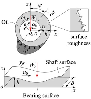
a) Lubrication model
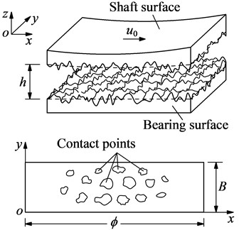
b) Rough surface and contact model
3.2. Lubrication equations of models
Assume that the bearing surface is fixed in the x direction and the y direction. The shaft surface moves in the x direction with the velocity u0, as seen in Fig. 2. Thus, the velocity condition of the oil film in the crankpin bearing is determined by:
The density and viscosity of the oil film are assumed to be unchanged in the working process of the engine, and the influence of the inertia of the lubricant flow on the working process is negligible. Thus, the equation of the lubrication film can be described as [13, 21-23]:
The dimensionless form of the Reynolds equation in Eq. (10) can be written as:
where Φ=x/rb,Y=y/B, H=h/c, P=p/p0, T=t/t0, u0=ωrb, Λ1=6ηωB2/p0c2, Λ2=12ηB2/t0p0c2, β=B/rb, Γ=σ/c, p0=101325 Pa is the standard atmospheric pressure, σ is the rough surface of the crankpin bearing, η is the dynamic viscosity of the oil.
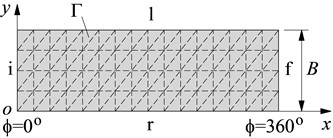
The boundary conditions must be determined to calculate the p over the computational domain of Eq. (11). In this study, we assume that h exists over the surface of the crankpin bearing and the area of the computation domain is Γ, as plotted in Fig. 3. Where i and f are the respective boundary lines of the initial pressure and final pressure at the maximum position of h with ϕ=0° and 360°. r and l are the respective boundary lines of the right and left pressures of the bearing at y=0 and B.
Therefore, the boundary conditions of the oil film pressure can be written as:
By combining Eq. (11) and Eq. (12), the p and h of the crankpin bearing’s oil film can be calculated.
Fig. 3Computational region of crankpin bearing
3.3. Lubrication forces of mixed hydrodynamics of crankpin bearing
Under the impact of W0 on the crankpin bearing, the W generated by the film pressure p in Γ is determined by [24-25]:
The friction force F of the crankpin bearing generated from the interaction shear stress acting on the shaft in Γ can be calculated by [12]:
where τis is the interfacial shear stress. τac is the asperity contact stress between the two surfaces of the crankpin and bearing. They were calculated by [12]:
where τ1 and τ2 are the inter-fluid shear stress and shear stress of the fluid acting on bumpy peaks, respectively, τ0 and μ0 are the shear stress and boundary friction coefficients.
When W and F are obtained, the μ of the engine’s crankpin bearing can be given by [23]:
In this study, the W, F, and μ are used as indices to evaluate the engine’s power.
4. Simulation results and analysis
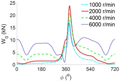
The necessary parameters for simulation listed in Table 1 and the combustion gas pressure acting on the piston peak, which is obtained from the experimental data in Ref. [12], as shown in Fig. 4(a), were used for calculating the W0 under various ω and analyze the engine’s lubrication and friction. The W0 results have been shown in Fig. 4(b).
As shown in Fig. 4(b), the impact load is constantly varied under different ω and rotation angles. The maximum value of W0 is obtained at 2000 r/min while the minimum value of W0 is obtained at 6000 r/min in a range of ϕ from 350° to 420°. However, outside of the rotational angles of 350° to 420°, the maximum value of W0 is obtained at 6000 r/min. This finding may be attributed to the influence of the change of the ω in Eq. (6). Therefore, to evaluate the effect of the engine’s speed on the lubrication and friction of the crankpin bearing, a change range of ω from 1000 r/min to 6000 r/min has been simulated in Section 4.1.
Table 1Simulation parameters of the slider crank mechanism and crankpin bearing
Parameters | Values | Parameters | Values | Parameters | Values |
mp (kg) | 0.264 | B (mm) | 20 | p0 (kPa) | 101.325 |
mbc (kg) | 0.345 | rb (mm) | 25 | ϕ (o) | 0-720 |
msr (kg) | 0.095 | L (mm) | 129.5 | c (μm) | 10 |
mbr (kg) | 0.250 | R (mm) | 40 | η (Pa·s) | 0.02 |
Fig. 4Impact forces on the crankpin bearing under the engine’s various angular speeds
a) Experimental combustion gas pressures
b) Impacting forces of W0
4.1. Effect of engine speed
The moving speed between the two slip/nonslip surfaces of the crankpin bearing is calculated by u0=ωrb. Thus, the different speeds of ω of 1000 r/min, 2000 r/min, 4000 r/min, and 6000 r/min with their W0 in Fig. 4(b) are simulated and computed to evaluate the W, F, and μ of the engine’s crankpin bearing.
Fig. 5Oil film pressure and shear stress at 2000 r/min
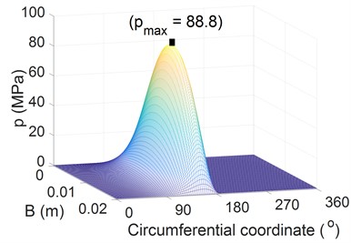
a) Pressure of the oil film
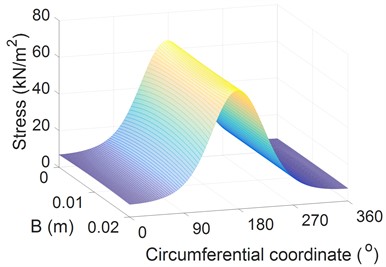
b) Shear stress of the oil film
The simulation results of the distributions of the p and τ on the surface of the crankpin bearing under different W0 at 2000 r/min are shown in Figs. 5(a) and 5(b). The p values are mainly distributed over the range of 90° to 180° with B, and the maximum p at 158° is 88.8 MPa. This finding is identical to the results presented in Refs. [2, 12, 23]. The shear stress τ is also uniformly distributed along B. However, in the circumferential direction, the shear stress τ remarkably varies and peaks at 178°.
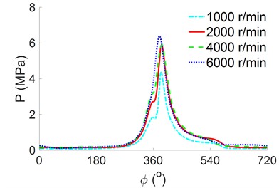
The distributions of the p and τ at a bearing width of B/2 under different angular speeds of ω are illustrated in Figs. 6(a) and 6(b). The result in Fig. 6(a) indicates that the p greatly depends on both the values of W0 and ω. The maximum and minimum pressures corresponding to W0 are also obtained at 2000 r/min and 6000 r/min. Conversely, the result in Fig. 6(b) shows that the τ only depends on the angular speeds of ω, the τ increases with increasing ω and vice versa.
Fig. 6Distributions of the p and τ at a bearing width of B/2 under different angular speeds
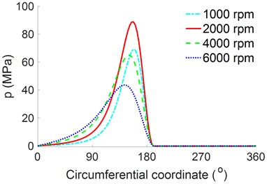
a) Pressure of the oil film
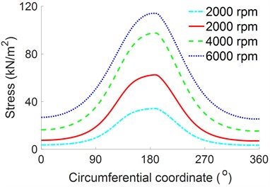
b) Shear stress of the oil film
Fig. 7Effect of the speed on the engine’s power
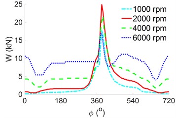
a) The result of W
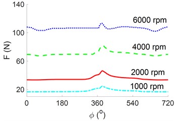
b) The result of F
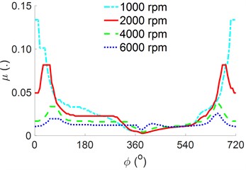
c) The result of μ
From the data of the p and τ at the different speeds of the engine in Figs. 6(a) and 6(b), the W, F, and μ of the engine’s crankpin bearing are computed and plotted in Figs. 7(a), 7(b), and 7(c), respectively. The W shown in Fig. 7(a) is similar to W0 in Fig. 4(b) under various values of ω because the pressure of the oil film varies to satisfy that W is equivalent W0. Fig. 7(b) reveals that the F increases sharply with increasing ω. Moreover, the F peaks at a high ω of 6000 r/min, which means the F impacting on the crankpin bearing is greatest at the speed of 6000 r/min. This result may be due to the increase in the slip speed between the shaft and bearing surface, which increases the lubrication film’s friction value. Fig. 7(c) presents the μ of the crankpin bearing. The values of μ change with the variation of W and F and decrease with increasing ω. The results of the W, F, and μ in Figs. 7(a), 7(b), and 7(c) show that when ω is maintained at 2000 r/min, W0 peaks, but both the values of F and μ remain relatively small. This means that the engine’s load capacity is increased while the engine’s friction is reduced. Thus, this is also a reason that most engines should work at this speed [2, 5].
4.2. Effect of surface roughness
The change of the rough surface of the crankpin bearing with σ = 2 μm, 4 μm, 6 μm, 8 μm, and 10 μm on the engine’s tribological properties under the same conditions of a load W0 at 2000 r/min is also evaluated. The simulation results of the p and τ at a bearing width of B/2 under different surface roughness values are shown in Figs. 8(a) and 8(b).
Fig. 8Distributions of the p and τ at a bearing width of B/2 under different surface roughness values
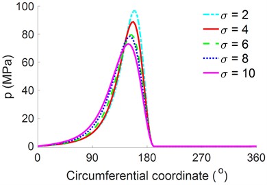
a) Pressure of the oil film
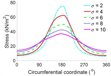
b) Shear stress of the oil film
Fig. 9Effect of the surface roughness on the engine’s power
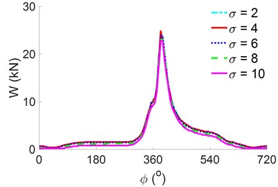
a) The result of W
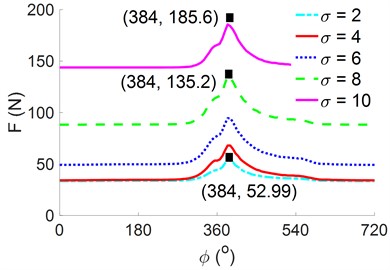
b) The result of F
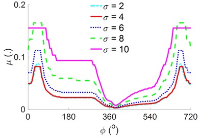
c) The result of μ
The result shows that both the p and τ increase with decreasing σ and vice versa. Thus, the surface roughness σ can affect the tribological properties of the engine’s crankpin bearing. This finding is further analyzed by plotting the results of the tribological properties of the W, F, and μ, as shown in Figs. 9(a), 9(b), and 9(c), respectively.
Both Figs. 9(a) and (b) reveal that the maximum W is unremarkably affected by the σ while the F remarkably increases with increasing σ, especially at σ = 8 μm and σ = 10 μm. This could be explained as follows. As the height of the surface roughness increases, the probability of solid contact in the asperity contact region of the surfaces of the crankpin bearing also increases, thereby increasing the pressure and stress of the asperity contact. The calculation result of the F indicates that the maximum F at σ = 8 μm and σ = 10 μm is increased by 68.3 % and 77.7 % in comparison with the maximum F at minimum value of σ = 2 μm, respectively. Thus, the resistance of the crankpin bearing may be concluded to be greatly affected by the friction force generated by the rough surface of the crankpin bearing.
An increase in surface roughness remarkably increases the contacts between the micro-convex peak and the friction generated between the solid contacts. Thus, the friction coefficient μ also increases with the F, as shown in Fig. 9(c). Therefore, to enhance the W and reduce both the F and μ to improve the engine’s power, the solid contacts between the two surfaces of the crankpin and bearing should be reduced. This means that the rough surface of the crankpin bearing should be reduced.
5. Conclusions
Increasing ω not only effectively reduces the load capacity of the crankpin bearing but also increases the friction force and friction coefficient in the engine’s crankpin bearing, thereby directly reducing the engine’s power. The simulation results show that the engine’s power can be improved better when ω is maintained at 2000 r/min.
Under the change of the rough surface of the crankpin bearing simulated and analyzed, the results show that the W of the crankpin bearing is insignificantly affected by the change of the rough surface while both the F and μ are greatly affected. In particular, the maximum F at σ = 8 μm and σ = 10 μm is increased by 68.3 % and 77.7 % in comparison with the maximum F at minimum value of σ = 2 μm, respectively. Thus, the rough surface of the crankpin bearing should be reduced to improve the engine’s power.
Improving the lubrication while reducing the friction of the engine is a challenging issue. Therefore, the present study not only contributes to the existing body of knowledge on the engine lubrication and friction of automotive engines but also provides an important reference for optimal design parameters to improve this engine property further.
Based on the research results, we also discovered that the design parameters of the crankpin bearings should also be optimized to further improve the engine’s power. Besides, adding microtextures to the bearing surface can also enhance the lubricating oil film and reduce contact friction generated between the two surfaces of the crankpin and bearing, thereby improving engine power. These issues can continue to be researched.
References
-
X. Meng, L. Ning, Y. Xie, and V. W. Wong, “Effects of the connecting-rod-related design parameters on the piston dynamics and the skirt-liner lubrication,” Proceedings of the Institution of Mechanical Engineers, Part D: Journal of Automobile Engineering, Vol. 227, No. 6, pp. 885–898, Nov. 2012, https://doi.org/10.1177/0954407012464025
-
B. Zhao, X.-D. Dai, Z.-N. Zhang, and Y.-B. Xie, “A new numerical method for piston dynamics and lubrication analysis,” Tribology International, Vol. 94, pp. 395–408, Feb. 2016, https://doi.org/10.1016/j.triboint.2015.09.037
-
K. Liu, Y. Xie, and C. Gui, “A comprehensive study of the friction and dynamic motion of the piston assembly,” Proceedings of the Institution of Mechanical Engineers, Part J: Journal of Engineering Tribology, Vol. 212, No. 3, pp. 221–226, 1998, https://doi.org/10.1243/1350650981542038
-
S.-H. Cho, S.-T. Ahn, and Y.-H. Kim, “A simple model to estimate the impact force induced by piston slap,” Journal of Sound and Vibration, Vol. 255, No. 2, pp. 229–242, Aug. 2002, https://doi.org/10.1006/jsvi.2001.4152
-
S. H. Mansouri and V. W. Wong, “Effects of piston design parameters on piston secondary motion and skirt – liner friction,” Proceedings of the Institution of Mechanical Engineers, Part J: Journal of Engineering Tribology, Vol. 219, No. 6, pp. 435–449, Jun. 2005, https://doi.org/10.1243/135065005x34026
-
N. Patir and H. Cheng, “Application of average flow model to lubrication between rough sliding surfaces,” Journal of Lubrication Technology, Vol. 101, No. 2, pp. 220–229, 1979.
-
A. Raj and P. Sinha, “Transverse roughness in short journal bearing under dynamic loading,” Tribology International, Vol. 16, No. 5, pp. 245–251, Oct. 1983, https://doi.org/10.1016/0301-679x(83)90081-6
-
X. Wang, J. Zhang, and H. Dong, “Analysis of bearing lubrication under dynamic loading considering micropolar and cavitating effects,” Tribology International, Vol. 44, No. 9, pp. 1071–1075, Aug. 2011, https://doi.org/10.1016/j.triboint.2011.05.002
-
G. Daniel and K. Cavalca, “Analysis of the dynamics of a slider-crank mechanism with hydrodynamic lubrication in the connecting rod-slider joint clearance,” Mechanism and Machine Theory, Vol. 46, No. 10, pp. 1434–1452, Oct. 2011, https://doi.org/10.1016/j.mechmachtheory.2011.05.007
-
H. Zhang, M. Hua, G.-N. Dong, D.-Y. Zhang, and K.-S. Chin, “Boundary slip surface design for high speed water lubricated journal bearings,” Tribology International, Vol. 79, pp. 32–41, Nov. 2014, https://doi.org/10.1016/j.triboint.2014.05.022
-
B. Zhao et al., “Modeling and analysis of planar multibody system with mixed lubricated revolute joint,” Tribology International, Vol. 98, pp. 229–241, 2016, https://doi.org/10.1016/j.triboint.2016.02.024
-
J. A. Greenwood and J. H. Tripp, “The contact of two nominally flat rough surfaces,” Proceedings of the Institution of Mechanical Engineers, Vol. 185, No. 1, pp. 625–633, Nov. 2016, https://doi.org/10.1243/pime_proc_1970_185_069_02
-
M. Kuncan, “An intelligent approach for bearing fault diagnosis: Combination of 1D-LBP and GRA,” IEEE Access, Vol. 8, pp. 137517–137529, Jan. 2020, https://doi.org/10.1109/access.2020.3011980
-
Y. Kaya, M. Kuncan, K. Kaplan, M. R. Minaz, and H. M. Ertunç, “A new feature extraction approach based on one dimensional gray level co-occurrence matrices for bearing fault classification,” Journal of Experimental and Theoretical Artificial Intelligence, Vol. 33, No. 1, pp. 161–178, Jan. 2021, https://doi.org/10.1080/0952813x.2020.1735530
-
N. Rezazadeh, M.-R. Ashory, and S. Fallahy, “Identification of shallow cracks in rotating systems by utilizing convolutional neural networks and persistence spectrum under constant speed condition,” Journal of Mechanical Engineering, Automation and Control Systems, Vol. 2, No. 2, pp. 135–147, Dec. 2021, https://doi.org/10.21595/jmeacs.2021.22221
-
H. Zhao, X. Yang, B. Chen, H. Chen, and W. Deng, “Bearing fault diagnosis using transfer learning and optimized deep belief network,” Measurement Science and Technology, Vol. 33, No. 6, p. 065009, Jun. 2022, https://doi.org/10.1088/1361-6501/ac543a
-
Y. Kaya, Fatma Kuncan, and H. Ertunc, “A new automatic bearing fault size diagnosis using time-frequency images of CWT and deep transfer learning methods,” Turkish Journal of Electrical Engineering and Computer Sciences, Vol. 30, No. 5, pp. 25188–1867, Jan. 2022, https://doi.org/10.55730/1300-0632.3909
-
H. Yang, X. Li, and W. Zhang, “Interpretability of deep convolutional neural networks on rolling bearing fault diagnosis,” Measurement Science and Technology, Vol. 33, No. 5, p. 05500, Feb. 2022, https://doi.org/10.1088/1361-6501/ac41a5
-
N. Rezazadeh, A. Felaco, S. Fallahy, and G. Lamanna, “Application of supervised and unsupervised machine learning to the classification of damaged rotor‐bearing systems,” in Macromolecular Symposia, Vol. 411, No. 1, p. 2023, Oct. 2023, https://doi.org/10.1002/masy.202200219
-
N. Patir and H. S. Cheng, “An average flow model for determining effects of three-dimensional roughness on partial hydrodynamic lubrication,” Journal of Lubrication Technology, Vol. 100, No. 1, pp. 12–17, Jan. 1978, https://doi.org/10.1115/1.3453103
-
T. Ye, V. Nguyen, and J. Zha, “Improving engine’s lubrication based on optimized partial micro-textures,” International Journal of Computational Materials Science and Surface Engineering, Vol. 1, No. 1, pp. 233–252, Jan. 2023, https://doi.org/10.1504/ijcmsse.2023.10058111
-
P. Wang et al., “Research on different structures of dimpled textures on improving the LE-FPL of engine,” Industrial Lubrication and Tribology, 2021, https://doi.org/10.1108/ilt-07-2020-0286
-
M. Braun and W. Hannon, “Cavitation formation and modelling for fluid film bearings: A review,” Proceedings of the Institution of Mechanical Engineers, Part J: Journal of Engineering Tribology, Vol. 224, No. 9, pp. 839–863, Sep. 2012, https://doi.org/10.1243/13506501jet772
-
C. K. Christiansen, J. H. Walther, P. Klit, and A. Vølund, “Investigation of journal orbit and flow pattern in a dynamically loaded journal bearing,” Tribology International, Vol. 114, pp. 450–457, Oct. 2017, https://doi.org/10.1016/j.triboint.2017.04.013
About this article

The authors have not disclosed any funding.
The datasets generated during and/or analyzed during the current study are available from the corresponding author on reasonable request.
The authors declare that they have no conflict of interest.
