Abstract
The prototype analysed is based on the structure of a gantry made to scale for didactic purposes, relating its dimensions to large structures used in buildings. The present work contributes substantially in the vibrational analysis of structures, simulating in a practical way the behaviour of the portal against the action of external loads. Additionally, the contribution provided by the incorporation of a viscous damper in the structure is observed. The structure includes a mechanism that generates dynamic loads inducing horizontal movement in the system exactly as it happens during a telluric movement. The graphs that characterize the movement of the system are obtained, showing the notable reduction of the acceleration when including a viscous shock absorber. The behavior of a building that incorporates a viscous dampening system in its gantry presents ideal characteristics during a seismic movement reducing the damage generated to the structure during the event.
1. Introduction
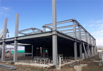
The buildings have directed their designs taking as an essential factor the loads that affect their structural system so that the construction behaves statically in an optimal way Fig.1. Then, the basic elements of design are considered making the appropriate variations in the parameters to obtain an adequate dynamic behavior [1]. That is to say, it is permanently sought that the own structure resists and does not present/display disadvantages before the dynamic loads that appear during the life of the structure specially during a telluric event.
Traditionally, to achieve this purpose, engineers have focused their work on aspects such as the mass and rigidity of the components of the structure [2]. By making these variants, the result is to minimize the mass and maximize the stiffness of the components used, so that the elements chosen for the structure come into play. With all these modifications, a better dynamism of the structures has been achieved with a greater contribution in terms of the characteristics of each of the components that make them up [3]. Damping is of vital importance in the dynamic operation of a structure, since it generates a considerable contribution in terms of the absorption characteristics of the oscillatory movement that the structure can present [4]. Thus, if the required damping is available, a reduction of the dynamic enlargement factor and therefore a higher accuracy in restricting the movement of the structure can be achieved, obtaining a high attenuation of the vibrations, thus reducing their effect on the structure and the degree of failure that this causes in each component. Vibrations as such have become very important throughout history, so the human being has seen the importance of studying certain parameters that are presented daily, in order to find an explanation, try to understand their behavior and in turn take advantage of these elements that can offer some benefit [5].
Within the design of bodies, structures, machinery and elements, vibrations become an undesirable but inevitable phenomenon, which can produce serious damage or failures to the point of total failure or collapse of the system, therefore, the aim is to try to reduce this effect as much as possible and thus avoid its consequences [6]. The main objective of this paper is to design and build a scale prototype of a viscous damping gantry, allowing to show the contribution that the shock absorber provides to the structure and to analyze the behavior that the prototype presents when exposed to dynamic loads, induced by the horizontal movement of the floor to which the gantry is embedded. A vibration is a repetitive movement that occurs around a reference position known as the equilibrium position, after suffering a disturbance or stimulus that gives rise to the movement. The characteristic of this movement is that it repeats itself after a time interval, and stops in the equilibrium position when there is no longer any disturbance, i.e. when the applied force is equal to zero [7]. Within the vibrations, some important elements are considered that allow this movement to be given. These elements are the inertia, the elasticity and depending on the type of system, the damping is considered to attenuate the excesses of displacement, these elements act among themselves to give origin to the interaction between kinetic and potential energies, which are those that characterize the movement [8]. Then, at the beginning, a vibration table will be manufactured containing the mechanism and all the elements necessary to induce the movement to the portal. For this, as a first point, it is necessary to define the necessary mechanism for the generation of the movement, which is of the horizontal repetitive type, characteristic of the vibratory movement.
Fig. 1Undershocked gantry of the structure under construction of the ESPE University headquarters
2. Design of the structure
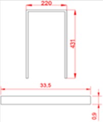
The gantry will be built as a scale prototype, show in Fig. 2, whose material is hardened steel, with an elasticity coefficient of = 200000 MPa and a Poisson coefficient of 0.29 [9]. The length of the gantry columns is 43.1 cm, the length of the beam is 22 cm and the cross-sectional area of each element is 33.5 mm×0.9 mm.
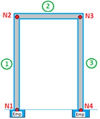
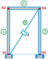
Fig. 2a) Gantry dimensions in centimeters, b) undamped gantry, c) damped gantry
a)
b)
c)
The shock absorber used in the prototype is considered to be a Taylor viscous shock absorber [10]. For this application, it must have a damping coefficient in order to adapt to the characteristics of the gantry [11]. To obtain the coefficient, the damping force equation is used, for which an external force F is first placed at the end of the damper in a vertical position. Then, to find the velocity v, the time it takes to move in a determined distance is taken [12]. Once the velocity is determined, and the weight that in the equation represents the applied force, when clearing, the damping coefficient:
The process to determine the damping coefficient is done experimentally, so some tests are done and with this we get an average of the coefficients, illustrated in Table 1.
Table 1Obtaining the damping coefficient
Exhibit | [N] | [m] | [s] | [m/s] | [N.s/m] |
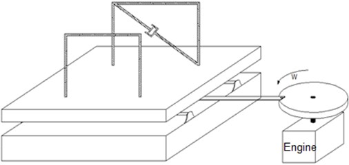
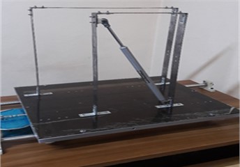
When calculating the average between the coefficients obtained in the different tests, the damping coefficient 34 N.s/m is obtained. Among the alternatives based on the type of movement to be implemented, the most feasible and appropriate for this application is the crank-slide mechanism [13]. This mechanism is one of the simplest in its composition, because in its general form it requires two bars (the crank and the connecting rod), and a sliding element called a slide, apart from an element that drives the movement as a motor, which is coupled to the crank [14]. Then, adapting this concept to the vibration table, the mechanism must slide in a repetitive way a base on which the portal will be embedded, the same one that must be attached to the slide system forming part of it. Fig. 3, is a schematic representation of the idea to be implemented, for which it is required axes that serve as guides, a disk with an eccentric that resembles a crank, a motor that generates the movement, a table with a sliding system that allows the movements of the slide and a frame.
Fig. 3Equipment diagram
3. Experimental structure assembly
In the elaboration of the mechanism for the generation of movement, firstly, the purchase of two stainless steel axes of diameter ¾ is considered, which are used as guides where the slide moves, while supporting the weight that this implies. Therefore, the diameter is considered to avoid buckling and the material is because of its good surface finish [15]. A 45×55 cm square steel tube frame is manufactured, with a thickness of 1 mm, which serves as a support for the base to which the structures are embedded. This metal frame is also fitted with the system that helps with the movement of the structure. This system is composed of two wheels placed at the sides of the axles, which allow an optimal displacement by reducing the influence of resistance that opposes the movement. These wheels are made of polymer to avoid the greatest possible wear between elements due to friction [16]. They are attached to the aluminum frame through plates previously welded by means of bolts and horns which give the necessary separation height to avoid friction with the axles. A total of 8 wheels are used, located in 4 pairs, 2 on each side of the frame. A motor is acquired to drive the movement, which is chosen giving priority to the torque characteristic, which is the essential to make the table move when coupled to the square tube frame and the structure located on it. Taking into account this criterion, we look for a small electric motor reducer that does not represent much weight for the machine in general. The selection is based on the torque , where is the force with which the mechanism is intended to be moved and is the length of the crank [17]:
As data, the maximum load that is going to move the motor and the longest crank length are considered, this is with the purpose of calculating the minimum torque necessary to generate the movement in the most critical conditions where 5 Kg and 6 cm = 0.06 m, obtaining as a result that the torque required for the gearmotor is 0.3 Kg∙m. Then to determine the torque of the electric motor to choose, the following formulas are used, where is the mechanical power, is the angular speed, obtaining directly the torque in Kg∙m [18]:
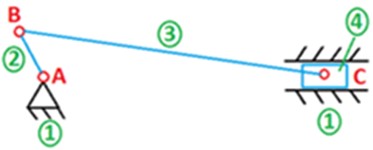
To choose the right engine, there are two criteria to consider. The first is by comparing this torque value obtained from the motor characteristics, which must be greater than the torque calculated under the most critical conditions. And the second is by applying the torque formula, in which the calculated value is divided into the engine characteristics for the lever arm, obtaining the force that the engine supports, which must be greater than the force calculated under the most critical conditions [19]. Finally, based on these criteria, the GMX-7MP008A type gearmotor was acquired, whose voltage is 20 V, current 1A and RPM 465. Two aluminium discs are attached to the motor shaft, the first one to make direct shaft clamping by means of a block that enters under pressure, and the second one that is then joined by means of some small pillars at a certain height. This disc has holes made eccentrically where the connecting bar that transmits the movement to the metal frame (slide) is attached. The disc with the eccentric holes acts as a crank, which receives the direct movement of the motor. These holes are 4 separated every 1.5 cm in order to offer variation in the amplitudes of the movement, depending on the needs, therefore, the union bar is joined to the disc by means of a bolt that gives it the necessary adjustment. Under this type of design, the system is easily detachable. For the connecting rod (connecting rod) between the slide and the crank, a small stainless steel axle is purchased, 56 cm long, with a diameter of 9.5 mm, so that it does not exert too much weight, but fulfils the required function. For this purpose, a thread is made at the ends of the bar to bolt two elements that serve to attach the bar to the disc and the frame. The coupling elements, connected by bolted connections to both the disc and the frame, are known as ball-and-socket joints, which offer the necessary degrees of rotation freedom to facilitate the movement, preventing it from getting stuck and absorbing the small turns of the bar caused by its own movement and working speed [20]. Finally, all the elements are assembled and the mechanism for generating movement is obtained, as illustrated in Fig. 4.
The frame is the support where the different elements that make up the machine are located, and on which the whole set is assembled. For the manufacture of the frame, several aspects are considered such as the material, which was chosen to be wood to give an aesthetic touch to the table and at the same time to be able to support the loads. Therefore, the support wood used has a thickness of 3 cm to avoid sagging, and in turn accommodate the elements to allow them to work optimally. As in the case of the motor, for which it has assembled in its lower part a wooden coupling system that gives it the correct support, avoiding unnecessary movements or off-centre.
Fig. 4a) Mechanism for generating movement on the vibration table, b) kinematic diagram
a)
b)
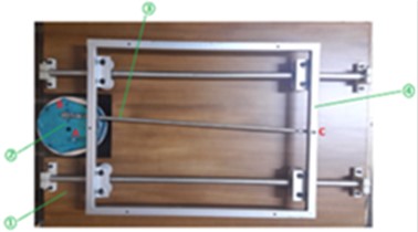
As mentioned above, the motor is of direct current electric type with a maximum voltage of 20 V, so a source providing this type of power is required. For this purpose, a power supply is acquired considering important aspects such as the one that allows transforming the current from alternating to direct, besides offering the characteristic of variability in the output voltage, to provide the option of modifying the speed at which the motor operates [21]. Under these criteria the chosen source has a source: Variable AC/DC, current at 1 A, input voltage at 110 V and output voltage at 3-20 V. The idea of reducing the weight of the whole machine and therefore the load on the engine is taken into account when manufacturing the support base for the gantries. Based on this, it is made of acrylic with the necessary adaptations to fit the steel frame and at the same time with holes that allow the embedding of the gantries to it. The elements that complement the mechanism for the generation of movement are coupled, which are the axles, the steel frame with the sliding system (wheels), and the bar that transmits the movement. Finally, the acrylic base is joined to the metal frame by means of bolted joints. The prototype of the structure analyzed is a portal made to scale, which must necessarily be made with materials and cross sections that give it the flexibility necessary to resemble the movement of a real portal because the loads to be induced come from the movement of the vibrating table, since if it is made very rigid this would not be achieved. For this purpose, among the possible materials available, a rectangular profile of tempered steel is used, with an extremely thin cross section that allows it to bend with the application of little load and then return to its original position, simulating the behaviour of the structure in the face of dynamic loads. The material of the frame is hardened steel, with a coefficient of elasticity of 2e11 Pa, Poisson's coefficient of 0.3 with a density of steel of 7850 kg/m3 [22]. The portal elements have a column length of 43.1 cm, beam length of 22 cm, and a cross-sectional area of 33.5 mm×0.9 cm. To build the gantry, that is to say, to assemble its elements, the most suitable alternative is to use bolted joints through angles, to provide the necessary support at the nodes; likewise, in the recesses, a double angle support is used, which gives the recess condition and deprives these nodes of the displacements in all the degrees of freedom. When making bolted connections, the aim is for the prototype to be easily dismantled, giving the possibility of testing different types of structure configurations within the academic application that can be given to the vibration table, illustrated in Fig. 5.
The shock absorber, whose damping coefficient has already been determined, is made of steel material, of the Taylor viscous type, whose fluid is hydraulic oil number 10, with a total length of 55 cm, rod length of 23 cm, cylinder length of 32 cm and stroke of 20 cm. To mount the shock absorber on the gantry, two couplings manufactured precisely to provide support to the structure are used, joined to the shock absorber at its ends by pins. At each end, the shock absorber has a strap where these devices can be joined. Finally, when the shock absorber is assembled, its rod must be contracted to provide sliding and damping in both directions (positive and negative) of the structure’s movement. The assembly is shown in Fig. 6.
In order to present the contribution that the shock absorber provides to the gantry, the use of basic instrumentation is implemented to obtain the graphic representation of the type of movement being analyzed, by means of an interface that allows this action to be carried out. An accelerometer sensor is used as an acquisition instrument, which allows working on the analysis of several degrees of freedom, depending on its connection; an ARDUINO is also used, as an input and output data acquisition and management card, which is previously programmed for the interaction with the sensor where the information is obtained and then sent to the software that graphs the movement through the graphic interface. The Arduino program codification for data acquisition, through the MPU-6050 module, is obtained by downloading the module’s own libraries that are included as sensor complements, then they are copied in the Arduino installation folder in the “libraries” folder, the Arduino program, the start tab is displayed, and in the examples part the code of the main program elaborated for the MPU-6050 is obtained, which is modified depending on the application and the measurement to be performed [23]. To obtain the motion graphics through the instrumentation and the connection to the computer by means of the USB cable, the Microsoft Excel graphic interface is used, through the extraction of data in real time by means of a compiler such as the “RS232 Data Logger”, that allows to generate them in a “.TXT” file, and then copy them to EXCEL where the motion graphics are obtained. Here it is important to take into account the data transmission speed of the sensor, which is 115200, the same speed selected in the data compiler. The assembly of the instrumentation in the prototype is very simple, since the sensor must only be located by means of bolted joints in the element or in the node of the structure that is required to be analyzed and we proceed to execute the procedure for the data collection.
Fig. 5Assembly of the gantries in the frame
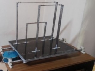
Fig. 6Cushioned gantry assembly
4. Graphical interface optimization
In order to obtain the movement graphs through the instrumentation and the connection to the computer by means of the USB cable, three possibilities are proposed to implement the graphic interface.
The first is the use of MATLAB software which, through the programming of a GUIDE, collects the data and presents them in a graph that is constructed as time goes by. To execute this interface you need the two files with the extensions “.fig” and “.m”, created when programming the GUIDE inside the same folder; proceed to open the file “Interfaz_Grafica.m” in Matlab, coming from the Arduino to the computer via USB interface. The graphical interface obtained after performing the GUIDE is shown in Fig. 7.
The problem with this implementation is that the communication between MATLAB and ARDUINO is slow, i.e. there is a time delay until the data is collected and plotted in real time.
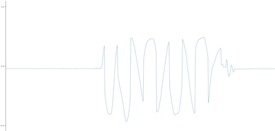
The second possibility is to obtain the motion plots through the Arduino program interface itself, through the “Serial Plotter” command, located in the tools tab. In the window that opens, it is important to select the data transmission speed of the sensor itself, which is 115200, in the tab located at the bottom left. In this interface, the graph shows the movement in real time without delays, but in a simple way, as shown in Fig. 8.
Fig. 7MATLAB graphical interface
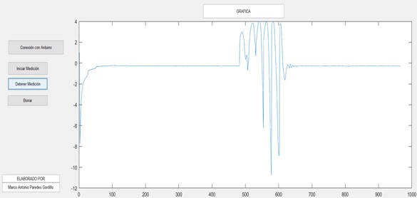
Fig. 8ARDUINO graphical interface
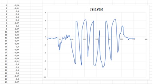
The third possibility is through the extraction of data in real time by means of a compiler such as the ”RS232 Data Logger”, which allows to generate them in a “.TXT” file, and then copy them to EXCEL where the graph of the movement is obtained. Here it is important to take into account the data transmission speed of the sensor itself, which is 115200, the same that is selected in the data compiler, as illustrated in Fig. 9.
Fig. 9EXCEL graphical interface
5. Obtaining experimental data
In this part, in order to carry out the demonstration and testing of the prototype, we proceed to analyze the movement in the horizontal direction of the gantry, using the proposed methodology and the instrumentation implemented with the accelerometer through the MPU-6050 module, which will be located at the extreme nodes (considered the most critical ones). That is to say that only data of the movement in the degree of freedom along the -axis will be taken, due to the fact that in this axis the greatest displacement of the structure occurs.
The third method is used as the graphing interface, in which first the data corresponding to each of the nodes is compiled and then exported to an EXCEL spreadsheet to obtain the graphs, which are shown below in the results section. It should be noted that, for a better analysis of the results, when graphing in Excel, the abscissa axis can be modified to include the time in which the test was performed, subdivided into intervals according to the number of points acquired. The tests are performed for the two cases of damped and undamped systems, in order to obtain a comparison of the behavior under the loads induced by the vibration table, which is appropriate depending on the conditions to be analyzed, which in this case have been chosen those illustrated in Table 2.
Table 2Test parameters
Parameter | Value |
Voltage | 3 volts |
Crank length | 3 centimeters |
Total slide displacement | 6 centimeters |
Test time | 10 seconds |
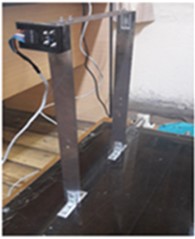
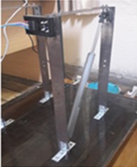
The procedure followed to perform the experimental validation corresponding to free and damped vibration is the same, being the damper the one that modifies the behavior of the system. The following is the result of the analysis carried out on the undamped portal frame, performing the specific analysis to determine the behavior at node 2, shown in Fig. 10.
Fig. 10a) Location of the module at node 2 – undamped gantry, b) graph obtained from the test
a)
b)
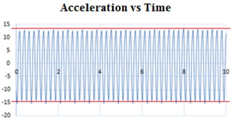
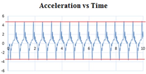
Fig. 11 shows the results of the analysis of the undamped portal frame, focusing the analysis specifically on the behavior of node 3.
Fig. 11a) Location of the module at node 3 – undamped gantry, b) graph obtained from test
a)
b)
When comparing the plots obtained for the undamped portal frame for both nodes 2 and 3, it can be determined that they are very similar, since they have the same characteristics and shape at each point analyzed, and focusing on the maximum amplitude, it is determined that it is the same for both plots of approximately 15 cm. The difference in the result obtained from the analysis between node 2 and node 3 without damping is based on the amplitude reached specifically in the lower axis. For node 2 a value of approximately 15 cm is reached, as shown in Fig. 10; on the other hand, for node 3 a value of approximately 12 cm is reached, as shown in Fig. 11. This small variation is due to the location of the nodes with respect to the movement generation point, node 2 being more distant from it.
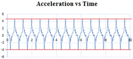
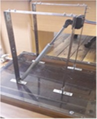
In order to analyze the behavior of the damped gantry in the system, a hydraulic cylinder described in previous sections is incorporated, the procedure being similar when the gantry was analyzed in a free way. Next, Fig. 12 shows the result of the analysis of the damped gantry, making the specific analysis to know the behavior at node 2.
Fig. 12a) Location of the module at node 2 – damped gantry, b) plot obtained from test
a)
b)
Fig. 13 shows the results of the analysis of the damped portal frame, focusing specifically on the behavior of node 3.
Analyzing the graphs obtained for the viscous damped portal frame at both nodes 2 and 3, it can be determined that they are almost identical in their characteristics, and that they have the same shape at most points, with the highest point being approximately 4 cm. The difference in the result obtained from the analysis between node 2 and node 3 with damping is based on the amplitude reached specifically in the lower axis. For node 2 a value of approximately 4 cm is reached, as shown in Fig. 12, while for node 3 a value of approximately 3.7 cm is reached, as shown in Fig. 13. This small variation is due to the location of the nodes with respect to the movement generation point, with node 2 being more distant from it.
Fig. 13a) Location of the module at node 3 – damped portal frame, b) plot obtained from the test
a)
b)
6. Analysis and results
In order to carry out the demonstration and performance tests of the prototype, the analysis of the movement in the horizontal direction of the gantry (Acceleration vs time graph) is carried out, using the proposed methodology and the instrumentation implemented with the accelerometer through the MPU -6050 module, which will be located in the extreme nodes (considered the most critical). That is to say that only data of the movement in the degree of freedom along the -axis will be taken, due to the fact that in this axis the greater displacement of the structure is presented.
In Fig. 14, the result of the simulation and analysis performed by FEM on the undamped gantry is shown, obtaining a maximum stress of 554.5 MPa and presenting a maximum deformation of 88.92 mm in its structure during the generated movement.
Fig. 14FEM results for undamped portal frame: a) Stress analysis, b) Strain analysis
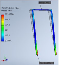
a)
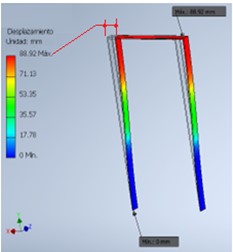
b)
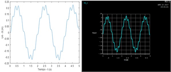
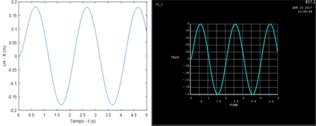
Fig. 15 shows the simulation of the graph of the behavior of the structure without damping, in which the recreation of the movement of the portal frame can be observed.
Fig. 15Gantry vibration without damping on the x-axis
In Fig 16, the result of the simulation and analysis performed by FEM on the damped gantry is shown, obtaining a maximum stress of 224.3 MPa and presenting a maximum deformation of 6.51 mm in its structure during the generated movement.
Fig. 16FEM results for damped portal frame: a) stress analysis, b) deformation analysis
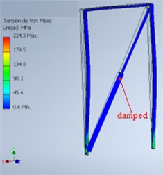
a)
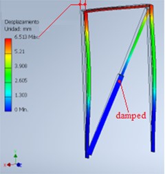
b)
Fig. 17 shows the simulation of the graph of the behavior of the structure with damping, in which the recreation of the movement of the portal frame can be observed.
Fig. 17Gantry vibration with damping on the x-axis
Analyzing the results obtained in the practical application of the prototype under the previously established conditions, it can be determined that there is a notable reduction in the amplitudes of the acceleration points taken with the MPU-6050 module in the graph corresponding to the damped system in comparison to the undamped system, evaluated in the same node. This is verified by referencing the highest points in each graph where the difference is between 7 and 9 points that is approximately equivalent to 45 %, being a positive contribution that gives the shock absorber to the gantry.
At the same time, it can be seen that, when the structure is damped, the graph decreases in terms of the number of oscillations that occur in the same time of evaluation, which means that the structure has moved a smaller number of times to a low acceleration, managing to minimize the high peaks that are observed in the graph of the undamped system.
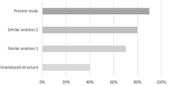
Fig. 18 shows a diagram comparing the performance of this study, which analyzes the behavior of a viscous damped gantry, with studies of similar systems. The graph shows that the present study has an acceptable performance in comparison with similar studies carried out.
Fig. 18Comparison with other studies
7. Conclusions
It can be clearly determined that the viscous damper provides a considerable contribution to the structure of the gantry, helping with the absorption and attenuation (100 % in free vibration and 25 % in forced vibration) of the excess vibrations that are generated by the nature of the dynamic type loads, which is reflected in the analysis made to the solutions of the variables immersed in the movement, which can be obtained in each node thanks to the application of the finite elements.
The configuration in which the damper is located within a structure is another fundamental part of the structural analysis, which depends on the application required in terms of the direction in which the vibration attenuation is intended to be provided. Then, based on these two parameters, the damper is selected that has the characteristics and properties that adjust to the requirements.
The development of the proposed experimental analysis yielded similar results that were supported by the analysis by the finite element method, representing a contribution and an alternative method within the vibrational analysis of structures that presents very reliable results close to reality.
References
-
C. Wang, J. Zhao, and T.-M. Chan, “Artificial intelligence (AI)-assisted simulation-driven earthquake-resistant design framework: Taking a strong back system as an example,” Engineering Structures, Vol. 297, p. 116892, Dec. 2023, https://doi.org/10.1016/j.engstruct.2023.116892
-
N. U. Mate, S. V. Bakre, and O. R. Jaiswal, “Seismic pounding response of singled-degree-of-freedom elastic and inelastic structures using passive tuned mass damper,” International Journal of Civil Engineering, Vol. 15, No. 7, pp. 991–1005, Apr. 2017, https://doi.org/10.1007/s40999-017-0178-7
-
M. Ferraioli, “Dynamic increase factor for nonlinear static analysis of RC frame buildings against progressive collapse,” International Journal of Civil Engineering, Vol. 17, No. 3, pp. 281–303, Sep. 2017, https://doi.org/10.1007/s40999-017-0253-0
-
A. Bayraktar, A. C. Altunişik, and T. Türker, “Structural condition assessment of Birecik Highway bridge using operational modal analysis,” International Journal of Civil Engineering, Vol. 14, No. 1, pp. 35–46, Apr. 2016, https://doi.org/10.1007/s40999-016-0010-9
-
S. Baddipalli, M. Kulariya, and S. K. Saha, “Influence of masonry infills on blast response of earthquake-resistant reinforced concrete buildings,” Structures, Vol. 50, pp. 908–924, Apr. 2023, https://doi.org/10.1016/j.istruc.2023.02.078
-
C.-C. Hung and W.-T. Lu, “Tall hybrid coupled structural walls: seismic behavior and design suggestions,” International Journal of Civil Engineering, Vol. 16, No. 5, pp. 567–582, Feb. 2017, https://doi.org/10.1007/s40999-017-0162-2
-
Y. Zhong, J. W. Tu, G. Que, B. Tu, and J. Y. Xu, “Analysis and control of the coupled vibration between the ship lift and ship chamber,” International Journal of Civil Engineering, Vol. 14, No. 5, pp. 307–324, Jun. 2016, https://doi.org/10.1007/s40999-016-0041-2
-
F. Aras, T. Akbaş, H. Ekşi, and S. Çeribaşı, “Progressive damage analyses of masonry buildings by dynamic analyses,” International Journal of Civil Engineering, Vol. 18, No. 8, pp. 903–917, May 2020, https://doi.org/10.1007/s40999-020-00508-5
-
G. Du, M. Babic, F. Wu, X. Zeng, and X.-M. Bie, “Experimental and numerical studies on concrete filled circular steel tubular (CFCST) members under impact loads,” International Journal of Civil Engineering, Vol. 17, No. 8, pp. 1211–1226, Nov. 2018, https://doi.org/10.1007/s40999-018-0379-8
-
M. Bahmani and S. M. Zahrai, “Application of a comprehensive seismic retrofit procedure for steel buildings using nonlinear viscous dampers,” International Journal of Civil Engineering, Vol. 17, No. 8, pp. 1261–1279, Dec. 2018, https://doi.org/10.1007/s40999-018-0384-y
-
M. Scalvenzi, S. Ravasini, E. Brunesi, and F. Parisi, “Progressive collapse fragility of substandard and earthquake-resistant precast RC buildings,” Engineering Structures, Vol. 275, p. 115242, Jan. 2023, https://doi.org/10.1016/j.engstruct.2022.115242
-
M. A. Erberik, C. Citiloglu, and G. Erkoseoglu, “Seismic performance assessment of confined masonry construction at component and structure levels,” Bulletin of Earthquake Engineering, Vol. 17, No. 2, pp. 867–889, Sep. 2018, https://doi.org/10.1007/s10518-018-0468-8
-
S. K. Nagendran and M. A. M. Ismail, “Analysis of rockfall hazards based on the effect of rock size and shape,” International Journal of Civil Engineering, Vol. 17, No. 12, pp. 1919–1929, Apr. 2019, https://doi.org/10.1007/s40999-019-00418-1
-
Y. Zhou, H. Shao, Y. Cao, and E. M. Lui, “Application of buckling-restrained braces to earthquake-resistant design of buildings: A review,” Engineering Structures, Vol. 246, p. 112991, Nov. 2021, https://doi.org/10.1016/j.engstruct.2021.112991
-
K. Zhang and Q. Sun, “Experimental Study of reinforced concrete T-Beams strengthened with a composite of prestressed steel wire ropes embedded in polyurethane cement (PSWR-PUC),” International Journal of Civil Engineering, Vol. 16, No. 9, pp. 1109–1123, Oct. 2017, https://doi.org/10.1007/s40999-017-0264-x
-
M. Mohammadi, “Seismic behavior of sliding base isolation systems, regarding restitution factor and variable friction coefficient,” International Journal of Civil Engineering, Vol. 15, No. 2, pp. 287–298, Jan. 2017, https://doi.org/10.1007/s40999-016-0095-1
-
X. Song, J. Xu, C. Shen, F. Peña-Mora, and Z. Zeng, “A decision making system for construction temporary facilities layout planning in large-scale construction projects,” International Journal of Civil Engineering, Vol. 15, No. 2, pp. 333–353, Oct. 2016, https://doi.org/10.1007/s40999-016-0107-1
-
A. Kheyroddin, E. Emami, and A. Khalili, “RC beam-column connections retrofitted by steel prop: experimental and analytical studies,” International Journal of Civil Engineering, Vol. 18, No. 5, pp. 501–518, Nov. 2019, https://doi.org/10.1007/s40999-019-00481-8
-
X. Ning, K.-C. Lam, and M. C.-K. Lam, “A decision-making system for construction site layout planning,” Automation in Construction, Vol. 20, No. 4, pp. 459–473, Jul. 2011, https://doi.org/10.1016/j.autcon.2010.11.014
-
A. Dhamaniya and S. Chandra, “Influence of operating speed on capacity of urban arterial midblock sections,” International Journal of Civil Engineering, Vol. 15, No. 7, pp. 1053–1062, Apr. 2017, https://doi.org/10.1007/s40999-017-0206-7
-
R. Karami Mohammadi and S. Najarzade, “Semi-active control of structures equipped with MR dampers based on uniform deformation theory,” International Journal of Civil Engineering, Vol. 16, No. 8, pp. 871–885, May 2017, https://doi.org/10.1007/s40999-017-0213-8
-
M. Amin Rashidifar and A. Amin Rashidifar, “Analysis of vibration of a pipeline supported on elastic soil using differential transform method,” American Journal of Mechanical Engineering, Vol. 1, No. 4, pp. 96–102, Jul. 2013, https://doi.org/10.12691/ajme-1-4-4
-
F. Peña, P. B. Lourenço, N. Mendes, and D. V. Oliveira, “Numerical models for the seismic assessment of an old masonry tower,” Engineering Structures, Vol. 32, No. 5, pp. 1466–1478, May 2010, https://doi.org/10.1016/j.engstruct.2010.01.027
About this article

The authors have not disclosed any funding.
The datasets generated during and/or analyzed during the current study are available from the corresponding author on reasonable request.
Cristian Paredes: conceptualization and supervision. Edison Arguello: investigation and formal analysis. Carlos Sánchez: methodology and software. Marco Paredes: validation and resources.
The authors declare that they have no conflict of interest.
