Abstract
The swing torque and rotational torque after the spherical bearing is installed directly affect the performance of the spherical bearing. At this stage, the friction torque detection equipment of the spherical bearing is mainly used to detect uninstalled bearings. A set of rotation and swing after the bearing is installed is designed. Torque detection system. The detection principles of rotational torque and swing torque required for flexibility detection were analyzed, the functional design requirements and main technical indicators of the detection system were clarified, and the overall design plan of the detection system was established; the host structure of the detection system was designed, including rotational torque detection system, swing torque detection system, clamping system and calibration system; completed the scheme design of the detection control system, selected the torque sensor and servo motor, designed the main electrical control circuit of the detector; conducted error analysis of the detector.
1. Introduction
According to the requirements of aviation equipment manufacturing standards, during the manufacturing process of installing various types of aircraft operating system parts such as outer ring grooved self-lubricating bearings and spherical bearings, the swing and rotation flexibility of the inner ring of the bearing within the spherical surface of the outer ring must be inspected after the bearing is installed, check the friction torque during swing and rotation. Regarding the inspection of bearing friction torque, research in this area by foreign bearing companies started early and developed rapidly. The United States and Japan are in a leading position in the field of bearing friction torque research and have developed a large number of measuring equipment. Among them, representative products are BRG-3000 bearing torque detection system developed by VIBRAC Company of the United States [1]. This bearing torque detection system consists of a control system and a test bench. During measurement, the motor drives the inner ring of the bearing to rotate, and the torque sensor measures the starting torque value and outputs it. The advantage of this torque detection system is that it can detect the starting torque and dynamic friction of the bearing. moment. The TNJ digital torque meter developed by Japan’s SHIMPO Company is mainly used to measure the opening and closing torque of various caps, bolts and valves. The torque measurement range is (0-10) N·m. The fixture of the meter holds the outer ring of the bearing, and the measurement can be completed by manually turning the inner ring. However, manual measurement may introduce human measurement errors. In terms of bearing friction torque in China, since the 1990s, the Luoyang Bearing Research Institute has successively developed bearing friction torque measuring instruments such as M9908, M9912A, and M992 [2]. At the end of the 20th century, the Shanghai Bearing Technology Research Institute developed a The Taiwan spherical bearing friction torque testing machine is suitable for testing the friction torque of spherical bearings with large diameters and heavy loads [3]. At the same time, the possible measurement errors produced by the testing machine are analyzed. Shanghai University has developed an oscillating resistance torque tester for spherical bearings [4]. The oscillating resistance torque tester is specially used to measure the oscillating starting torque and dynamic friction torque of spherical bearings. It adopts a driving method of motor + torque sensor + elastic fork. Wu et al. [5] analyzed the development of theoretical models for friction torque of rolling bearings and summarized corresponding methods for measuring friction torque. Kumar et al. [6] elaborated on different misalignment diagnosis techniques and introduced the impact of misalignment on bearings and rotor bearing systems. König et al. [7] applied acoustic emission (AE) technology to the test bench of sliding bearings. Yu et al. [8] designed a torque measurement system for a new type of vertical measuring instrument.
At present, the rotational torque detection of spherical bearings is mainly for uninstalled bearings. The performance of the bearings installed in the parts will inevitably change, and there is no solution at home or abroad for the detection of torque in the swing direction. By designing and producing a detection system for the rotation and swing torque of the bearing after installation, the reliability of the bearing installation quality is improved. The researchers have rich experience in device development [9-10], the system has detection accuracy self check and accuracy calibration functions. After clamping the parts, it can automatically complete the flexibility check of rotation and swing, with a high level of automation. This system is highly advanced in the industry and can be promoted in the industry.
2. Inspection requirements after bearing installation
According to the requirements of aviation equipment manufacturing standards, after installation, the slotted self-lubricating bearings and spherical plain bearings in the outer ring need to be inspected for flexibility according to the method specified. When checking the swing flexibility, the inner ring of the bearing should rotate to a certain position under the action of torque Mkp. At an angle, when checking the rotational flexibility, the inner ring of the bearing should rotate a certain number of revolutions under the action of M'kp torque.
3. R and D requirements for detection systems
The bearing flexibility detection system can simulate the relative rotation and relative swing motion process of the bearing inner ring and the bearing outer ring after the spherical bearing is installed into the component, and collect real-time torque data. To achieve this requirement, the key technical indicators of the detection system are formulated as follows.
Table 1Key technical indicators of the detection system
Serial number | Key technical indicators | Indicator requirements |
1 | Rotating torque measurement range | (0.1-1.1) Nm |
2 | winging moment measuring range | (0.2-1.3) Nm |
4. The scheme of the detection system
4.1. Overall structure of detection system
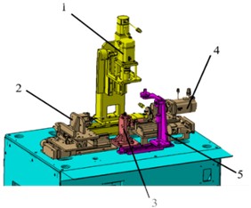
The three-dimensional model of the bearing flexibility detection system structure is shown in Fig. 1. The clamping system is responsible for clamping parts, the swing torque detection system and the rotation torque detection system are responsible for stress torque detection respectively, and the torque calibration system is responsible for verifying the accuracy of the system.
The detection system adopts an integral layout. The inner ring rotation drive system adopts a horizontal structure and is laid flat on the equipment platform table. The inner ring swing drive system adopts a vertical structure and is installed on the equipment platform table. The clamping system is installed on the equipment platform table. superior. The overall structure of the detection system is simple and compact, and it occupies a small area. The rack provides stable support and arrangement space for the components of each system. There is enough space on the main table for installing and replacing parts.
Fig. 1Overall structure of bearing flexibility detection system: 1 – swinging torque detection system; 2 – rotating torque detection system; 3 – clamping system; 4 – rotating torque detection system; 5 –torque calibration system
4.2. Detection system subsystems
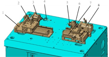
(1) Rotating torque detection system. The layout of the rotational torque detection system is shown in the Fig. 2, including the slide rail, support plate, three-claw chuck, expansion rod, turntable, torque sensor, servo drive slide rail, and servo motor, three-claw chuck, expansion rod, turntable, torque sensor The coaxial axis of the sensor and the inner ring of the bearing are in the same straight line. The main function of the rotational torque detection system is to drive the inner ring of the spherical bearing to achieve 360° rotation and detect the torque of the inner ring of the bearing when it rotates in the outer ring. The system provides torque from a servo motor, drives a torque sensor, and the inner ring of the bearing rotates. The torque sensor detects the torque in real time.
Fig. 2Rotating torque detection system: 1 – slide rail; 2 – support board; 3 – three jaw chuck; 4 – up bar; 5 – turntable; 6 – torque sensor; 7 – servo driven slide; 8 – servo motor
(2) Swing torque detection system. The swing torque detection system consists of servo motor, motor fixed plate, fixed column, torque sensor, fixed base plate, sensor fixed plate, shift fork, system fixed base plate, L-shaped fixed plate, servo drive slide rail, U-shaped bracket, fixed base plate, servo The drive slide rail and other components are shown in Fig. 3.
After the parts are clamped, the swing torque detection system provides torque by the servo motor, driving the torque sensor and the shift fork. The shift fork is inserted into the inner ring of the bearing and causes the inner ring of the bearing to swing in the outer ring. The torque sensor detects the torque in real time. Torque measurement formula were normalized according to Eq. (1):
Among them, is the torque, is the vector force, is the radius of torque application.
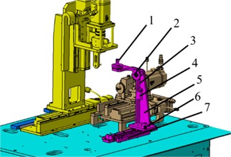
(3) Calibration system. The calibration system includes a turntable with a protruding rod, a turntable, a tension line, a weight, a calibration bracket, a positioning pin and a slide rail, as shown in Fig. 4. Rotating torque detection system self-test: a tension line is fixed on the ring groove of the turntable, and is connected through the ring groove of the turntable and the weight. The measured data of the torque sensor is compared with the torque converted by the weight. The result approximately indicates that the system is normal.
Fig. 3Swinging torque detection system: 1 – servo motor; 2 – motor fixing plate; 3 – fixed column; 4 – torque sensor; 5 – fixed base plate; 6 – sensor fixing plate; 7 – shift forks; 8 – system fixed base plate; 9 – L-shaped fixed plate; 10 – servo driven slide; 11 – U-shaped bracket; 12 – fixed base plate; 13 – servo driven slide
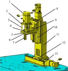
Fig. 4Calibration system: 1 – turntable with cam; 2 – turntable; 3 – tension line; 4 – weight; 5 – calibration bracket; 6 – position lock; 7 – slide rail
4.3. Torque sensor selection
The torque detection system is one of the core systems of the detector and is the data collection center of the detection system. During the torque detection process, the detection period of the inner and outer rings of the spherical bearing from a static state to a relative rotation state is very short. Using sensors to monitor the operating conditions of the spherical bearing online to accurately determine the starting torque value and swing angle will greatly Make up for the impact of human operation deficiencies on detection accuracy.
According to the design requirements, NS-NJ7-2Nm dynamic torque sensor was selected. It has the characteristics of high detection accuracy, good stability and strong anti-interference. It can measure static torque and dynamic torque, and can continuously measure forward and reverse torque without repeated zero adjustment, is a commonly used measuring device for online measurement of torque values. Its technical parameters are shown in Table 2.
Table 2NS-NJ7-2Nm dynamic torque sensor technical parameters
Indicator name | Measuring range | Accuracy level | Repeatability accuracy |
Index performance | 0-2 N·m | ±0.2 % F·S | ±0.02 % F·S |
4.4. Error analysis of detection system
As a testing equipment, the joint bearing swing and rotation torque detector inevitably has errors. Combined with the overall design plan of the detector in this article, the possible sources of errors in the detector are analyzed, mainly including the following:
(1) Torque transmission error. Use the servo motor, torque sensor and bearing inner ring drive plate to be directly connected to fix the torque sensor and servo motor to ensure that the servo motor, torque sensor and bearing inner ring drive plate are on the same axis. Bearing support and fixation are not suitable to avoid Torque measurement error caused by bearing sliding friction.
(2) Accuracy error of torque sensor. The accuracy error of the torque sensor is determined by the performance of the torque sensor. For this purpose, a torque sensor with high detection accuracy and good stability can be selected. The accuracy level of the torque sensor selected for this project is ±0.2 % F·S, and the repeatability accuracy is ±0.02 %. F·S.
(3) Static calibration of measurement systems. Determine the relationship between the input and output of the detection to determine the static characteristic indicators of the measurement system. Using the lever method for calibration, apply calibration torque to the torque sensor by multiplying the force by the force arm using the formula. In actual calibration experiments, the room temperature is maintained at 15 ℃-25 ℃, and the standard torque applied for calibration is divided into 10 levels. Apply torque by applying standard weights. To ensure the safety of the equipment, gradually load it to 80 % of the range, and then unload it gradually to no load. The loading and unloading cycles should be repeated three times, and the loading and unloading process should be slow and stable. Unloading should not occur during the loading process, and loading should not occur during the unloading process. The torque application process shows a monotonic increasing or decreasing trend. The calibration experimental data is shown in Table 3.
Table 3The calibration experimental data
Standard torque | The digital quantity of torque 𝐷 | Average value of digital quantity | ||||||
First time | Second time | Third time | ||||||
Nm | % | Loading | Uninstall | Loading | Uninstall | Loading | Uninstall | |
0 | 0 | 0 | 0 | 0 | 0 | 0 | 0 | 0 |
0.1 | 5 % | 0.085 | 0.089 | 0.084 | 0.088 | 0.090 | 0.091 | 0.088 |
…… | ||||||||
1.6 | 80 % | 1.47 | 1.53 | 1.48 | 1.55 | 1.51 | 1.58 | 1.52 |
Based on the least squares method for data curve fitting, after obtaining calibration data in calibration experiments, it is usually necessary to fit the curve between the input and output of the sensor, in order to establish a certain mapping relationship. Ideally, the input and output are expected to have a linear relationship, but in reality, the input-output characteristics of torque sensors are always nonlinear.
Assuming the input of the sensor is: , , ......
Output as: , , ......
is mainly determined by the required curve fitting accuracy. When 3, there are:
And substitute the standard torque 𝑇 and the average numerical value in Table 2, the final solution is , , , so the relationship between torque and its numerical value can be obtained: 𝑖.
5. Results and discussion
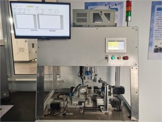
The developed bearing flexibility detection system after installation can realize the rotational torque detection and swing flexibility inspection after the bearing is installed into the parts, and has the ability to self-check the equipment accuracy. After the assembly and debugging is completed, the actual picture is shown in Fig. 5.
6. Conclusions
Designed and produced a bearing flexibility detection system, which mainly completed the following contents:
1) Analyze the rotation torque and swing torque detection principles required for flexibility detection, clarify the functional design requirements and main technical indicators of the detection system, and establish the overall design plan of the detection system.
2) Completed the design of the main engine of the detector, including the rotation torque detection system, swing torque detection system, clamping system, and calibration system.
3) Selected the torque sensor.
4) Error analysis was conducted on the detector.
Fig. 5Physical picture of bearing flexibility detection system
References
-
X. C. Zeng, “Research and implementation of friction torque measurement method of rolling bearings,” Master’s Thesis, Huazhong University of Science and Technology, 2015.
-
K. M. Zhu, “Development of friction torque measuring instrument for diagonal angular contact ball bearings,” (in Chinese), Master’s Thesis, Hefei University of Technology, 2004.
-
F. Y. Hong, Z. X. Jiang, B. Z. Di, etc, “Wear life testing machine for large and medium-sized spherical bearings,” (in Chinese), Bearings, Vol. 12, pp. 31–34, 1997, https://doi.org/10.1007/s40544-018-0206-x.pdf
-
Z. B. Cong, B. F. Li, and R. Y. Li, “Measurement method of swing friction torque of self-lubricating spherical bearings,” Measurement and Testing Technology, Vol. 43, No. 9, pp. 43–46, 2016.
-
P. L. Wu et al., “Theoretical calculation models and measurement of friction torque for rolling bearings: state of the art,” Journal of the Brazilian Society of Mechanical Sciences and Engineering, Vol. 44, No. 9, pp. 1–24, Aug. 2022, https://doi.org/10.1007/s40430-022-03726-1
-
R. Kumar et al., “A state-of-the-art review on the misalignment, failure modes and its detection methods for bearings,” MAPAN, Vol. 38, No. 1, pp. 265–274, Nov. 2022, https://doi.org/10.1007/s12647-022-00605-x
-
F. König, C. Sous, A. Ouald Chaib, and G. Jacobs, “Machine learning based anomaly detection and classification of acoustic emission events for wear monitoring in sliding bearing systems,” Tribology International, Vol. 155, p. 106811, Mar. 2021, https://doi.org/10.1016/j.triboint.2020.106811
-
Z. Yu and Y. Zhang, “Torque measurement of high-precision reducer for industrial robot,” Journal of Sensors, Vol. 2021, pp. 1–10, Jul. 2021, https://doi.org/10.1155/2021/6691481
-
Z. L. Wang et al., “A study on the installation of six point compression fixed bearings,” Group Technology and Modernization of Production, Vol. 40, No. 3, pp. 23–27, 2023.
-
Z. L. Wang, Q. G. Meng, and H. W. Qiu, “Research on improvement of clamping structure of GS250L CNC lathe,” Group Technology and Modernization of Production, Vol. 37, No. 2, pp. 40–44, 2020.
About this article

The authors have not disclosed any funding.
The datasets generated during and/or analyzed during the current study are available from the corresponding author on reasonable request.
The authors declare that they have no conflict of interest.
