Abstract
Vision-assisted surface defect detection technology is shallowly applied in crack identification of assembly building components, for this reason, the study proposes a crack identification and defect detection method for assembly building components oriented to intelligent construction. An image preprocessing algorithm is designed by improving bilateral filtering, on the basis of which an image classification model is constructed using the GhostNet algorithm, and the cracks are localized and measured using the 2D pixel positioning technique. Algorithm validation showed that the processed image denoising is better, and the peak signal-to-noise ratio of the image of the proposed algorithm is improved by 15.701 % and 2.395 %, respectively, compared to other algorithms. The F1 value of the proposed model after 50 training rounds increased by 20.970 % on average compared to other models, and the detection accuracy was as high as 0.990. The actual measurements of cracks in concrete wall panels revealed that the research-proposed method has better results compared to the traditional manual measurements, and is not subject to the limitations and interferences of factors such as manual experience, and it is more effective in the recognition of crack images. Overall, the detection method proposed by the study has high accuracy and small error, can meet the needs and standards of crack detection in assembly building components, and can intelligently locate the maximum length and width coordinates of the cracks, which is of high value in the application of crack detection in assembly building components.
1. Introduction
As a result of the construction industry’s modernization and transformation brought about by advancements in industrial technology, the Assembled Buildings (AB) sector has improved. Unlike the inefficiency of traditional construction methods, AB transfers the on-site operational work to factories and transports the components and fittings required for the building to the construction site for assembly and installation after processing and fabricating them [1-3]. Quality control is an important part of AB, and it is the cornerstone of building application value. However, current ABs frequently exhibit surface cracks, and traditional manual defect detection (D-D) is subject to human subjectivity and is difficult to achieve detection efficiency [4-5]. The advancement of computer vision technology offers a fresh approach to this issue. Scholars at home and abroad have applied D-D methods based on vision technology to various industrial fields, which have greatly improved the efficiency and accuracy of industrial D-D [6-7]. However, most of the current research focuses on small and medium-sized products, and there are fewer D-D methods for large industrial products such as AB components, and they cannot be directly applied in Crack Recognition (CR) and D-D of AB components, which have lower accuracy in recognizing component cracks. Therefore, the study proposes an intelligent construction-oriented Assembled Building Construction Cracking (ABCC) recognition and D-D method. By designing an image preprocessing algorithm to preprocess the crack image, and constructing an Image Classification (IC) model to extract and measure the cracks by using traditional digital image processing techniques, on the basis of which the dimensional measurement of cracks is realized by using 2D pixel calibration technique. The overall structure of the study consists of four parts: in the first part, the research results and shortcomings of domestic and international research on ABCC recognition and detection are summarized. In the second part, the ABCC recognition and D-D method combined with intelligent construction-oriented is studied and designed. In the third part, the proposed CR and D-D methods are experimented and analyzed. In the fourth part, the experimental results are summarized and future research directions are indicated.
2. Related works
Scholars domestically and internationally have conducted several studies on the vision-assisted D-D approach due to its widespread application in a variety of industries due to the ongoing advancements in automation technology. Jing et al. proposed a Convolutional Neural Network (CNN) incorporating depth-separable convolution to realize end-to-end defect segmentation in order to improve the actual fabric production efficiency and product quality in factories, thus improving the segmentation accuracy and detection speed [8]. For digital agriculture, increasing the product yield has emerged as a contemporary challenge. In order to detect cherries with varying degrees of ripeness in the same area and increase yield, Gai et al. proposed an enhanced YOLO-V4 deep learning model by adding a network to the YOLO-V4 backbone network, CSPDarknet53 network, and incorporating the DenseNet interlayer density [9]. Bergmann et al. designed an MVTec dataset for anomalous structures in natural image data and comprehensively evaluated it using an unsupervised anomaly detection method on the basis of a deep architecture, thus realizing pixel-accurate ground-truth annotations for all anomalies [10]. Chun proposed an automatic crack detection method incorporating image processing on the basis of optical gradient lifter, thus realizing photo detection of concrete structures under unfavorable conditions such as shadows and dirt with 99.7 % accuracy [11].
Crack defects on the surface, as the most common defect problem in the industrial field, are difficult to meet the high requirements of efficiency and accuracy by traditional detection means, for which scholars at home and abroad have explored them in various aspects. Ni et al. proposed an attentional neural network for D-D of rail surface by centroid estimation consistency guided jointly by intersections for the problem of D-D of rail surface subject to complex background interference and severe data imbalance, thus obtaining higher regression accuracy than the existing inspection techniques [12]. Ngaongam et al. employed piezoelectric discs for crack location amplitude detection based on thermoelastic damping analysis in order to optimize the vibration frequency that produces the maximum temperature difference between the crack location and the non-defect location. They discovered that high amplitude did not increase the temperature difference between the crack and non-defect location after optimization [13]. Due to the difficulty of illumination, the visual inspection techniques for defects in industry cannot fully reflect the defects on smooth surfaces, for this reason Tao et al. proposed a D-D for laptop panels, which utilizes phase-shifted reflective fringes to obtain parcel phase maps for detection, and an improved network on the basis of deep learning for recognition [14]. Qiu et al. proposed an effective framework consisting of an image registration module and a D-D module for the high reflectivity and various defect patterns on metal surfaces, and constructed the D-D module using an image differencing algorithm with a priori constraints based on the algorithm of double weighted principal component analysis [15]. Aiming at the traditional visual crack detection method which is highly subjective and influenced by the staff, E. Mohammed Abdelkader proposed a new adaptive-based method. Global context and local feature extraction is performed by an improved visual geometric group network and structural optimization is performed using K-nearest neighbor and differential evolution. The method achieved good results in terms of overall accuracy as well as Kappa coefficient and Yoden index [16]. X. Chen et al. In order to solve the problem that the measurement accuracy of 3D laser scanner has limitations for 3D crack detection methods based on point cloud, an automatic crack detection method fusing 3D point cloud and 2D images was proposed. Coarse extraction of crack images was performed by the improved Otsu method and finely proposed using connected domain labeling and morphological methods, which resulted in an experimental result of AP89.0 % [17].
When the aforementioned information is combined, it becomes clear that as automation continues to advance, vision-assisted inspection technology has been thoroughly researched across a number of industries, particularly in the area of industrial D-D. However, with the continuous development of intelligent construction, there are fewer ABCC recognition and D-D studies oriented to this field, and the existing research methods cannot be directly applied in AB scenarios. In addition, D-D for AB requires higher accuracy than traditional buildings, and the D-D application environment and so on are even more affecting the development prospect of intelligent buildings. Therefore, the study proposes an ABCC recognition with D-D method. An image preprocessing algorithm is designed based on improved Bilateral Filtering (BF), and the GhostNet algorithm is used to construct an IC model to extract and measure the cracks. Meanwhile, the study innovatively designed an AB-oriented 2D pixel calibration technique to locate and size the cracks, with a view to promoting the value of vision-assisted D-D in smart construction.
3. Assembled building construction cracking identification and defect detection method design
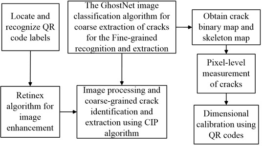
A CR and detection method is proposed for component surface cracks in AB. A Crack Image Pre-processing (CIP) algorithm is designed and the IC model is constructed using traditional digital image processing techniques. Finally, a 2D pixel calibration technique is introduced to realize ABCC recognition with D-D.
3.1. CIP algorithm based on improved bilateral filtering
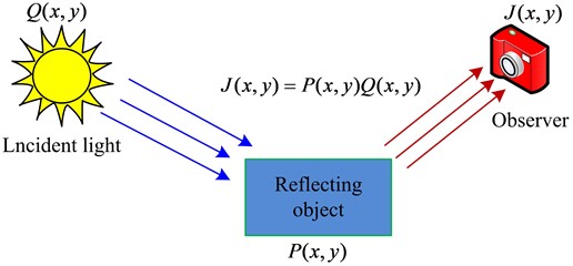
Before crack identification, preprocessing the image is frequently required to guarantee image quality. Therefore, the study proposes a BF-based CIP algorithm. Firstly, the Retinex algorithm is used for image enhancement, the improved BF is used for image denoising, and finally the Histogram Equalization (HE) and Laplace correction are combined for image detail enhancement [18-20]. Among them, Retinex algorithm, as an image enhancement algorithm with a color recovery factor, it can well achieve image color enhancement, image defogging, and color image recovery [21-22]. Its main principle is shown in Fig. 1.
Fig. 1Retinex schematic
Eq. (1) displays the Retinex algorithm’s mathematical expression:
where, J(x,y) denotes the observer or observation main viewpoint, P denotes the reflected object. Q denotes the incident light, and x and y denote the coordinate values. In order to obtain the enhanced image, the incident image is replaced and then calculated using Gaussian filtering. And the specific mathematical expression formula is shown in Eq. (2):
where, D(x,y) denotes the Gaussian filtered processed image and F(x,y) denotes the Gaussian function. k denotes the normalization parameter of the Gaussian function and δ denotes the scale parameter of the Gaussian function. However, the Gaussian function will make the image blurrier and at the same time compress the dynamic range of the image. Therefore, the study utilizes Gaussian filtering with different parameters to process the image separately and then generates the output image by weighted summation. In practical detection, the output image often has various background noises, and further denoising of the image is required. However, the traditional BF apparatus does not meet the requirement of AB to construct crack-preserving edges. Therefore, the study innovatively utilizes the segmentation function to improve the gray scale kernel function of BF. According to the constructed threshold and normalized Gray Value (GV), the improved gray kernel function is shown in Eq. (3):
where, A denotes the threshold value, Δ denotes the absolute value of the difference between the GV of the center pixel point and the GV of the neighboring pixel points normalized. ∂ denotes the standard deviation of the image, N denotes the number of gray levels of the image, and Hα is the grayscale kernel function. gα and gβ denote the GV of the image pixel points α and β, respectively, and ωh denotes the gray level difference. Improving the grayscale kernel function does not completely guarantee that the strong noise in the background of the image is completely removed, so the study uses the difference between the strong noise and the pixel values of the nearby points as the basis for the establishment of the regional similarity model. Eq. (4) displays the precise calculation formula:
where, α1(x,y) denotes the pixel value of any pixel point in the image and |S| denotes the number of all pixel points in the region. ωd denotes the gray level difference within the region, α2(i,j) is the pixel value of any pixel point in the neighborhood, and i and j denote the pixel coordinates. In the meantime, the model is further deduced, and Eq. (5) illustrates the primary procedure:
The study uses median filtering to remove the strong noise obtained from modeling calculations. Median filtering is able to pick out the strong noise in the image before processing, while still retaining the image details with high GV. Eq. (6) displays the formula for its specific expression:
where, (x,y) is the strong noise point and B(x,y) is the pixel value of all pixel points centered on (x,y) within the median filter. Since the contrast of the crack image is reduced after Retinex and improved BF processing, and the smooth image is not conducive to perform CR with D-D with high accuracy requirements, the study utilizes the HE technique with Laplace correction to sharpen the output image. Using a set of rules, the HE approach redistributes the image’s pixel values based on the original image histogram. And the transformation is mainly carried out with the cumulative distribution function [23-24]. The specific expression formula is shown in Eq. (7):
where, Rk denotes the gray level after transformation, A(rk) denotes the transformation function, and rk denotes the gray level before transformation. n denotes the total pixels in the image and αr(ri) denotes the GV of a level of the original image. The Laplace correction judges the gray level change of the pixel point to be calculated based on the gradient value of the gray level of the pixel point calculated with its 8 neighbors, and it has some stability in image rotation. The expression formula of the Laplace correction in the domain is shown in Eq. (8):
where, ∇2g denotes the Laplace value. According to the Laplace calculated value, the final image sharpening value can be further obtained as shown in Eq. (9):
where, l(x,y) denotes the sharpening result value. Combining the aforementioned, Fig. 2 depicts the flow of the CIF algorithm suggested in the study.
Fig. 2CIF algorithm flowchart
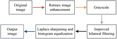
The effectiveness of industrial camera equipment to capture cracks in AB members is limited by a number of factors, and image enhancement is performed by Retinex to filter out the effect of light on the pictures. On this basis, image denoising is performed using improved BF and image contrast is improved using a hybrid image detail enhancement method of HE and Laplacian. The CIF is a combination of several algorithms, which maximizes the retention of the edges of the cracks in the building components while feature extraction and preprocessing of the graphic, facilitating the subsequent recognition and D-D.
3.2. Detection method combining CIP algorithm and image classification modeling
To effectively improve the recognition of ABCC and the accuracy of D-D, the study utilizes the traditional digital image processing techniques to construct the IC model, and combines the CIP algorithm as well as the two-dimensional code pixel size calibration method to perform CR and D-D. Since the traditional image segmentation algorithms are not able to achieve effective segmentation of the coarsely extracted cracks, and undifferentiated local thresholding will reduce the segmentation efficiency. Therefore, the study utilizes the IC algorithm based on overlapping sliding windows to construct the IC model, as shown in Fig. 3.
Fig. 3Image classification modeling process
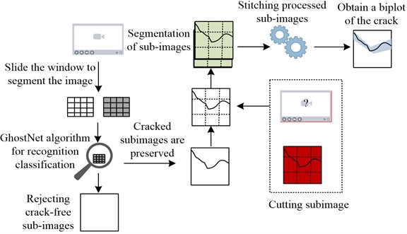
Considering that high resolution images generate many sub-image blocks after sliding window image cropping, common CNN algorithms cannot meet the requirement of efficient detection, so the lightweight network GhostNet is utilized as the algorithm for CR. GhostNet can obtain feature images with more semantics at a smaller cost, and its convolution formula is shown in Eq. (10):
where, C0 denotes the initial convolution, M denotes the convolution kernels in the first part, and Z denotes the convolution multiplier. Combining the above, the IC model for CR with measurement is shown in Fig. 4.
Fig. 4Crack identification and measurement process
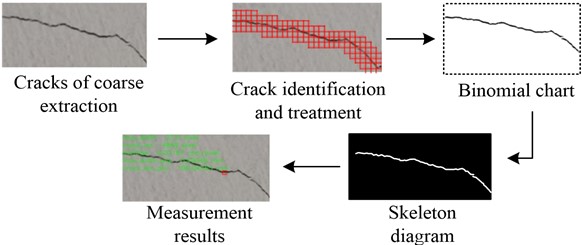
The crack image coarsely extracted using the CIP algorithm is shown in Fig. 4(a), and the recognition result obtained by GhostNet on the cropped sub-image blocks is shown in Fig. 4(b). Fig. 4(c) displays the biplot that was produced by segmenting the cracks using Otsu threshold segmentation based on this recognition result. The skeleton of the fracture that was discovered by further honing the binary map is displayed in Fig. 4(d). Finally, the pixel dimensions of the cracks are calculated and converted to the actual physical dimensions to obtain the measured result map as shown in Fig. 4(e), and the place where the maximum width of the crack is located is marked. Therefore, the flow of the CR and D-D method designed based on the CIP algorithm and IC model is shown in Fig. 5.
Fig. 5Crack identification and defect detection method flow
The study utilizes Quick Response Code (QR Code) to calibrate the pixel dimensions and transforms the pixel dimensions into physical dimensions based on the results of the calibration. QR Code can hold more information than traditional barcodes and has high reliability [25-26]. The study utilizes QR Code technology for crack size calibration, encoding, recognition and localization of QR code through Python open source library and erasing the QR code after completing the localization using hydrodynamics based image patching algorithm. According to QR Code imaging, when the image plane is parallel to the reference plane, the conversion formula of pixel size to physical size is shown in Eq. (11):
where, χ denotes the actual physical size of the target in mm, ℏ denotes the conversion ratio, and γ denotes the pixel size of the target in pixel. At the same time, considering the practical industrial application environment, the study utilizes the target method for pixel size calibration, and uses the customized QR Code label as the reference. And the edge length of each side is calculated based on the four corner coordinates of the QR Code, and the average value of the edge length is utilized to reduce the bias generated by the shooting tilt. As a result, the imaging method of QR Code is shown in Fig. 6.
Fig. 6Schematic diagram of QR code imaging
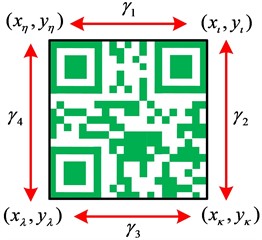
a) Theoretical parallel
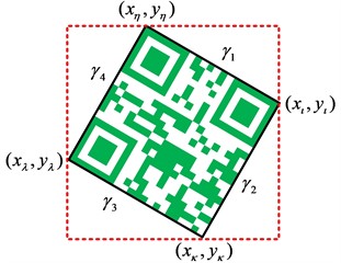
b) Physical inclination
According to the schematic diagram of the four corners and four edges of the QR Code in Fig. 6(a) and the calculated coordinates of the four corners, the imaging dimensions of the four edges of the QR Code are further calculated by using the Euclidean distance formula, and the mathematical formula is shown in Eq. (12):
where, η, ι, κ and λ denote the four sides of QR Code, respectively. To minimize the deviation in imaging size caused by the offset of the shooting viewpoint, this study calculates the pixel size by taking the average value of the four sides of the QR Code, as shown in Eq. (13):
In addition, the study used Peak Signal to Noise Ratio (PSNR) and Structural Similarity (SSIM) as the image quality evaluation formulas for evaluating the CIP algorithm [27-29]. Eq. (14) displays the formula for calculating PSNR:
where, O(i,j) is the original grayscale image and o(i,j) is the image processed by the algorithm after adding noise. H denotes the height of the image and W denotes the width of the image. The SSIM calculation formula is shown in Eq. (15):
where, uO denotes the mean value of the original grayscale image and uo denotes the mean value of the processed image. v2O and v2o denote the respective variances, vOo denotes the covariance of the two images, and C1 denotes the gray level function of the image.
4. Assembled building construction cracking identification and D-D method validation
The PSNR and SSIM values of the proposed CIP algorithm are first validated in order to confirm the efficacy of the suggested ABCC identification with D-D approach of the study. Secondly, the proposed IC model was further validated in terms of accuracy, precision, and recall. Finally, crack measurement experiments were conducted using the proposed detection method.
4.1. CIP algorithm validation
The entire validation process of the crack identification and defect detection method for assembled building components is shown in Fig. 7. The study compared the performance of various filtering algorithms using Matlab R2015a software in order to guarantee the dependability of the CIP method. Among them, the specific comparison results for Crack 1 are shown in Fig. 8.
Fig. 7Experimental validation process
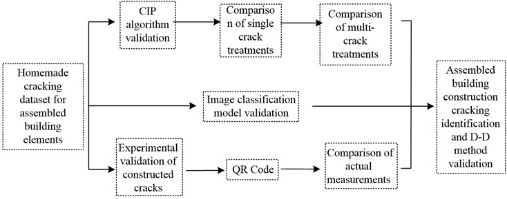
Fig. 8(a) displays the original ABCC image, while Fig. 7(b) illustrates the impact of cracks with the inclusion of noise. When Fig. 8(c) and 8(d) are compared, it is evident that the image has a lot of noise and that the denoising effect achieved following preprocessing using the conventional BF method is not sufficient. Additionally, the end borders of the cracks are not well preserved. In order to further confirm the superiority of the CIP algorithm, the study further compares the processing results of different filtering algorithms in multi-crack images. This is specifically shown in Fig. 9.
As can be seen from the comparison in Fig. 9, the CIP algorithm is superior in image processing of multiple cracks. Overall, the CIP algorithm proposed by the study eliminates a lot of noise from the processed image compared with the traditional method, and presents GV close to the original image, and is superior in crack edge processing. Meanwhile, the study introduced wavelet transform and Block Matching 3D (BM3D) to compare the processing effect. Additionally, Table 1 displays the comparison results.
Fig. 8Comparison of crack image preprocessing effects
a) Original picture of the crack
b) Crack plus noise picture
c) Bilateral filtering
d) CIP
Fig. 9Comparison of the effect of multi-crack image processing
a) Original picture of the crack
b) Crack plus noise picture
c) Bilateral filtering
d) CIP
Table 1Comparison of the evaluation results of the four methods
Method | PSNR (dB) | SSIM |
Bilateral filtering | 14.36 | 0.25 |
CIP | 30.36 | 0.80 |
Wavelet transform | 26.24 | 0.46 |
BM3D | 29.65 | 0.71 |
In Table 1, the processed image is better if the measurement indicator’s PSNR value is higher, and the noise reduction impact is greater if the SSIM value is closer to 1. Comparing the four methods, it can be seen that CIP has the highest PSNR and SSIM values, which indicates that the effectiveness of the CIP algorithm is better. The PSNR value of CIP is improved by 111.421 % compared to conventional BF. The SSIM value of CIP is increased by 73.913 % and 12.676 % compared to wavelet transform and BM3D algorithms respectively. This indicates that the CIP algorithm is able to maintain the image clarity of AB constructed cracks as well as retain the edge details of the cracks, while effectively removing the interference of background noise and improving the image processing effect, which is conducive to the improvement of the subsequent recognition and detection accuracy of the image cracks.
4.2. Image classification model validation
An Assembled Building Construction Cracking Dataset (ABCCD) for IC model training and evaluation was created utilizing the CIP and overlapping sliding window algorithms in order to verify the performance of the suggested IC model. Firstly, the smart phone is used to collect the crack images, and the collected crack images are preprocessed, and the images are classified with the labels of “crack” and “background”, and finally 20,000 crack images and background images are obtained respectively. Finally, 20000 crack images and background images are obtained respectively, and the dataset is divided into test set, validation set and training set according to the ratio of 1:1:8 for experiments. Fig. 10 displays the variations in the loss values after 50 iterations of experimental training.
Fig. 10Loss values and performance variation of image classification models
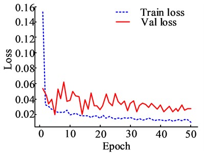
a) Model validation and training loss value changes
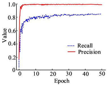
b) Changes in model precision and recall
The model’s loss value steadily stabilizes at the start of the tenth training cycle, as seen in Fig. 10(a), where the model’s loss in the training set changes in a declining pattern as the number of training rounds increases. In comparison to the training set, the model’s overall loss value drops and its change in loss value is very variable in the validation set. In Fig. 10(b), the recall rate rises as the number of training rounds increases and steadily stabilizes at 25 training rounds, whereas the precision rate of the model varies less as the number of training rounds increases. In the meantime, the study further contrasts the performance of the suggested model with that of the already accepted IC model; the comparison's findings are displayed in Fig. 11.
Fig. 11(a) shows the comparison of the Recipient Operating Characteristics (ROC) curves of the three models, with False Positive Rate (FPR) in the horizontal coordinate and True Positive Rate (TPR) in the vertical coordinate. The comparison shows that the ROC curve of the model proposed in the study has a better TPR score than the other two models, while the curve of the CNN is closer to the test curve, which indicates that the FPR of the CNN is higher. In Fig. 11(b), with the increase of training rounds, the F1 values of all three models show an increasing trend, among which the research-proposed IC model has the highest F1 value, which is as high as 98.972 % after 50 rounds of training, which is an increase of 27.457 % and 14.482 % than the other two models, respectively. It indicates that the IC model proposed in the study is more effective than the single algorithm IC in CR and detection, and it has more applications in ABCC recognition and D-D.
Fig. 11Performance comparison of different image classification models
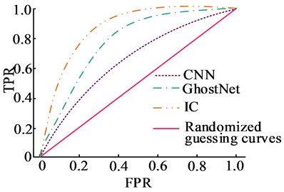
a) ROC for three model
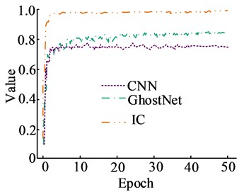
b) Changes in model F1 score
Table 2Comparison of detection performance and results of different methods
Method | AP (%) | mAP (%) | Confidence level | Confidence interval | FPS | ||
Test set | Validation set | Training set | |||||
CNN | 84.85 | 72.80 | 71.63 | 76.43 | 0.94 | (69.11, 83.74) | 26.60 |
GhostNet | 89.34 | 78.49 | 87.54 | 85.12 | 0.94 | (79.31, 94.94) | 36.70 |
IC | 94.87 | 88.76 | 93.21 | 92.28 | 0.95 | (89.12, 95.44) | 35.60 |
The performance validation results of the three methods on the ABCCD dataset are shown in Table 2. Where AP is the average precision, nAP denotes the mean average precision, and FPS denotes the number of transmitted frames per second. It can be seen that the mAP value of IC is 92.28 %, which is 20.74 % and 8.41 % more than the other two models, respectively, which indicates that IC has better crack recognition in the ABCCD dataset. Comparing the sensitivity of the three methods, it can be seen that the FPS value of IC is 35.60, which is lower than GhostNet but increased by 37.97 % than CNN. Therefore, IC is able to recognize the component cracks better while ensuring crack recognition. In addition, the confidence level of IC detection is 0.95 and its confidence interval is (89.12, 95.44), which indicates that the proposed method has some feasibility in component crack recognition and detection, and the study utilizes the ABCCD dataset for the model performance validation with reliability.
4.3. Experimental validation of crack measurements
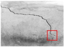
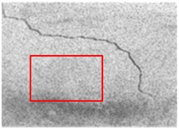
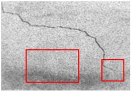
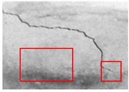
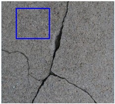
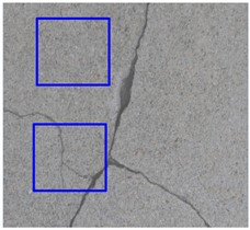
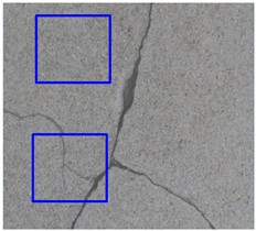
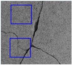
To verify the validity and practicability of the CR and D-D methods proposed in the study, the study conducted crack measurement experiments based on the ABCCD dataset. Firstly, three concrete walls of the same type as ABCC were selected as the experimental materials, and the QR Code size was set to 25×25 mm2 as shown in Fig. 12.
Fig. 12Image of the crack to be detected
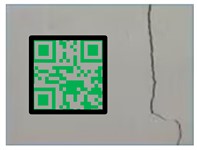
a) Crack A
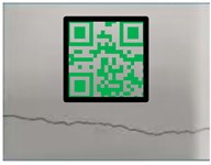
b) Crack B
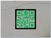
c) Crack C
Fig. 12(a), (b) and (c) show three selected concrete wall panel cracks, which are named as Crack C, Crack B and Crack A respectively in order, with the same naming sequence of QR Code tags. Based on the image of the cracks to be tested in Fig. 12, they were image preprocessed using the CIP algorithm proposed in the study, followed by identification and detection using the IC model. The results of the maximum length and width detection of all cracks compared with the actual measurements are shown in Table 3.
Table 3Crack maximum length and width detection results
Crack number | Calibration ratio (mm/pixel) | Maximum length | Maximum width | ||||||||
Pixel | Calculated value (mm) | Measured value (mm) | Absolute error (mm) | Relative error (%) | Pixel | Calculated value (mm) | Measured value (mm) | Absolute error (mm) | Relative error (%) | ||
Crack A | 0.019 | 4319.000 | 80.331 | 75.000 | 5.331 | 7.108 | 45.000 | 0.837 | 0.800 | 0.037 | 4.625 |
Crack B | 0.018 | 5060.000 | 89.564 | 85.000 | 4.564 | 5.369 | 30.000 | 0.531 | 0.500 | 0.031 | 6.200 |
Crack C | 0.017 | 6041.000 | 101.490 | 95.000 | 6.490 | 6.832 | 28.000 | 0.470 | 0.440 | 0.030 | 6.818 |
In Table 3, the differences between the CR and D-D methods proposed by the study and the actual measurements are small, and the relative errors of the maximum length of the three cracks are in the range of 4.564 %-6.490 %, while the relative errors of the maximum width are in the range of 4.625 %-6.818 %. This indicates that the detection method proposed by the study is more reliable and similar to the actual measurement results. Overall, the detection accuracy of the CR and D-D methods proposed by the study is better and with less error from the actual, which can satisfy the D-D of ABCC and also reduce the limitations of external conditions such as manual inspection. In terms of locating the maximum length and width of cracks, the detection method proposed by the study is more superior and more accurate in locating the maximum crack point.
5. Discussion
The study explored for ABCC and the experimental validation showed that the CIP algorithm has superior denoising effect in image processing, and the proposed CR and D-D method has a high value of application in AB. The study by N. Safaei et al. also confirmed that denoising crack images can improve the recognition accuracy of crack images [30]. And the strategy of M. Woźniak and K. Woźniak to localize crack images using QR technique further confirms the feasibility of studying the introduction of QR technique in surface CR and D-D method [31]. However, it was found that the detection method can only be used for crack identification and detection if the planar shot is parallel to the build, but in practice it is not possible to ensure that the crack images of each assembled building are in the planar state. Therefore, the effects of shadows and noise on concrete surface cracks are still a great challenge for research to explore. Relevant scholars have used shadow removal as an orientation for the shadow processing of crack images, while for the problem of uneven illumination in the image background, adaptive image thresholding with local first-order statistics, histogram equalization, and noise filtering with nonlinear diffusion filtering have been used for image processing [32-33]. The above techniques might be considered to be applied in the next step of the research.
It is worth mentioning that background color, concrete structure type, texture, and illumination all have an impact on the identification and calibration of concrete cracks. Y. Liu and M. Gao et al. found that the concrete structure type affects the accuracy of crack identification on the surface in performing concrete crack detection [34]. S. Bang et al. found that the background of the captured image as well as the illumination also have an impact on the cracks on the surface of the concrete structure image feature extraction [35]. Similarly, in the validation of surface CR and D-D method, it was found that the limitations of image background, illumination, texture, and component type can have a negative effect on the recognition of concrete cracks, and the specific conditions of the captured images should be considered in the image processing. However, the study did not further optimize the background color, illumination, etc. in depth during the detection process. Therefore, subsequent consideration will be given to designing relevant algorithms to correct the captured images, or utilizing a shooting support platform such as a gimbal to deflate the shooting deviation.
6. Conclusions
To address the dilemma that visually-assisted surface D-D techniques cannot be directly applied to ABCC recognition and D-D, the study proposes a surface CR and D-D method for intelligent construction. The validation of the CIP algorithm revealed that the PSNR value of CIP increased by 111.421 % and the SSIM value increased by 5.500 compared to the conventional BF. After 50 training rounds, the F1 value grew by 27.457 % and 14.482 %, respectively, compared to other models, according to the validation of the IC model, which also revealed that the suggested model had lower loss values in the training and test sets. Detection method experiments revealed that the accuracy of the proposed method in CR of concrete wall panels is superior and its detection accuracy is high, with a relative error of less than 10 % from the actual measurement, and an absolute error of about 6 mm for the detection of the maximum length of cracks. The results show that the proposed CR and D-D methods have high application value in crack detection in AB construction, and their detection accuracy is superior compared with traditional manual measurement, and they are not limited and interfered by factors such as manual experience, and the QR Code pixel localization technique is more ideal for the measurement of cracks. However, it is found that the component crack images during the experimental process are limited by the shooting angle, background, and illumination, which can lead to a decrease in the recognition accuracy of the cracks. In the future, the design of image correction algorithms will be considered, and the introduction of shooting equipment such as a gimbal and other support platforms for the correction and processing of crack images will be considered, with a view to reducing the influence of shadows, background and other factors on ABCC, so as to realize highly efficient ABCC detection.
References
-
J. Yu, A. Chan, B. Wang, Y. Liu, and J. Wang, “A mixed-methods study of the critical success factors in the development of assembled buildings in steel structure projects in China,” International Journal of Construction Management, Vol. 23, No. 13, pp. 2288–2297, Oct. 2023, https://doi.org/10.1080/15623599.2022.2052429
-
C. Lendel and N. Solin, “Protein nanofibrils and their use as building blocks of sustainable materials,” RSC Advances, Vol. 11, No. 62, pp. 39188–39215, Dec. 2021, https://doi.org/10.1039/d1ra06878d
-
Z. Huo, Y. Bai, and X. Li, “Preparation of expanded graphite and fly ash base high temperature compound phase transition heat absorption material and its application in building temperature regulation,” Science of Advanced Materials, Vol. 12, No. 6, pp. 829–841, Jun. 2020, https://doi.org/10.1166/sam.2020.3745
-
Z. Zhou, J. Zhang, and C. Gong, “Automatic detection method of tunnel lining multi‐defects via an enhanced you only look once network,” Computer-Aided Civil and Infrastructure Engineering, Vol. 37, No. 6, pp. 762–780, Mar. 2022, https://doi.org/10.1111/mice.12836
-
Y. Wu, Y. Qin, Y. Qian, F. Guo, Z. Wang, and L. Jia, “Hybrid deep learning architecture for rail surface segmentation and surface defect detection,” Computer-Aided Civil and Infrastructure Engineering, Vol. 37, No. 2, pp. 227–244, Jun. 2021, https://doi.org/10.1111/mice.12710
-
R. Rai, M. K. Tiwari, D. Ivanov, and A. Dolgui, “Machine learning in manufacturing and industry 4.0 applications,” International Journal of Production Research, Vol. 59, No. 16, pp. 4773–4778, Aug. 2021, https://doi.org/10.1080/00207543.2021.1956675
-
R. Dave and J. Purohit, “Leveraging deep learning techniques to obtain efficacious segmentation results,” Archives of Advanced Engineering Science, Vol. 1, No. 1, pp. 11–26, Jan. 2023, https://doi.org/10.47852/bonviewaaes32021220
-
J. Jing, Z. Wang, M. Rätsch, and H. Zhang, “Mobile-Unet: An efficient convolutional neural network for fabric defect detection,” Textile Research Journal, Vol. 92, No. 1-2, pp. 30–42, May 2020, https://doi.org/10.1177/0040517520928604
-
R. Gai, N. Chen, and H. Yuan, “A detection algorithm for cherry fruits based on the improved YOLO-v4 model,” Neural Computing and Applications, Vol. 35, No. 19, pp. 13895–13906, May 2021, https://doi.org/10.1007/s00521-021-06029-z
-
P. Bergmann, K. Batzner, M. Fauser, D. Sattlegger, and C. Steger, “The MVTec anomaly detection dataset: a comprehensive real-world dataset for unsupervised anomaly detection,” International Journal of Computer Vision, Vol. 129, No. 4, pp. 1038–1059, Jan. 2021, https://doi.org/10.1007/s11263-020-01400-4
-
P.J. Chun, S. Izumi, and T. Yamane, “Automatic detection method of cracks from concrete surface imagery using two‐step light gradient boosting machine,” Computer-Aided Civil and Infrastructure Engineering, Vol. 36, No. 1, pp. 61–72, May 2020, https://doi.org/10.1111/mice.12564
-
X. Ni, Z. Ma, J. Liu, B. Shi, and H. Liu, “Attention Network for Rail Surface Defect Detection via Consistency of Intersection-over-Union(IoU)-Guided Center-Point Estimation,” IEEE Transactions on Industrial Informatics, Vol. 18, No. 3, pp. 1694–1705, Mar. 2022, https://doi.org/10.1109/tii.2021.3085848
-
C. Ngaongam, M. Ekpanyapong, and R. Ujjin, “Surface crack detection by using vibrothermography technique,” Quantitative InfraRed Thermography Journal, Vol. 20, No. 5, pp. 292–303, Oct. 2023, https://doi.org/10.1080/17686733.2022.2121102
-
J. Tao, Y. Zhu, W. Liu, F. Jiang, and H. Liu, “Smooth surface defect detection by deep learning based on wrapped phase map,” IEEE Sensors Journal, Vol. 21, No. 14, pp. 16236–16244, Jul. 2021, https://doi.org/10.1109/jsen.2021.3076610
-
K. Qiu, L. Tian, and P. Wang, “An effective framework of automated visual surface defect detection for metal parts,” IEEE Sensors Journal, Vol. 21, No. 18, pp. 20412–20420, Sep. 2021, https://doi.org/10.1109/jsen.2021.3095410
-
E. Mohammed Abdelkader, “On the hybridization of pre-trained deep learning and differential evolution algorithms for semantic crack detection and recognition in ensemble of infrastructures,” Smart and Sustainable Built Environment, Vol. 11, No. 3, pp. 740–764, Nov. 2022, https://doi.org/10.1108/sasbe-01-2021-0010
-
X. Chen, J. Li, S. Huang, H. Cui, P. Liu, and Q. Sun, “An automatic concrete crack-detection method fusing point clouds and images based on improved otsu’s algorithm,” Sensors, Vol. 21, No. 5, p. 1581, Feb. 2021, https://doi.org/10.3390/s21051581
-
Z. Zhao, B. Xiong, L. Wang, Q. Ou, L. Yu, and F. Kuang, “RetinexDIP: A unified deep framework for low-light image enhancement,” IEEE Transactions on Circuits and Systems for Video Technology, Vol. 32, No. 3, pp. 1076–1088, Mar. 2022, https://doi.org/10.1109/tcsvt.2021.3073371
-
A. Shah et al., “Comparative analysis of median filter and its variants for removal of impulse noise from gray scale images,” Journal of King Saud University – Computer and Information Sciences, Vol. 34, No. 3, pp. 505–519, Mar. 2022, https://doi.org/10.1016/j.jksuci.2020.03.007
-
A. Paul, “Adaptive tri-plateau limit tri-histogram equalization algorithm for digital image enhancement,” The Visual Computer, Vol. 39, No. 1, pp. 297–318, Nov. 2021, https://doi.org/10.1007/s00371-021-02330-z
-
W. Zhang, Y. Wang, and C. Li, “Underwater image enhancement by attenuated color channel correction and detail preserved contrast enhancement,” IEEE Journal of Oceanic Engineering, Vol. 47, No. 3, pp. 718–735, Jul. 2022, https://doi.org/10.1109/joe.2022.3140563
-
Z. Tang, L. Jiang, and Z. Luo, “A new underwater image enhancement algorithm based on adaptive feedback and Retinex algorithm,” Multimedia Tools and Applications, Vol. 80, No. 18, pp. 28487–28499, Jun. 2021, https://doi.org/10.1007/s11042-021-11095-5
-
M. Lecca, G. Gianini, and R. P. Serapioni, “Mathematical insights into the original Retinex algorithm for image enhancement,” Journal of the Optical Society of America A, Vol. 39, No. 11, p. 2063, Nov. 2022, https://doi.org/10.1364/josaa.471953
-
J. R. Jebadass and P. Balasubramaniam, “Low light enhancement algorithm for color images using intuitionistic fuzzy sets with histogram equalization,” Multimedia Tools and Applications, Vol. 81, No. 6, pp. 8093–8106, Jan. 2022, https://doi.org/10.1007/s11042-022-12087-9
-
F. Bulut, “Low dynamic range histogram equalization (LDR-HE) via quantized Haar wavelet transform,” The Visual Computer, Vol. 38, No. 6, pp. 2239–2255, Aug. 2021, https://doi.org/10.1007/s00371-021-02281-5
-
Y. Tao, F. Cai, G. Zhan, H. Zhong, Y. Zhou, and S. Shen, “Floating quick response code based on structural black color with the characteristic of privacy protection,” Optics Express, Vol. 29, No. 10, p. 15217, May 2021, https://doi.org/10.1364/oe.423923
-
G. Niu, Q. Yang, Y. Gao, and M.-O. Pun, “Vision-based autonomous landing for unmanned aerial and ground vehicles cooperative systems,” IEEE Robotics and Automation Letters, Vol. 7, No. 3, pp. 6234–6241, Jul. 2022, https://doi.org/10.1109/lra.2021.3101882
-
R. Kononchuk, J. Cai, F. Ellis, R. Thevamaran, and T. Kottos, “Exceptional-point-based accelerometers with enhanced signal-to-noise ratio,” Nature, Vol. 607, No. 7920, pp. 697–702, Jul. 2022, https://doi.org/10.1038/s41586-022-04904-w
-
Y. Lustig et al., “Potential antigenic cross-reactivity between severe acute respiratory syndrome coronavirus 2 (SARS-CoV-2) and dengue viruses,” Clinical Infectious Diseases, Vol. 73, No. 7, pp. e2444–e2449, Oct. 2021, https://doi.org/10.1093/cid/ciaa1207
-
N. Safaei, O. Smadi, A. Masoud, and B. Safaei, “An automatic image processing algorithm based on crack pixel density for pavement crack detection and classification,” International Journal of Pavement Research and Technology, Vol. 15, No. 1, pp. 159–172, Jun. 2021, https://doi.org/10.1007/s42947-021-00006-4
-
M. Woźniak and K. Woźniak, “MarQR technology for measuring relative displacements of building structure elements with regard to joints and cracks,” Walter de Gruyter GmbH, Reports on Geodesy and Geoinformatics, Jun. 2020.
-
L. Fan, S. Li, Y. Li, B. Li, D. Cao, and F.-Y. Wang, “Pavement cracks coupled with shadows: A new shadow-crack dataset and a shadow-removal-oriented crack detection approach,” IEEE/CAA Journal of Automatica Sinica, Vol. 10, No. 7, pp. 1593–1607, Jul. 2023, https://doi.org/10.1109/jas.2023.123447
-
A. M. Parrany and M. Mirzaei, “A new image processing strategy for surface crack identification in building structures under non‐uniform illumination,” IET Image Processing, Vol. 16, No. 2, pp. 407–415, Oct. 2021, https://doi.org/10.1049/ipr2.12357
-
Y. Liu and M. Gao, “Detecting cracks in concrete structures with the baseline model of the visual characteristics of images,” Computer-Aided Civil and Infrastructure Engineering, Vol. 37, No. 14, pp. 1891–1913, Jun. 2022, https://doi.org/10.1111/mice.12874
-
S. Bang, S. Park, H. Kim, and H. Kim, “Encoder-decoder network for pixel‐level road crack detection in black‐box images,” Computer-Aided Civil and Infrastructure Engineering, Vol. 34, No. 8, pp. 713–727, Feb. 2019, https://doi.org/10.1111/mice.12440
About this article

The research is supported by Fund projects: Yan’an Science and Technology Plan Project, Application and research of prefabricated building, (No. SL2022SLZDCY-005); Yan’an University 2023 Research Special Project, Experimental Study on the Performance of Coal Gangue Insulation Material in Assembly Building in Northern Shaanxi Province (No. 2023JBZR-001).
The datasets generated during and/or analyzed during the current study are available from the corresponding author on reasonable request.
Zhipeng Huo collected the samples. Xiaoqiang Wu analysed the data. Tao Cheng conducted the experiments and analysed the results. All authors discussed the results and wrote the manuscript
The authors declare that they have no conflict of interest.
