Abstract
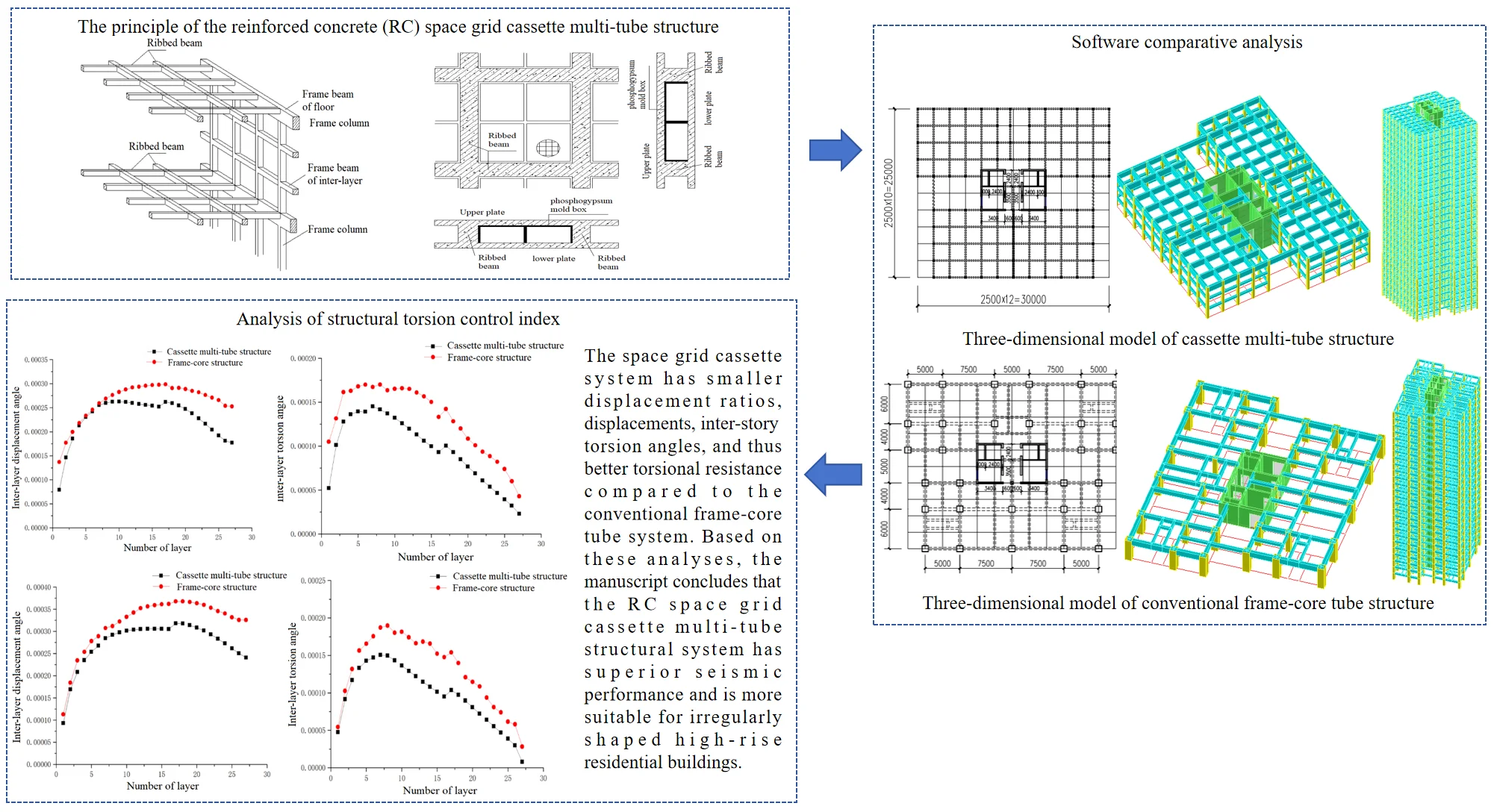
The manuscript introduces a new structural system called the reinforced concrete (RC) space grid cassette multi-tube structure for high-rise buildings. A case study building is analyzed using this system and compared to a conventional RC frame-core tube structure. Through modal analysis in the software “Midas Gen”, the torsional effect and control indices like inter-story displacement ratio, maximum displacement, etc. are compared between the two structural systems. The results show that the space grid cassette system has smaller displacement ratios, displacements, inter-story torsion angles, and thus better torsional resistance compared to the conventional frame-core tube system. Based on these analyses, the manuscript concludes that the RC space grid cassette multi-tube structural system has superior seismic performance and is more suitable for irregularly shaped high-rise residential buildings.
Highlights
- A new structural system called the reinforced concrete (RC) space grid cassette multi-tube structure for high-rise buildings have been introduced.
- As for the torsion cycle ratio, there are some unreasonable points in the code, which is easy to cause designers to misunderstand the code and is made big mistakes in the design, so it is urgent to find a new control index to control the structural torsion.
- The space grid cassette system has smaller displacement ratios, displacements, inter-story torsion angles, and thus better torsional resistance compared to the conventional frame-core tube system.
- The RC space grid cassette multi-tube structural system has superior seismic performance and is more suitable for irregularly shaped high-rise residential buildings.
1. Introduction
Many buildings are designed as “irregular building structures” at present. However, structural engineers require the layout of building structures to be simple and regular, especially for high-rise and large-span building structures within the seismic zone. Buildings and structures with irregular structural plane and facade layout are severely damaged locally under the action of a large earthquake, and some buildings and structures even have fallen down as a whole. Due to the damage caused by the earthquake, lives and property of people have suffered incalculable losses [1]. Therefore, researchers have conducted various studies on the structures to improve the comprehensive performance of the structure [2-10]. The LCCA-based probabilistic optimization of a 3D RC structure is using by Varaee, the lifetime repair costs can be reduced by 12 % and the total construction costs can be reduced by 8.5 % [2]. Es-Haghi proposed a new algorithm, for solving optimization problems of steel frames, the algorithm decreases the total weight of regular and irregular steel frame about 11.1 % and 26.4 % in comparing with the optimized results of SAP2000, respectively [3]. Shishegaran proposed a new technique and a reinforcement bar system to increase the flexural capacity of simply supported reinforced concrete beams, and an equation is formulated to calculate bending capacity of a new reinforcement bar system beam [4]. Shishegaran developed a transferred stress system (TSS) on longitudinal reinforcement bars for increasing the bending capacity of RC frames, the load carrying capacity and ductility of TSS fixed beam are 29.39 % and 23.69 % higher compared to those of the ordinary fixed beams [5]. Fahiminia evaluated the dynamic behavior of a developed bypass viscous damper, seismic behaviors of nonstructural masonry claddings are also compared in the cases of hospital structure with and without dampers [6]. Rabczuk investigated the resistance of reinforced concrete panels (RCPs) due to explosive loading using nonlinear finite element analysis and surrogate models [7]. Pany dealt with the radial vibration of a row of cylindrical panels of finite length [8], and flutter analysis of periodically supported cylindrically curved panels [9] using the concept of wave propagation in periodic structures. Propagation of waves along the axis of the cylindrically curved panels of infinite length, supported at regular intervals is considered by Pany to determine their natural frequencies in bending vibration [10]. Pany described the propagation of free waves in a two-dimensional periodic plate using the finite element (FE) method, the current PS-FEM approach can be used to generate dispersion relations with reasonable accuracy [11].
Large numbers studies of earthquake damage have shown that earthquake action is highly susceptible to causing seismic damage to irregular structures [12]-[13]. Irregular planes and facades of structures are prone to torsional brittle failure, structures are exhibited obvious torsional failure characteristic, and in severe cases, structures even have fallen down as a whole. For this reason, structural engineers conduct reasonable torsional design for irregular structures on the plane and facade, and analyze the torsional effect of the structure. It is one of the important means to improve the seismic safety of structures. So researchers on torsion of high-rise structures have received widespread attention from researchers from various countries [14]-[17].
In order to improve the torsional performance of high-rise irregular structures, a new structural system - “space grid cassette structure” – has been proposed by Academician Kejian Ma’s team from the Space Structures Research Center of Guizhou University [18]-[20]. The space grid cassette structure includes the reinforced concrete space grid cassette structure [21] and the assembled integral steel cassette structure [22]. According to the characteristics of space grid cassette structure, a high-rise residential building which is made of phosphogypsum is constructed in the phosphorus chemical industry base of Xiangyang City, Hubei Province. Each household has a large hollow plate, and the industrial gypsum prefabricated block is used to divide the living room flexibly, which can meet demand of people for large rooms in residential rooms and form a reinforced concrete space grid cassette multi-tube structure. This article is analyzed the torsional effect of reinforced concrete space grid cassette multi-tube structures and conventional frame-core tube structures, which is concluded that the reinforced concrete space grid cassette multi-tube structure has better torsional performance compared to conventional frame-core tube structure, which is more suitable for high-rise residential buildings.
2. Space grid cassette multi-tube structure
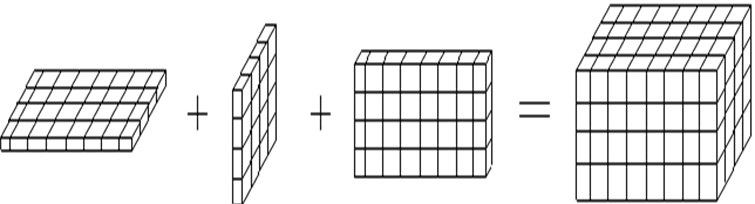
The space grid cassette structure is inspired by the chalk box in the school. The front, back, left, and right sides of the chalk box are equivalent to the outer walls of the space grid cassette structure. The upper and lower sides of the chalk box are equivalent to the floor plates of the space grid cassette structure (Fig. 1). And dozens of chalk boxes are stacked up to form the high-rise building of space grid cassette structure.
Fig. 1Cassette structure composed of beamless grid hollow plate and grid wall frame
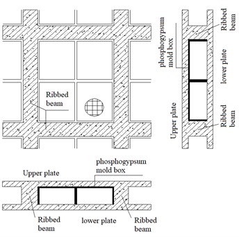
The smaller spacing between beams and columns in the space grid cassette structure wall frame compared to conventional frame structures to fill the grid wall frame with cast-in-place industrial gypsum. The floor is a large hollow plate without beam in a grid mesh format, and which is filled with phosphogypsum mold boxes [23]. Finally, the grid wall frame and the large hollow plate are combined to form a space grid cassette structure (Fig. 2, 3), and dozens of grid cassette structures are stacked up to form the high-rise building of space grid cassette structure. The outer four box cylinders are connected with the middle core cylinder, the floor beam, the Inter-layer beam and the hollow plate to form the space grid cassette multi-tube structure.
Fig. 2Schematic diagram of grid floor and grid wall frame
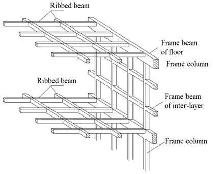
Fig. 3Grid hollow plate
The vertical force of the space grid cassette multi-tube structure is borne and transmitted by phosphogypsum filled walls, space grid walls, reinforced concrete shear walls, and large hollow plates, while the horizontal force is borne by reinforced concrete shear walls, space grid walls, and phosphogypsum filled walls.
3. Calculation model and design parameters
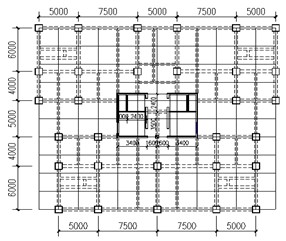
The floor plan size of this project is 30.0 m × 25.0 m, inner tube size is 10.0 m × 5.9 m, with 2 underground floors and 26 above ground floors. Height of the standard floor is 3.1 m, and height of the structural eaves is 80.6 m. The elevation of the roof of the local elevator room is 83.7 m.
3.1. Model of space grid cassette multi-tube structure
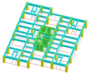
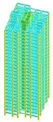
The model of space grid cassette multi-tube structure is established in accordance with the latest standards of “Code for Seismic Design of Buildings” (GB50011-2010) [24] and “Technical Specification for Concrete Structures of Tall Buildings” (JGJ3-2010) [25]. The design parameters of each component of the structural model are shown in Table 1. Standard floor plan, standard floor axonometric view, and three-dimensional view, as shown in Fig. 4.
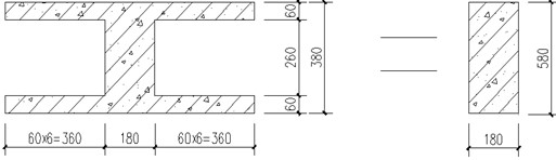
The floor is composed of four grid shaped hollow plates without beams, as well as ordinary floor plates. The grid size of hollow plates is 2.5 m×2.5 m. The length of the short span of the floor is 10.0 m, and the thickness of plate is calculated as 1/30 of the short span length. So thickness of plate 10000 / 30 = 333.33 mm, and the thickness of plate is taken as 380 mm. The thickness of the upper and lower layers of the grid shaped hollow plate is 60 mm, and 4 phosphogypsum mold boxes are placed in each grid, and each phosphogypsum mold box is weighed 25 kg. In order to facilitate the software design and calculation, the method of equal generation of well-shaped beam is adopted for the hollow plate [26]. The grid shaped hollow plate is dispersed into the cross-beam system roof, and the flange of the cross beams is taken 6 times the thickness of the plates to form an I-shaped beam [27]. According to the principle of equal bending stiffness, the I-beam is replaced by a rectangular beam, 302844 cm4, the width of the hollow plate rib beam is 180 mm, = 586.6 mm, then after conversion, the height of beam is 580 mm (Fig. 5).
Table 1Sectional dimension of cassette multi-tube structural members
Component type | Number | Dimension / mm | Number of floors | Strength grade of concrete | Reinforced | Stirrup |
Column | 1 | 500×500 | 1-6 | C40 ( 26.8 MPa) | HRB400 (yield strength is 400 MPa) | HPB300 (yield strength is 300 MPa) |
2 | 450×450 | 7-16 | C40 ( 26.8 MPa) | |||
3 | 350×350 | 17-26 | C35 ( 23.4 MPa) | |||
4 | 300×300 | 27 | C35 ( 23.4 MPa) | |||
Floor beam | 1 | 300×500 | 1-26 | C30 ( 20.1 MPa) | ||
Inter-layer beam | 2 | 250×200 | 1-26 | C30 ( 20.1 MPa) | ||
Shear wall | 1 | 400 | 1-16 | C40 ( 26.8 MPa) | ||
2 | 350 | 17-26 | C35 ( 23.4 MPa) | |||
3 | 300 | 27 | C35 ( 23.4 MPa) | |||
4 | 200 | 1-27 | C40 ( 26.8 MPa) |
Fig. 4Three-dimensional model of cassette multi-tube structure
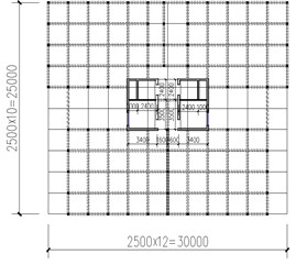
a) Standard floor plan
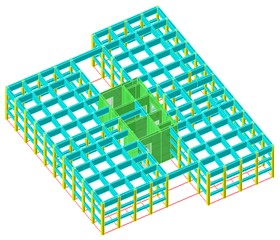
b) Standard layer axonometry
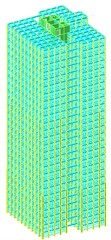
c) 3D Finite element model
Fig. 5Convert I-beam to rectangular beam (unit: mm)
3.2. Model of frame-core tube structures
In order to compare with the space grid cassette multi-tube structure effectively, the size of the core tube of the conventional frame-core tube structure is the same as that of the space grid cassette multi-tube structure, the minimum column spacing is 4 m and the maximum column spacing is 7.5 m. Based on the principle that the axial compression ratio of the column of the frame-core tube structure is the same as that of the column of the space grid cassette multi-tube structure, the column size of the frame-core tube structure is also divided into three changes, The design parameters of each component of the structural model are shown in Table 2. Standard floor plan, standard floor axonometric view, and three-dimensional view, as shown in Fig. 6.
Table 2Sectional dimension of conventional frame-core tube structural members
Component type | Number | Dimension /mm | Number of floors | Strength grade of concrete | Reinforced | Stirrup |
Column | 1 | 950×950 | 1 | C40 ( 26.8 MPa) | HRB400 (yield strength is 400 MPa) | HPB300 (yield strength is 300 MPa) |
2 | 900×900 | 1-6 | C40 ( 26.8 MPa) | |||
3 | 800×800 | 7-16 | C40 ( 26.8 MPa) | |||
4 | 700×700 | 17-27 | C35 ( 23.4 MPa) | |||
Beam | 1 | 400×800 | 1-6 | C30 ( 20.1 MPa) | ||
2 | 400×750 | 7-16 | C30 ( 20.1 MPa) | |||
3 | 400×700 | 17-26 | C30 ( 20.1 MPa) | |||
4 | 350×700 | 1-16 | C30 ( 20.1 MPa) | |||
5 | 400×650 | 1-26 | C30 ( 20.1 MPa) | |||
6 | 300×650 | 1-26 | C30 ( 20.1 MPa) | |||
7 | 300×600 | 1-27 | C30 ( 20.1 MPa) | |||
8 | 300×500 | 1-26 | C30 ( 20.1 MPa) | |||
9 | 250×450 | 1-26 | C30 ( 20.1 MPa) | |||
Shear wall | 1 | 400 | 1-16 | C40 ( 26.8 MPa) | ||
2 | 350 | 17-26 | C35 ( 23.4 MPa) | |||
3 | 300 | 27 | C35 ( 23.4 MPa) | |||
4 | 200 | 1-27 | C40 ( 26.8 MPa) |
Fig. 6Three-dimensional model of conventional frame-core tube structure
a) Standard floor plan
b) Standard layer axonometry
c) 3D Finite element model
3.3. Software applicability analysis
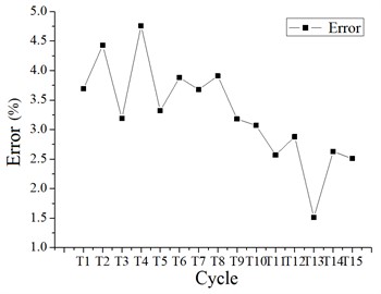
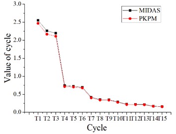
In this article, dimensions of each component in the two structural models are calculated by the calculation and analysis software “PKPM” to obtain data that is met the actual engineering requirements. Then “MIDAS-Gen” software is used to analyze the basic mechanical properties of the two structures. By conducting static analysis on the models in the two types of software, and models of first 15 order cycles and structural mass are compared (Fig. 7, 8), it can be concluded that the model in “MIDAS Gen” software is accurate and can be used for the next step of analysis.
It can be seen that the cycle of the cassette multi-tube structure model calculated by the two software is relatively close, and the maximum relative error of the cycle is 4.76 %, both of which are less than 5 %. And it can be seen that the cycle of the frame-core tube structure model calculated by the two software is also relatively close, and the maximum relative error of the cycle is 4.40 %, both of which are less than 5 %. It is indicated that the calculation results are accurate, and the modeling in “MIDAS Gen” can be directly used the component dimensions which are obtained by “PKPM” software.
In Table 3, M1 is the total mass generated by dead load, M2 is the total mass generated by live load, and M3 is the total mass of the structure. It can be seen that the quality of the cassette multi-tube structure model calculated by the two software is relatively close, and the quality error is less than 4 %. And it can be seen that the quality of the frame-core tube structure model calculated by the two software is also relatively close, and the quality error is less than 3 %. It is shown that the model is more accurate in “MIDAS-Gen” software.
Fig. 7Two kinds of software calculate the first 15 order cycles of cassette multi-tube structure and the relative error of cycles
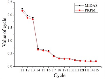
a) The first 15 order cycles which are calculated by two kinds of software
b) The relative error of cycles which are calculated by two kinds of software
Fig. 8Two kinds of software calculate the first 15 order cycles of frame-core tube structure and the relative error of cycles
a) The first 15 order cycles which are calculated by two kinds of software
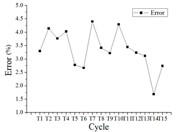
b) The relative error of cycles which are calculated by two kinds of software
Table 3Structural quality error
Model of cassette multi-tube structure | Model of frame-core tube structure | ||||||
Quality (t) | MIDAS | PKPM | Error (%) | Quality (t) | MIDAS | PKPM | Error (%) |
M1 | 20173.53 | 19722.75 | 2.23 | M1 | 24325.13 | 23874.61 | 1.82 |
M2 | 2551.58 | 2630.157 | -3.08 | M2 | 1815.05 | 1761.27 | 2.96 |
M3 | 22725.11 | 22352.92 | 1.64 | M3 | 26140.18 | 25635.88 | 1.93 |
Based on the comparison of cycle and structure quality of cassette multi-tube structure and frame-core structure model in “PKPM” software and “MIDAS-Gen” software respectively, it can be seen that the modeling of cassette multi-tube structure and frame-core structure in “MIDAS-Gen” software is accurate, and can be analyzed in the next step.
3.4. Design parameters
In this project, it is assumed that the embedded end of the structure is at the top of the basement, so the model is only included the part above the ground. The fortification earthquake group is the first group, the fortification intensity is 6 degrees, the site category is class II, the basic wind pressure is 0.35 KN/m2, the characteristic period 0.35 s, and the structural damping ratio is 0.05, the periodic reduction coefficient is 0.8, the accidental eccentric and bidirectional earthquake is considered, the formation combination method is CQC, and the number of formations is calculated as 26, the influence of higher order modes is considered. The constant load on the floor is 2.5 KN/m2 (excluding the dead-weight of the grid shaped hollow plate), the dead-weight of the external wall is equivalent to the line load of 6.5 KN/m, the partition wall is calculated according to the equivalent uniform load on the floor, and the total live load on the floor is 3.5 KN/m2.
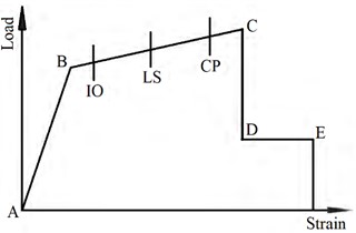
In this paper, the software “MIDAS-Gen” is used to perform static elastic-plastic analysis of the new structure under rare earthquakes to be evaluated the torsional resistance of the structure. In the model, beam elements are used for beams and columns, and wall elements are used for shear walls. Steel bars are automatically imported and generated by the program after calculating the internal forces of each component of the structure through modal decomposition response spectrum analysis and reinforcement. The beam hinge is defined as the bending moment-rotation angle, the correlation type is “none”, components are My and Mz, the position distribution of the hinge is “I end” and “J end”, the skeleton curve is of “FEMA” type, the material type is “concrete”, and the unit type is “beam”. The column hinge is defined as bending moment-rotation angle, the correlation type is “P-M-M” type, components are My and Mz, the position distribution of hinge is “I end” and “J end”, the skeleton curve is of “FEMA” type, the material type is “concrete”, and the element type is “column”. The wall hinge is defined as the bending moment-rotation angle, the related type is “P-M-M”, components are Fz, My and Mz, the position distribution of the hinge is “I end” and “J end”, the skeleton curve is of “FEMA” type, the material type is “concrete”, and the unit type is “wall”, the unit model of the wall is adopted the plate unit model. Component skeleton curve in Fig. 9.
Fig. 9Component skeleton curves
4. Analysis of structural torsion control index
4.1. The problem of torsion control in Chinese standard
In the latest standards of “Code for Seismic Design of Buildings” (GB50011-2010) and “Technical Specification for Concrete Structures of Tall Buildings” (JGJ3-2010), Both of them are put forward some requirements and specific judgment indicators for the torsion control of structures. But there are some differences between the two specifications in some regulations, mainly in the judgment indicators of irregular torsion and the consideration of accidental eccentricity (Table 4).
Due to different regulations of China on torsion control, the same structure may be classified as a regular structure when it is calculated according to the “Code for Seismic Design of Buildings”, while it may be classified as an irregular structure when it is calculated according to the “Technical Specification for Concrete Structures of Tall Buildings”. This situation is due to the fact that the regular structure may be classified into the irregular structure because of the torsional rigidity is not enough to meet the requirements of the torsional displacement ratio, so that the division is unreasonable from the principle. And the accidental eccentricity is objective, and it will be affected the torsional effect of the structure, it will not be changed due to the structural form.
The torsional period ratio is referred to the ratio of the first natural vibration period which is based on torsion to the first natural vibration period which is based on translation, that is /. The control index of torsional period ratio will be given the designer an illusion that the structure is safe if the ratio is within the requirements of the specification. When the ratio is failed to meet the requirements of the standard, the structural designer will simply to reduce the value of or to expand the value of , without considering the adverse effects of changing the value of and on other aspects of the structure. It is unreasonable and unsafe to be caused the torsional rigidity of the structure to be too large, the size of the external component of the structure to be too large and the internal component to be too small, or to be made the size of the component smaller in the first translational direction to be met the requirements of the specification [28]. For example, for a frame structure that is met the requirements of torsional period ratio, if other conditions are consistent, shear walls be arranging in the middle of the structure should be more safely in general, but the torsional period ratio will be became difficult to be met the requirements of the specification, which is indicated that the torsional period ratio is unreasonable in certain situations. Therefore, it can be seen that there are some problems in the indicators of torsion control under the standard. It is suggested to seek a new index to control the torsion of the structure.
Table 4Different regulations of China on torsion control
Regulations | Code for seismic design of buildings | Technical specification for concrete structures of tall buildings |
The judgment indicators of irregular torsion | Control by torsional displacement ratio (), when 1.5 1.2, the structure is irregular torsional | Controlled by torsional displacement ratio and torsional period ratio. (1) Torsional displacement ratio: A-level height buildings, torsion irregularity with a torsion displacement ratio between 1.2 and 1.5, and other buildings and complex high-rise buildings, torsion irregularity with a torsion displacement ratio between 1.2 and 1.4.(2) Torsional period ratio: A-level height buildings, torsion irregularity when the torsional period ratio is greater than 0.9, other buildings and complex high-rise buildings, torsion irregularity when the torsional period ratio is greater than 0.85 |
Accidental eccentricity | The seismic action of the edge members should be multiplied by the increasing coefficient, and the short side should be 1.15, and the long side should be 1.05 | The influence of accidental eccentricity should be considered when unidirectional seismic action is calculated, and the offset value of each layer is perpendicular to the direction of seismic action is |
4.2. Inter-layer torsion angle
The torsional displacement ratio of the floor is stipulated in both “Code for Seismic Design of Buildings” and “Technical Specification for Concrete Structures of Tall Buildings”, and the torsional displacement ratio of the floor can be defined as the following formula [29]:
where is torsional displacement ratio, is maximum Inter-layer displacement, is average Inter-layer displacement, , and , the formula can be obtained:
From the Eq. (2), it can be concluded:
where is Inter-layer torsion angle, is the horizontal distance between the maximum Inter-layer displacement and the average Inter-layer displacement in the calculation direction. Because of is small, can be approximately equal to half of the length of the calculated direction. When , , are determined, the value of can be controlled to be avoided exceeding the limit value. as a new torsional control index which is derived from the formula of torsional displacement ratio, it is also needs to be studied for its applicability in structural analysis.
5. Analysis results and evaluation
In this paper, “MIDAS-Gen” software is used to analyze the modal decomposition response spectrum of the structural model. The variation law of -direction and -direction Inter-layer displacement ratio, layer displacement ratio, maximum Inter-layer displacement, average Inter-layer displacement, maximum floor displacement, average floor displacement, Inter-layer displacement Angle, and Inter-layer torsion Angle of cassette multi-tube structure and frame-core structure are investigated and compared with each other.
5.1. Seismic action of -direction
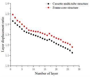
In the case of accidental eccentricity and -direction seismic action, the inter-layer displacement ratio and the layer displacement ratio of the high-rise cassette multi-tube structure and high-rise frame-core structure are linearly decreasing in general trend. However, a sharp point is appeared in the curve at the 17th floor, which is indicated that the displacement ratio of the 17th floor is became larger, that is caused by the smaller size of each component when the structural model is in the 17th floor. With the decrease of the number of layers, the inter-layer displacement ratio and layer displacement ratio is increased. The inter-layer displacement ratio of the cassette multi-tube structure is ranged from 1.055 to 1.426, and the layer displacement ratio is ranged from 1.125 to 1.430. And the inter-layer displacement ratio of the frame-core structure is ranged from 1.075 to 1.497, and the layer displacement ratio is ranged from 1.180 to 1.493. Both two structures are met the requirements of the code, and the inter-layer displacement ratio curve and layer displacement ratio curve of the frame-core structure are above the curves of the cassette multi-tube structure, which is indicated that the displacement ratio of the frame-core structure is greater than that of the cassette multi-tube structure, and the torsional effect of the cassette multi-tube structure is less than that of the frame-core structure under the -direction seismic action.
Fig. 10Inter-layer displacement ratio
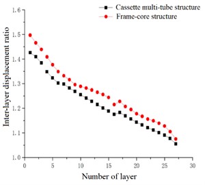
Fig. 11Layer displacement ratio
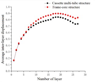
In the case of accidental eccentricity and -direction seismic action, the maximum inter-layer displacement and the average inter-layer displacement of the high-rise cassette multi-tube structure and high-rise frame-core structure are upward convex curves. The maximum inter-layer displacement of the cassette multi-tube structure is reached the maximum value at the 10th and 17th floors, which are 0.813 cm and 0.812 cm respectively, and the average inter-layer displacement is reached the maximum value at the 18th floor, which is 0.688 cm. The maximum and average inter-layer displacement of the frame-core structure is reached the maximum value at the 17th floor, which are 0.869 cm and 0.780 cm respectively. The maximum inter-layer displacement curve and average inter-layer displacement curve of the frame-core structure are above the curves of the cassette multi-tube structure, which is indicated that the maximum inter-layer displacement and the average inter-layer displacement of the frame-core structure is greater than that of the cassette multi-tube structure. According to the curves of maximum inter-layer displacement and the average inter-layer displacement, it can be seen that the minimum inter-layer displacement of frame-core structure is smaller than that of cassette multi-tube structure below the 7th floor, and that the minimum inter-layer displacement of frame-core structure is greater than that of cassette multi-tube structure above the 7th floor.
Fig. 12Maximum inter-layer displacement
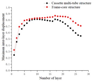
Fig. 13Average inter-layer displacement
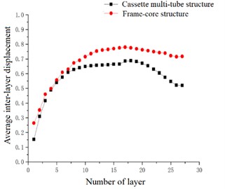
Fig. 14Maximum layer displacement
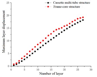
Fig. 15Average layer displacement
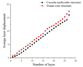
In the case of accidental eccentricity and -direction seismic action, the maximum layer displacement and the average layer displacement of the high-rise cassette multi-tube structure and high-rise frame-core structure are linearly increasing in general trend, and as the number of floors is increased, the displacement is increase. The layer displacement of each layer is superimposed by the inter-layer displacement of the layer and the below layers. At any layer, the layer displacement of the frame-core structure is greater than that of the cassette multi-tube structure, which is indicated that the lateral stiffness of the cassette multi-tube structure is better than that of the frame-core structure under the combined action of grid walls and grid hollow plates.
In the case of accidental eccentricity and -direction seismic action, the inter-layer displacement angle of the high-rise cassette multi-tube structure and high-rise frame-core structure are upward convex curves. The inter-layer displacement angle of the cassette multi-tube structure is reached the maximum value at the 10th and 17th floors, which are 2.624×10⁻⁴ and 2.619×10⁻⁴ respectively, the inter-layer displacement angle of the frame-core structure is reached the maximum value at the 17th floor, which is 2.987×10⁻⁴. The inter-layer displacement angle curve of the frame-core structure is only close to the curve of the cassette multi-tube structure below the 7th floor, while the distance between the inter-layer displacement angle curve of the two structures is increasing continuously above the 8th floor. which is indicated that the difference between the inter-layer displacement angle of the cassette multi-tube structure and the frame-core structure is very small at low floors, it is because of the frame-core structure is ensured strong stiffness by using large-sized components at the lower floors, which is resisted the earthquake action, so the inter-layer displacement angle of the frame-core structure is close to that of the cassette multi-tube structure. However, with the increase of the number of layers, the size of the frame-core structural components is constantly decreasing, and the stiffness is also decreasing. But the stiffness reduction of the cassette multi-tube structure is smaller than that of the frame-core structure due to the existence of grid walls and grid hollow plates, so the gap between the inter-layer displacement angle is constantly increasing.
Fig. 16Inter-layer displacement angle
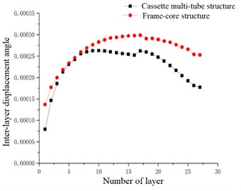
Fig. 17Inter-layer torsion angle
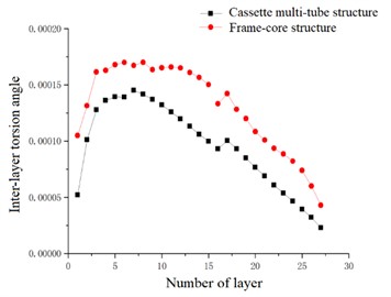
The inter-layer torsional angle is a more intuitive control index for the torsional performance of the structure. In the case of accidental eccentricity and -direction seismic action, the inter-layer torsion angle of the high-rise cassette multi-tube structure and high-rise frame-core structure are upward convex curves. The inter-layer torsion angle of the frame-core structure and the cassette multi-tube structure are reached the maximum value at the 7th floor, which are 452×10-4and 1.701×10⁻⁴ respectively. The torsional displacement angle of the frame-core structure at each layer is larger than that of the cassette multi-tube structure. It can be seen that the -direction torsional rigidity of the cassette multi-tube structure is greater than that of the frame-core structure, and the -direction torsional performance of the cassette multi-tube structure is better than that of the frame-core structure.
5.2. Seismic action of -direction
In the case of accidental eccentricity and -direction seismic action, the inter-layer displacement ratio and the layer displacement ratio of the high-rise cassette multi-tube structure and high-rise frame-core structure are linearly decreasing in general trend. The minimum value of inter-layer displacement ratio and the minimum value of layer displacement ratio in the -direction are smaller than those in the -direction. The inter-layer displacement ratio of the frame-core structure is ranged from 1.051 to 1.483, and the layer displacement ratio is ranged from 1.170 to 1.493. And the inter-layer displacement ratio of the cassette multi-tube structure is ranged from 1.016 to 1.435, and the layer displacement ratio is ranged from 1.106 to 1.432. In the displacement ratio curves of the two directions, the difference of layer displacement ratio between the cassette multi-tube structure and the frame-core structure in the -direction is larger than that between the two structures in the -direction. It is because of the grid walls of the cassette multi-tube structure are more distributed in the -direction, while the columns of the frame-core structure are not distributed enough in the -direction. So lateral stiffness of the two structures in the -direction is more different than that in the -direction.
Fig. 18Inter-layer displacement ratio
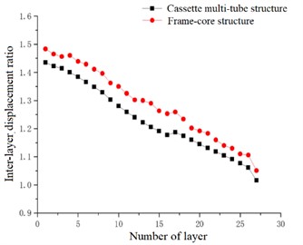
Fig. 19Layer displacement ratio
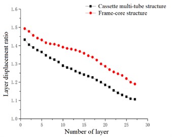
Fig. 20Maximum inter-layer displacement
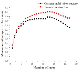
Fig. 21Average inter-layer displacement
In the case of accidental eccentricity and -direction seismic action, the maximum inter-layer displacement and the average inter-layer displacement of the high-rise cassette multi-tube structure and high-rise frame-core structure are upward convex curves. The slope of the inter-layer displacement curve in the -direction and the magnitude of increase of the inter-layer displacement value in the -direction are similar to that of the -direction in the 0-10 layers. However maximum inter-layer displacement curve -direction is tended to be gentle in the 10-16 layers, and the average inter-layer displacement curve is increased slightly in the 10-16 layers. The curve in the -direction is also reached maximum value at the 17th floor, but after the 17th floor, the magnitude of decrease of the inter-layer displacement value in the -direction is much smaller than that in the -direction. Therefore, it can be seen that the inter-layer displacement in the -direction is larger than that in the -direction. The maximum inter-layer displacement and the average inter-layer displacement of the cassette multi-tube structure are 0.986 cm and 0.840 cm respectively, and the maximum inter-layer displacement and the average inter-layer displacement of the frame-core structure are 1.104 cm and 0.897 cm respectively. The maximum inter-layer displacement curve and average inter-layer displacement curve of the frame-core structure are above the curves of the cassette multi-tube structure in the -direction, which is indicated that the lateral stiffness of the cassette multi-tube structure is better than that of the frame-core structure in the -direction.
In the case of accidental eccentricity and -direction seismic action, the maximum layer displacement and the average layer displacement of the high-rise cassette multi-tube structure and high-rise frame-core structure are linearly increasing in general trend. But the maximum value of the layer displacement curve in the -direction is greater than the maximum value the layer displacement curve in the -direction. The maximum values of maximum layer displacement and average layer displacement of the cassette multi-tube structure are 21.340 cm and 17.809 cm respectively, and the maximum values of maximum layer displacement and average layer displacement of the frame-core structure are 23.424 cm and 20.099 cm respectively. The maximum value of two structures in the -direction are greater than that in the -direction. Which is indicated that the lateral stiffness of two structures in the -direction is better than that in the -direction, and the lateral stiffness of the cassette multi-tube structure is also better than that of the frame-core structure in the -direction. The inter-layer displacement of the two structures is uniformly increased, it means that the structure is uniformly deformed, and the stiffness of the structure does not mutate in the vertical direction, that is met the requirements of the code.
Fig. 22Maximum layer displacement
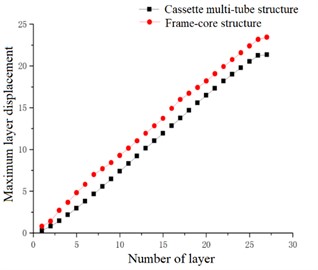
Fig. 23Average layer displacement
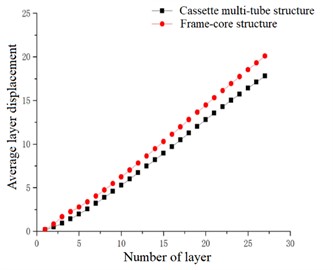
Fig. 24Inter-layer displacement angle
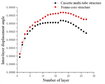
Fig. 25Inter-layer torsion angle
In the case of accidental eccentricity and -direction seismic action, the inter-layer displacement angle of the high-rise cassette multi-tube structure and high-rise frame-core structure are upward convex curves. The inter-layer displacement angle of the cassette multi-tube structure is reached the maximum value at the 17th floor, which is 3.182×10⁻⁴, and the inter-layer displacement angle of the frame-core structure is also reached the maximum value at the 17th floor, which is 3.679×10⁻⁴. The inter-layer displacement angle curve of the frame-core structure are above the curve of the cassette multi-tube structure. It can be seen that the inter-layer displacement angle of the two structures in the -direction is greater than the inter-layer displacement angle in the -direction, it is because of the length of the two structures in the -direction is greater than the length in the -direction, and part of the seismic force in the -direction is acted on the shear walls that is reduced the seismic force which is acted on the frame in the -direction, and the overall inter-layer displacement angle in the -direction is smaller than the inter-layer displacement angle in the -direction.
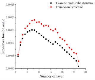
In the case of accidental eccentricity and -direction seismic action, the inter-layer torsion angle of the high-rise cassette multi-tube structure and high-rise frame-core structure are upward convex curves. The inter-layer torsion angles of the cassette multi-tube structure and the frame-core structure are reached the maximum value at the 7th floor, which are 1.506×10⁻⁴ and 1.898×10⁻⁴ respectively. The torsional displacement angle of the frame-core structure at each layer is also larger than that of the cassette multi-tube structure. It can be seen that the -direction torsional rigidity of the cassette multi-tube structure is greater than that of the frame-core structure, and the -direction torsional performance of the cassette multi-tube structure is better than that of the frame-core structure.
By comparing the -direction and -direction inter-layer torsion angles, it can be seen that The torsional angle of the cassette multi-tube structure in the direction is larger than that in the direction, and the difference between the two directions is small, and the maximum difference between the inter-layer torsion angle is only 3.72 %, which is indicated that the torsional properties of the cassette multi-tube structure are similar in the two directions, and the torsional stiffness distribution is relatively average. The torsional angle of the frame-core structure in the direction is larger than that in the direction, and the maximum difference is 11.58 %, which is indicated that the distribution of torsional stiffness in the direction is larger than that in the direction. Comparing the data in Table 5, the values corresponding to the frame-core structure are greater than those corresponding to the cassette multi-tube structure. It can be seen that the torsional rigidity of the cassette multi-tube structure is greater than that of the frame-core structure, and the torsional performance of the cassette multi-tube structure is better than that of the frame-core structure.
Table 5Comparison of key parameters between cassette multi-tube structure and frame-core structure
-direction | -direction | |||
Cassette multi-tube structure | Frame-core structure | Cassette multi-tube structure | Frame-core structure | |
Inter-layer displacement ratio | 1.426 | 1.497 | 1.435 | 1.483 |
Layer displacement ratio | 1.43 | 1.493 | 1.432 | 1.493 |
Maximum inter-layer displacement | 0.813 cm | 0.869 cm | 0.986 cm | 1.104 cm |
Average inter-layer displacement | 0.688 cm | 0.78 cm | 0.84 cm | 0.897 cm |
Maximum layer displacement | 18.141 cm | 19.224 cm | 21.34 cm | 23.424 cm |
Average layer displacement | 15.985 cm | 17.357 cm | 17.809 cm | 20.099 cm |
Inter-layer displacement angle | 2.624×10⁻⁴ | 2.987×10⁻⁴ | 3.182×10⁻⁴ | 3.679×10⁻⁴ |
Inter-layer torsion angle | 1.452×10⁻⁴ | 1.701×10⁻⁴ | 1.506×10⁻⁴ | 1.898×10⁻⁴ |
6. Evaluation and summary
The above analysis is showed that the actual torsional effect of the bottom layer of the cassette multi-tube structure is relatively small, but the maximum (average) inter-layer displacement, inter-layer displacement angle and inter-layer torsion angle of the 7th-10th layer of the cassette multi-tube structure are all in the larger value or maximum value. Which is indicated that although the inter-layer displacement ratio and the layer displacement ratio of the 7th-10th layer are smaller than that of the bottom layer. But in fact, the torsional effect is the greatest in 7th-10th layers. Why does the displacement ratio cannot be reflected the actual torsional effect of the structure? It is because of the displacement ratio is a relative index, when the maximum displacement inter-layer (layer) and the average displacement inter-layer (layer) of a certain layer of the structure are very small, the average displacement inter-layer (layer) is approached to zero faster than the maximum displacement inter-layer (layer), then the displacement ratio may be large and which is exceeding the limit value required by the code.
In the elastic stage, the inter-layer torsion angle is represented the torsion effect of the cassette multi-tube structure. The torsion effect of the cassette multi-tube structure is smaller when the inter-layer torsion angle is more and more small, and the torsion effect of the cassette multi-tube structure is larger when the inter-layer torsion angle is more and more large. When the maximum displacement of the inter-layer layer is met the requirements of the code, the torsion of the cassette multi-tube structure can be controlled by the change of the inter-layer torsion angle is limited. And the inter-layer torsion angle is an absolute index, and the inter-layer torsion angle will not be changed because of other conditions of the structure. So inter-layer torsion angle can be used as an index to control the torsion of the cassette multi-tube structure.
The maximum torsion of the two structures is occurred at the 7th layer, which is different from the conclusion that the torsion of the bottom layer is the maximum which is obtained from the inter-layer displacement ratio and the inter-layer displacement ratio. It can be seen from the curves of the maximum inter-layer displacement, the average inter-layer displacement and the inter-layer displacement angle that the structure is a large value at the 7th layer. Which is also proved the accuracy of the inter-layer torsion angle. The displacement ratio as a torsional control index is needed further research and optimization.
7. Conclusions
In this article, the applicability of the software is analyzed for the cassette multi-tube structure and the frame-core structure, then the torsion effect of the two structures is compared and analyzed, and the torsion control index of the structure is studied and the following conclusions can be drawn.
1) By comparing the period and structure quality of the two structural models in “PKPM” software and “MIDAS-Gen” software, it can be seen that the period error and quality error of the structural models in the two software are less than 5 %, and the cassette multi-tube structure and the frame-core tube structure are more accurate in the “MIDAS-Gen” software.
2) The “Code for Seismic Design of Buildings” does not stipulate that the influence of accidental eccentricity should be considered, while the “Technical Specification for Concrete Structures of Tall Buildings” is only stipulated that the influence of accidental eccentricity should be considered when unidirectional seismic action is calculated. But accidental eccentricity is an actual factor that cannot be ignore, therefore the influence of accidental eccentricity should be considered. As for the torsion cycle ratio, there are some unreasonable points in the code, which is easy to cause designers to misunderstand the code and is made big mistakes in the design, so it is urgent to find a new control index to control the structural torsion.
3) The difference in the displacement angle between the layers of the cassette multi-tube structure and the frame-core structure is very small at the lower level, it is because of the frame-core structure can be ensured strong stiffness at the lower level through large-sized components, thus resisting the earthquake action. However, with the increase of the number of layers, the size of the frame-core structural components is constantly decreasing, and its stiffness is also decreasing. However, the degree of stiffness reduction of cassette multi-tube structure is smaller than that of the frame-core structure due to the presence of grid walls and grid shaped hollow plates, so the difference of displacement angle between layers of two structures is increasing.
4) By comparing the -direction and -direction inter-layer torsion angles, it can be seen that The torsional angle of the cassette multi-tube structure in the direction is larger than that in the direction, and the difference between the two directions is small, and the maximum difference between the inter-layer torsion angle is only 3.72 %, which is indicated that the torsional properties of the cassette multi-tube structure are similar in the two directions, and the torsional stiffness distribution is relatively average. The torsional angle of the frame-core structure in the direction is larger than that in the direction, and the maximum difference is 11.58 %, which is indicated that the distribution of torsional stiffness in the direction is larger than that in the direction.
5) The maximum torsion of the two structures is occurred at the 7th layer, which is different from the conclusion that the torsion of the bottom layer is the maximum which is obtained from the inter-layer displacement ratio and the layer displacement ratio. It can be seen from the curves of the maximum inter-layer displacement, the average inter-layer displacement and the inter-layer displacement angle that the larger value at the 7th layer. This also proved the accuracy of the inter-layer torsion angle. The inter-layer displacement ratio and the layer displacement ratio as a torsional control index is needed further research and optimization.
6) By comparing the torsional effect of cassette multi-tube structure with that of frame-core structure, the control index of torsional effect of cassette multi-tube structure is smaller than that of frame-core structure, which is indicated that the torsional performance of cassette multi-tube structure is better than that of frame-core structure. In addition, the torsional performance of the cassette multi-tube structure is obviously better than that of the frame-core structure with the increase of the number of floors.
7) The limits of mechanical properties such as period ratio, displacement ratio and displacement angle considered in the analysis of mechanical properties of the cassette multi-tube structure in this article are not clearly specified in the code, and all based on the limits of the frame-core structure in the code, which is not reasonable, and further research is needed to determine the limits of various mechanical properties of the cassette multi-tube structure.
References
-
P. F. Xu, Structural Design of Complex High-Rise Buildings. (in Chinese), China Architecture & Building Press, 2005.
-
H. Varaee, A. Shishegaran, and M. R. Ghasemi, “The life-cycle cost analysis based on probabilistic optimization using a novel algorithm,” Journal of Building Engineering, Vol. 43, p. 103032, Nov. 2021, https://doi.org/10.1016/j.jobe.2021.103032
-
M. S. Es-Haghi, A. Shishegaran, and T. Rabczuk, “Evaluation of a novel asymmetric genetic algorithm to optimize the structural design of 3d regular and irregular steel frames,” Frontiers of Structural and Civil Engineering, Vol. 14, No. 5, pp. 1110–1130, Sep. 2020, https://doi.org/10.1007/s11709-020-0643-2
-
A. Shishegaran, M. R. Ghasemi, and H. Varaee, “Performance of a novel bent-up bars system not interacting with concrete,” Frontiers of Structural and Civil Engineering, Vol. 13, No. 6, pp. 1301–1315, Oct. 2019, https://doi.org/10.1007/s11709-019-0552-4
-
A. Shishegaran, B. Karami, T. Rabczuk, A. Shishegaran, M. A. Naghsh, and M. Mohammad Khani, “Performance of fixed beam without interacting bars,” Frontiers of Structural and Civil Engineering, Vol. 14, No. 5, pp. 1180–1195, Oct. 2020, https://doi.org/10.1007/s11709-020-0661-0
-
M. Fahiminia and A. Shishegaran, “Evaluation of a developed bypass viscous damper performance,” Frontiers of Structural and Civil Engineering, Vol. 14, No. 3, pp. 773–791, Jun. 2020, https://doi.org/10.1007/s11709-020-0627-2
-
A. Shishegaran, M. R. Khalili, B. Karami, T. Rabczuk, and A. Shishegaran, “Computational predictions for estimating the maximum deflection of reinforced concrete panels subjected to the blast load,” International Journal of Impact Engineering, Vol. 139, p. 103527, May 2020, https://doi.org/10.1016/j.ijimpeng.2020.103527
-
C. Pany, S. Parthan, and S. Mukherjee, “Vibration analysis of multi-supported curved panel using the periodic structure approach,” International Journal of Mechanical Sciences, Vol. 44, No. 2, pp. 269–285, Feb. 2002, https://doi.org/10.1016/s0020-7403(01)00099-6
-
C. Pany and S. Parthan, “Flutter analysis of periodically supported curved panels,” Journal of Sound and Vibration, Vol. 267, No. 2, pp. 267–278, Oct. 2003, https://doi.org/10.1016/s0022-460x(02)01493-1
-
C. Pany and S. Parthan, “Axial wave propagation in infinitely long periodic curved panels,” Journal of Vibration and Acoustics, Vol. 125, No. 1, pp. 24–30, Jan. 2003, https://doi.org/10.1115/1.1526510
-
C. Pany, “An insight on the estimation of wave propagation constants in an orthogonal grid of a simple line-supported periodic plate using a finite element mathematical model,” Frontiers in Mechanical Engineering, Vol. 8, Jul. 2022, https://doi.org/10.3389/fmech.2022.926559
-
Y. T. Zhang, “Seismic analysis of irregularly arranged frame structures,” (in Chinese), Dalian University of Technology, 2020.
-
Z. Liu, X. Wang, Z. Zhou, J. Xue, B. Lai, and J. Xu, “Experimental and numerical study on seismic performance of steel reinforced concrete spatial frame with irregular section columns,” Engineering Structures, Vol. 242, p. 112507, Sep. 2021, https://doi.org/10.1016/j.engstruct.2021.112507
-
E. D. Wolff, C. Ipek, M. C. Constantinou, and L. Morillas, “Torsional response of seismically isolated structures revisited,” Engineering Structures, Vol. 59, pp. 462–468, Feb. 2014, https://doi.org/10.1016/j.engstruct.2013.11.017
-
C. G. Karayannis and M. C. Naoum, “Torsional behavior of multistory RC frame structures due to asymmetric seismic interaction,” Engineering Structures, Vol. 163, pp. 93–111, May 2018, https://doi.org/10.1016/j.engstruct.2018.02.038
-
H. Mao, X. Yan, X. Wei, and X. Liu, “Seismic analysis of a frame structure equipped with displacement-amplified torsional dampers,” Structures, Vol. 41, pp. 190–202, Jul. 2022, https://doi.org/10.1016/j.istruc.2022.05.003
-
Y. L. Rutman, E. Simbort, and D. E. Bondarev, “An analysis of the dynamics of seismically isolated structures taking into account its torsional vibrations,” Procedia Structural Integrity, Vol. 6, pp. 208–215, Jan. 2017, https://doi.org/10.1016/j.prostr.2017.11.032
-
K. J. Ma, G. F. Gao, and H. G. Zhang, “Feasibility study report on comprehensive application of phosphogypsum in residential buildings with flexible division of bedrooms in large rooms,” (in Chinese), Space Structures Research Center, Guizhou University, Guizhou, 2007.
-
K. J. Ma et al., “Experimental study on new type reinforced concrete structural system with phosphor gypsum as a template,” (in Chinese), Journal of Building Structures, Vol. 30, pp. 128–133, 2009, https://doi.org/10.14006/j.jzjgxb.2009.06.017
-
K. J. Ma, “Construction of energy-saving residential building with large opening of Shiqing wall with steel structure and production method of field stratification and segmentation,” (in Chinese), Chinese patent: CN101691784A, 2010.
-
Q. W. Xiong et al., “Performance analysis of RC space grid cassette multi-tube structure system,” (in Chinese), Journal of Guizhou University (Natural Science), Vol. 31, pp. 71–76, 2014, https://doi.org/10.15958/j.cnki.gdxbzrb.2014.05.018
-
Z. H. Tan, K. J. Ma, and Y. Liang, “Research and application of assembled monolithic space steel grid box structure in high-rise residential building,” (in Chinese), Journal of Guizhou University (Natural Science), Vol. 29, pp. 126–130, 2012, https://doi.org/10.15958/j.cnki.gdxbzrb.2012.06.020
-
H. G. Zhang, K. J. Ma, and Y. Q. Lu, “Ribbed frame structure applying phosphogyp sum form work of small high-rise building,” (in Chinese), Journal of Guizhou University of Technology (Natural Science Edition), Vol. 37, pp. 28–32, 2008.
-
“Code for seismic design of buildings,” China Architecture and Building Press, Beijing, GB50011-2010, 2010.
-
“Technical specification for concrete structures in high-rise buildings,” (in Chinese), China Architecture & Building Press, Beijing, JGJ3-2010, 2010.
-
X. B. Zhang et al., “Pushover analysis for the seismic performance of the high-rise RC space grid cassette multi-tube structure system,” (in Chinese), Journal of Safety and Environment, Vol. 21, pp. 1455–1466, 2021, https://doi.org/10.13637/j.issn.1009-6094.2020.0047
-
Q. M. Wang et al., “Experimental study of gypsum-case embedded RC dense rib cavity slab floor,” (in Chinese), Spatial Structures, Vol. 18, pp. 3–7, 2012, https://doi.org/10.13849/j.issn.1006-6578.2012.03.003
-
J. Han, “Comparative analysis of torsional control and design methods of seismic structures at home and abroad,” (in Chinese), Journal of Xi’an University of Architecture and Technology, Vol. 40, pp. 25–32, 2008.
-
L. Zuo, “Analysis of torsion effect of concrete frame-core tube structure,” (in Chinese), Hunan University, Hunan, 2017.
About this article

The authors have not disclosed any funding.
The datasets generated during and/or analyzed during the current study are available from the corresponding author on reasonable request.
Jiang An-Min wrote the paper. Zhang Futian, Xiong Qi-Wei, Wang Fei-Fei and Dong Yan-Chen carried out the analog computation.
The authors declare that they have no conflict of interest.
