Abstract
Automobile-robot (self-driving automobile) is being researched and developed vigorously. When the automobile-robot is moving on the road surface, the low frequency vibration excitation not only influences the ride comfort of the automobile-robot but also strongly affects the durability of the vehicle’s structures. To research the automobile-robot’s vibration in the low frequency region, a dynamic model of the vehicle is established to calculate the vibration equations in the time region. Based on the theory of the Laplace transfer function, the automobile-robot’s vibration equations in the time region are transformed and converted to the vibration equations in the frequency region. Then, the effect of the design parameters and operation parameters on the characteristic of the automobile-robot’s acceleration-frequency is simulated and analyzed to evaluate the ride comfort as well as the durability of the automobile-robot’s structures in the frequency region. The research results show that the design parameters of the stiffness, mass, and road wavelength remarkably affect the characteristic of the automobile-robot’s acceleration-frequency. To reduce the resonant amplitude of the acceleration-frequency in the vertical and pitching direction of the automobile-robot, the stiffness parameters of the automobile-robot's and tires should be reduced while the mass of the automobile-robot’s body should be increased. Additionally, the road’s roughness also needs to be decreased or the road’s quality needs to be enhanced to reduce the resonant amplitude of the automobile-robot’s acceleration-frequency.
1. Introduction
To increase driver comfort, vehicle manufacturers are developing self-driving car systems, also known as automobile-robot. The vibration isolation structure of automobile-robot is similar to the vibration isolation structure of the traditional automobile. The isolation systems of the automobile-robot have been used to reduce the vibration excitations from the road surface transmitted to the automobile-robot’s body. In the design process of the vehicle’s suspension systems, the structures of the suspension system were designed by the spring and damper with the stiffness parameter and damping parameter. The study showed that these parameters greatly affected the ride comfort of the vehicle [1]. In order to enhance the ride comfort of the vehicle or automobile, these design parameters were optimized by the genetic algorithm [2-3]. By searching for the best stiffness and damping parameters for the automobile’s suspension systems, the automobile’s ride comfort has been improved in comparison with the passive suspension systems. However, the automobile’s ride comfort was still low under the high speeds of the automobile’s moving or the automobile’s moving on the poor road surface roughness. Therefore, the automobile’s suspension systems were improved by using the control damping forces of semi-active suspension systems [4-5] or semi-active air suspension systems [6]. The research results showed that with the control damping forces of the semi-active suspension systems used, the automobile’s ride comfort was better than that of the automobile’s optimal suspension systems under different operation conditions. However, the research also indicated that the control performance of the semi-active suspension systems strongly depended on the control method and control rule of the algorithm programs [7-8]. To enhance the control performance, advanced control methods using the Adaboost algorithm and machine learning were applied [9-10]. In the above studies, the dynamic model was established to calculate the vibration equations of the automobile. Then, these vibration equations were built and simulated to compute the automobile’s acceleration responses in the time region. The root mean square values of these acceleration responses were then computed to assess the automobile’s ride comfort based on ISO 2631-1:1997 [11].
However, ISO 2631-1 showed that the ride comfort and health of the driver were also strongly affected by the vehicle’s vibration excitations in the frequency region [11], especially at the excitations in the low frequency from 0.5 to 10 Hz of the road surface when the vehicle is moving. From the random excitations of the road surface built based on ISO 8068 [12], the interaction models of the vehicle and random road surface were established and studied the vibration of the vehicle or cab in the low frequency region [13-14]. Besides, the effect of the design parameters of the isolation systems on the vehicle’s vibrations in the low frequencies was also evaluated [15-16]. The results indicated that the density of resonant frequencies and resonant amplitudes of automobile-robot’s acceleration-frequency response appeared very much in the low frequency region, especially at excitations from 0.5 to 4.0 Hz. This not only affected the driver’s health but also strongly affected the durability of the automobile-robot’s structures and road surfaces. Thus, the resonant frequencies and resonant amplitudes in the automobile-robot’s acceleration-frequency response in this excitation range needed to be minimized. These resonant frequencies and resonant amplitudes were directly impacted by the design parameters and operation parameters of the automobile-robots such as the stiffness, mass, speed, and road surface, etc. Therefore, the effect of the design parameters and operation parameters of the automobile-robots on the driver’s health and the durability in automobile-robot’s structures under different frequency excitations need to be researched and analyzed. However, this issue has not been considered in the existing research.
In this study, a dynamic model of the automobile-robot is established to calculate its vibration equations in the time region. Based on the theory of the Laplace transfer function [17], the automobile-robot’s vibration equations in the time region are transformed and converted to the automobile-robot’s vibration equations in the frequency region. Then, the effect of the automobile-robot’s design parameters and operation parameters on the characteristic of the automobile-robot’s acceleration-frequency is simulated and analyzed to evaluate the automobile-robot’s ride comfort as well as the durability of the automobile-robot’s structures in the frequency region. Enhancing the working performance of the automobile-robot is the goal of this study.
2. Automobile-robot’s mathematical model
2.1. Calculating the vibration equations of the automobile-robot in the time region
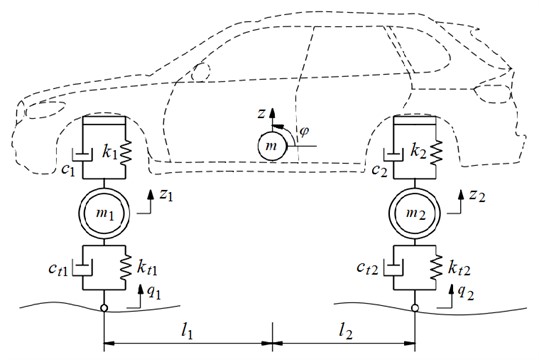
In order to compute an automobile-robot’s vibration equations, based on its actual structure, a 2-D automobile-robot dynamics model is established and shown in Fig. 1, where four degrees of freedom of the automobile-robot including the automobile-robot body’s vertical vibration, automobile-robot’s pitch vibration, front axle’s vibration, and rear axle’s vibration are defined by z, φ, z1, and z2, respectively. The mass of the automobile-robot’s body, front-axle, and rear-axle are also defined by m, m1, and m2, respectively. The stiffness and damping parameters of the front and rear axles are also defined by {c1 and k1} and {c2 and k2}. The stiffness and damping parameters of front and rear tires are also defined by {ct1 and kt1} and {ct2 and kt2}. l1,2 and q1,2 are the distances and vibration excitations of the automobile-robot and tires.
From the automobile-robot’s dynamics model shown in Fig. 1, its vibration equations are then written by:
Fig. 1The dynamic model of the automobile-robot
In the research of the automobile-robot’s vibration, the automobile-robot’s vibration in the time region is mainly applied for assessing the automobile-robot’s comfort. However, based on ISO 2631-1:1997 [11], the automobile-robot’s vibration responses in the frequency region also greatly affected the ride comfort and structure in the automobile-robot’s systems. Therefore, in this study, the vibration characteristic of the automobile-robot in the frequency region will be researched and evaluated under different operation conditions of the automobile-robot.
2.2. Calculating the vibration equations of the automobile-robot in the frequency range
To establish the automobile-robot’s vibration equations in the frequency region as well as evaluate the vibration characteristic of the car in the frequency region, based on the automobile-robot’s vibration equation in the time region in Eq. (1), the Laplace transfer function [17] is then used to convert Eq. (1) in the time region (t) to the image function (s) in the frequency region with the excitation frequency of ω. Herein, ω=2πf and s=d/dt.
The theory of the Laplace transfer function is described by: If a vibration function of n(t) operates and depends on the variable time of t>0 in its operation range defined by {a and b}, based on the method of the Laplace transfer function, the image function of n(t) defined by N(s) is expressed as follows:
Or:
Similarly, based on the theory of the Laplace transfer function, the derivative equations of the image function of n(t), ˙n(t), and ¨n(t) are also written by [17]:
From the dynamic model of the car in Fig. 1, at the initial condition of the automobile-robot moving when t=0, the vibration responses of the automobile-robot’s and front/rear wheel axles are equal to zero (z(t)=0, φ(t)=0, z1(t)=0, and z2(t)=0). Therefore, the derivative equations of their image function at the initial condition when t=0 are also equal to zero (N(0)=0).
Based on the Laplace transfer function in Eqs. (3) and (4), the derivative equations of the automobile-robot body’s vertical vibrationz(t), automobile-robot body’s pitch vibration φ(t), front axle’s vibration z1(t), and rear axle’s vibration z2(t) calculated in Eq. (1) at the time region are described by the image functions (s) of Z(s), Ψ(s), Z1(s), and Z2(s) in the frequency region as follows:
Thus, the automobile-robot’s vibration equation of Eq. (1) in the time region is rewritten by the automobile-robot’s vibration equation at the frequency range via the theory of Laplace functions as follows:
or:
By dividing Eq. (6) by Q1(s), the matrix of Eq. (6) has been rewritten by:
where s=iω,s2=-ω2,a11=-mω2+(k1+k2)+i(c1+c2)ω,a12=a21=(k1l1+k2l2)+i(c1l1+c2l2)ω, a31=a13=-k1-ic1ω, a41=a14=-k2-ic2ω, a22=-Iω2+(k1l1l1+k2l2l2)+i(c1l1l1+c2l2l2)ω, a32=a23=-k1l1-ic1l1ω, a42=a24=-k2l2-ic2l2ω,a33=-m1ω2+(k1+kt1)+i(c1+ct1)ω,a34=-m2ω2+(k2+kt2)+i(c2+ct2)ω, b3=kt1+ict1ω, and b4=kt2+ict2ω, respectively.
Let Tz=Z(s)/Q1(s), Tφ=Ψ(s)/Q1(s), Tz1=Z1(s)/Q1(s), and Tz2=Z2(s)/Q2(s), thus, Tz, Tφ, Tz1, and Tz2 are defined as the vibration’s transfer functions from the road to the automobile-robot body and front/rear axles, respectively.
Based on the calculated results in Refs [17], the result of the acceleration amplitude obtained via Tn= {Tz, Tφ, Tz1, and Tz2} in Eq. (7) under road’s excitations Q1(s) are written as follows:
2.3. Road’s excitations on car’s wheels
When the automobile-robot is traveling on the road, the vibration excitation of the road described by the harmonic function with its wavelength from 5 m to 10 m and its height from 0.01 m to 0.012 m greatly affects the automobile-robot’s ride comfort and structure [12, 18-19]. This harmonic function mainly causes resonant vibrations in the automobile-robot’s suspension system. Thus, this excitation is used to evaluate the vibration characteristic of the automobile-robot at the frequency range. The road surface’s vibration equation using the harmonic surface at time region has been described as:
With the frequency and wavelength of the road defined by L and l, Eq. (9) is then rewritten in the traveling direction of X as follows:
With an unchanged speed of the automobile-robot (v), thus, X=vt. Both Eqs. (9) and (10) are then rewritten by:
The basic length of the automobile-robot is defined by (l1+l2), as shown in Fig. 1, thus, the vibration excitation at the rear tire (q2) calculated based on the vibration excitation at the front tire is expressed by:
From the ratio of q2/q calculated based on Eqs. (11) and (12), the Laplace transformation Tq of q2/q1 is then described by:
Eq. (13) is then used as the vibration excitation of the automobile-robot to evaluate the characteristic of the automobile-robot’s vibrations in the frequency region.
3. Simulation and analysis result
Based on the automobile-robot’s excitations using the road’s harmonic function with q0=10 mm and the road’s wavelength l=8 m as well as the dynamic parameters of the automobile-robot listed in Table 1, the vibration characteristic of the automobile-robot in the frequency region under the different operation conditions is then simulated and analyzed.
Table 1Automobile-robot’s dynamic parameters
Parameters | Values | Parameters | Values | Parameters | Values |
m (kg) | 1384 | k1 (N/m) | 90880 | c1 (Ns/m) | 7733 |
m1(kg) | 66 | k2 (N/m) | 93884 | c2 (Ns/m) | 9804 |
m2 (kg) | 87 | kt1(N/m) | 193211 | ct1 (Ns/m) | 2000 |
I (kg.m2) | 11632 | kt2(N/m) | 226422 | ct2 (Ns/m) | 2000 |
l1 (m) | 1.35 | l2 (m) | 1.604 | q0 (mm) | 10 |
3.1. Automobile’s vibration characteristic under different stiffness of the suspension system
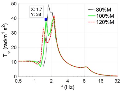
To evaluate the effect of stiffness parameters in the automobile-robot’s systems on the characteristic of the acceleration-frequency in the automobile-robot, three different stiffness parameters of the automobile-robot’s suspension system including K=[80%,100%,120%]×{k1,2,kt1,2} are simulated when the automobile-robot is traveling on the road surface with the harmonic function of q0= 10 mm and wavelength l= 8 m at v= 20 m/s. Results in the acceleration-frequency of the automobile-robot’s body in the vertical and pitching vibrations have been shown in Figs. 2(a) and 2(b).
Fig. 2The response of the automobile-robot body’s acceleration-frequency under different stiffness values
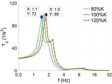
a) The vertical acceleration-frequency
b) The pitching acceleration-frequency
The simulation results show that both the responses of the acceleration-frequency of the automobile-robot’s body in the vertical and pitching directions are significantly affected by the different stiffness coefficients of the automobile-robot’s suspensions and wheels. Resonant frequencies in the vertical and pitching direction of the automobile-robot in the low frequency region appeared at 1.1 Hz, 1.3 Hz, and 1.5 Hz when the stiffness parameters were reduced by 80 %K, used by 100 %K, and increased by 120 %K, respectively. Additionally, the acceleration-frequency amplitude in the vertical and pitching direction of the automobile-robot at low frequencies is also depended on stiffness coefficients in the automobile-robot’s suspension systems and wheels. The automobile-robot’s acceleration-frequency amplitudes are increased with the increase of the stiffness parameters and vice versa. These results mean that the K of the automobile-robot’s suspensions and wheels not only influences the amplitude but also influences the resonant-frequency of the automobile-robot’s acceleration frequency in both the vertical and pitching direction. In order to ameliorate the automobile-robot’s comfort as well as ensure the durability in automobile-robot’s structures, the designed parameters in the stiffness of automobile-robot’s suspensions and tires need to be chosen to minimum the amplitude of automobile-robot’s acceleration frequency at resonant frequencies.
3.2. Automobile’s vibration characteristic under different mass
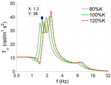
The analysis results in Section 3.1 show that the automobile-robot’s acceleration-frequency amplitudes and resonant frequencies are affected by the stiffness parameters of the automobile-robot. Besides, based on the formula used to determine the resonant frequency of the system, the resonant frequency is calculated by f2=K/M. Thus, the automobile-robot’s mass (M) is also influenced the automobile-robot’s acceleration-frequency characteristic. To clearly this issue, the automobile-robot’s different mass including M=[80%,100%,120%]×{m,m1,m2} are also simulated under the same excitation of the road surface in Section 3.1. The results of the acceleration-frequency of the automobile-robot’s body in the vertical and pitching vibrations are plotted in Figs. 3(a) and 3(b).
The simulation results indicate that both the responses of the acceleration-frequency of the automobile-robot’s body in the vertical and pitching directions are also significantly affected by the different mass in automobile-robot’s body and front/rear-axles. The resonant frequencies in the vertical and pitching direction of the automobile-robot in the low frequency region are appeared at 1.5 Hz, 1.7 Hz, and 1.9 Hz when the automobile-robot’s mass is increased by 120 %M, used by 100 %M, and reduced by 80 %M, respectively.
Fig. 3The response of the automobile-robot body’s acceleration-frequency under different load conditions
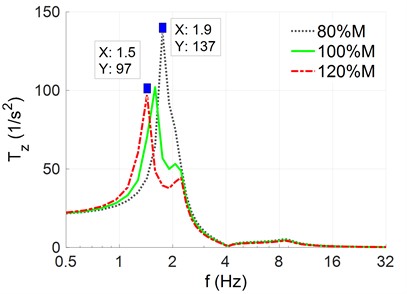
a) The vertical acceleration-frequency
b) The pitching acceleration-frequency
Besides, the amplitude of the acceleration-frequency in the vertical and pitching direction of the automobile-robot in the low frequency region is also dependent on the automobile-robot’s mass. The automobile-robot’s acceleration-frequency amplitudes are increased when the automobile-robot’s mass is reduced and vice versa. This also means that the automobile-robot’s mass not only influences amplitudes but also influence resonant-frequencies of automobile-robot’s acceleration frequency in both the vertical and pitching direction. In order to ameliorate automobile-robot’s comfort and ensure durability in automobile-robot’s structures, in the design process of the automobile-robot, both the mass M and stiffness K of the automobile-robot’s systems should be calculated and chosen to minimize the amplitude of the acceleration-frequency at the resonant frequencies.
3.3. Automobile’s vibration characteristic under road’s different wavelengths
In the automobile-robot’s condition traveling on the pavement, the road wavelength can affect the automobile-robot’s ride comfort. To clear this issue, three different wavelengths of the road including l=6 m, l=8 m, and l=10 m at the same excitations of the road in Section 3.1 are simulated, respectively. The results of the acceleration-frequency of the automobile-robot’s body in the vertical and pitching vibrations are plotted in Figs. 4(a) and 4(b).
Fig. 4The response of the automobile-robot body’s acceleration-frequency under road’s different wavelengths
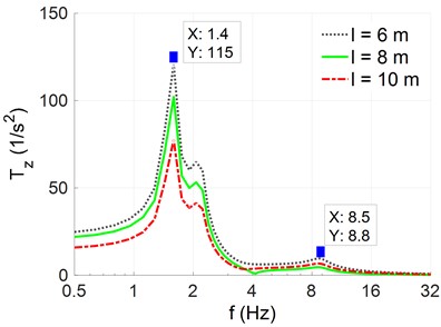
a) The vertical acceleration-frequency
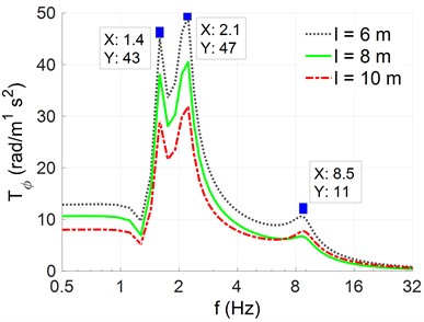
b) The pitching acceleration-frequency
The simulation results in both Figs. 4(a) and 4(b) show that the resonant frequencies of the automobile-robot’s body in the vertical and pitching vibrations un-change and appear at 1.4 Hz, 2.1 Hz, and 8.5 Hz under the different values of the road wavelength. This means that the road wavelength not influences characteristics of the automobile-robot’s acceleration frequency. However, the amplitude of the acceleration-frequency in the vertical and pitching direction of the automobile-robot in the low frequency region is changed and affected by the road’s different wavelengths. Their amplitude is increased when the road’s wavelength is reduced and vice versa. Thus, to reduce the amplitude of the acceleration-frequency in the vertical and pitching direction of the automobile-robot, the road’s wavelength needs to be increased. This means that the pavement’s roughness needs to be decreased or the pavement’s surface quality needs to be enhanced. This issue is also proven and recommended in existing studies [20].
4. Conclusions
With automobile-robot (autonomous driving car), investigating frequency response to evaluate ride comfort and structural safety is a necessary issue. This study uses the complex-domain method for evaluating automobile-robot’s vibrations in the frequency region. The study can be summarized as follows:
The design parameters of the stiffness, mass, and road wavelength remarkably affect to characteristics of the automobile-robot’s acceleration frequency.
To reduce resonant amplitudes of the automobile-robot’s acceleration frequency in both vertical and pitching directions, stiffness parameters in the automobile-robot’s suspensions and tires should be reduced while the mass of the automobile-robot’s body should be increased. However, the reduction of the stiffness of the automobile-robot can lead to reduce the stability and safety of movement of the automobile-robot. To solve this issue, the automobile-robot’s suspension systems are researched and replaced by using air suspension systems or active suspension systems.
The resonant amplitude of the acceleration-frequency in the vertical and pitching direction of the automobile-robot is significantly affected by the road wavelength, thus, to reduce this resonant amplitude, the pavement’s roughness needs to be decreased or the pavement’s surface quality needs to be enhanced.
References
-
Y. Yang, W. Ren, L. Chen, M. Jiang, and Y. Yang, “Study on ride comfort of tractor with tandem suspension based on multi-body system dynamics,” Applied Mathematical Modelling, Vol. 33, No. 1, pp. 11–33, Jan. 2009, https://doi.org/10.1016/j.apm.2007.10.011
-
N. Nariman-Zadeh, M. Salehpour, A. Jamali, and E. Haghgoo, “Pareto optimization of a five-degree of freedom vehicle vibration model using a multi-objective uniform-diversity genetic algorithm (MUGA),” Engineering Applications of Artificial Intelligence, Vol. 23, No. 4, pp. 543–551, Jun. 2010, https://doi.org/10.1016/j.engappai.2009.08.008
-
R. Pekgökgöz, M. Gurel, M. Bilgehan, and M. Kisa, “Active suspension of cars using fuzzy logic controller optimized by genetic algorithm,” International of Journal Engineering Application Sciences, Vol. 2, No. 4, p. 27, Jul. 2010.
-
M. Ghoniem, T. Awad, and O. Mokhiamar, “Control of a new low-cost semi-active vehicle suspension system using artificial neural networks,” Alexandria Engineering Journal, Vol. 59, No. 5, pp. 4013–4025, Oct. 2020, https://doi.org/10.1016/j.aej.2020.07.007
-
Y. Zhu, X. Bian, L. Su, C. Gu, Z. Wang, and C. Shi, “Ride comfort improvement with preview control semi-active suspension system based on supervised deep learning,” SAE International Journal of Vehicle Dynamics, Stability, and NVH, Vol. 5, No. 1, p. 31, Jan. 2021, https://doi.org/10.4271/10-05-01-0003
-
H. Wang, P. Kin Wong, J. Zhao, Z.-X. Yang, and Z.-X. Yang, “Observer-based robust gain-scheduled control for semi-active air suspension systems subject to uncertainties and external disturbance,” Mechanical Systems and Signal Processing, Vol. 173, p. 109045, Jul. 2022, https://doi.org/10.1016/j.ymssp.2022.109045
-
L. C. Félix-Herrán, D. Mehdi, J. J. Rodríguez-Ortiz, R. Soto, and R. Ramírez-Mendoza, “Hinf control of a suspension with a magnetorheological damper,” International Journal of Control, Vol. 85, No. 8, pp. 1026–1038, Aug. 2012, https://doi.org/10.1080/00207179.2012.674216
-
I. Maciejewski, “Control system design of active seat suspensions,” Journal of Sound and Vibration, Vol. 331, No. 6, pp. 1291–1309, Mar. 2012, https://doi.org/10.1016/j.jsv.2011.11.010
-
L. Wang, J. Li, Y. Yang, J. Wang, and J. Yuan, “Active control of low-frequency vibrations in ultra-precision machining with blended infinite and zero stiffness,” International Journal of Machine Tools and Manufacture, Vol. 139, pp. 64–74, Apr. 2019, https://doi.org/10.1016/j.ijmachtools.2018.11.004
-
Z. Tianjun et al., “Model reference adaptive control of semi-active suspension model based on adaboost algorithm for rollover prediction,” SAE International Journal of Vehicle Dynamics, Stability, and NVH, Vol. 6, No. 1, pp. 71–86, Nov. 2021, https://doi.org/10.4271/10-06-01-0005
-
“Mechanical vibration and shock-evaluation of human exposure to whole body vibration-Part 2,” Geneva, Switzerland, ISO 2631-1:1997, 1997.
-
“Mechanical vibration. Road surface profiles. Reporting of measured data,” Geneve, Switzerland, ISO 8068, 1995.
-
L. Sun, “Optimum design of “road-friendly” vehicle suspension systems subjected to rough pavement surfaces,” Applied Mathematical Modelling, Vol. 26, No. 5, pp. 635–652, May 2002, https://doi.org/10.1016/s0307-904x(01)00079-8
-
X. Sun and J. Zhang, “Performance of earth-moving machinery cab with hydraulic mounts in low frequency,” Journal of Vibration and Control, Vol. 20, No. 5, pp. 724–735, Nov. 2014, https://doi.org/10.1177/10775463124642
-
S. Ye et al., “Transfer path analysis and its application in low-frequency vibration reduction of steering wheel of a passenger vehicle,” Applied Acoustics, Vol. 157, p. 107021, Jan. 2020, https://doi.org/10.1016/j.apacoust.2019.107021
-
M. de Brett, T. Butlin, and O. M. Nielsen, “Analysis of nonlinear vibration transmission through a vehicle suspension damper at low audio frequencies,” Journal of Sound and Vibration, Vol. 551, p. 117615, May 2023, https://doi.org/10.1016/j.jsv.2023.117615
-
V. Dang, “Influence of structural parameters and operating on Vietnam’s bus ride comfort,” Hanoi University of Science and Technology, 1996.
-
S. D. Nguyen, Q. H. Nguyen, and S.-B. Choi, “A hybrid clustering based fuzzy structure for vibration control – Part 2: An application to semi-active vehicle seat-suspension system,” Mechanical Systems and Signal Processing, Vol. 56-57, pp. 288–301, May 2015, https://doi.org/10.1016/j.ymssp.2014.10.019
-
G. Zhu et al., “A novel method to solve the existed paradox of low-frequency vibration isolation and displacement attenuation in a nonlinear floating-slab on the wheel-rail loads,” Mechanical Systems and Signal Processing, Vol. 208, p. 110985, Feb. 2024, https://doi.org/10.1016/j.ymssp.2023.110985
-
J. Yang, N. van Liem, X. Wang, J. Lu, D. Shi, and C. Ma, “Performance study of semi-active seat suspension added by quasi-zero stiffness structure under various vibratory roller models,” Proceedings of the Institution of Mechanical Engineers, Part D: Journal of Automobile Engineering, Vol. 238, No. 5, pp. 1129–1143, Dec. 2022, https://doi.org/10.1177/09544070221143167
About this article

The authors have not disclosed any funding.
The datasets generated during and/or analyzed during the current study are available from the corresponding author on reasonable request.
The calculation of vibration equations and simulation are performed by Jia Yujie. The analysis of the paper results is performed by Nguyen Vanliem.
The authors declare that they have no conflict of interest.
