Abstract
In this study, a new articulated concrete armor unit named Couple-Lock, which can be enlarged in size to cope with high waves, is easy to secure binding force between units, and can be applied to various field conditions, was developed. The Couple-Lock consists of two symmetrical blocks. One symmetrical block has four legs installed in all directions on one end of the body. Since two left-right symmetrical blocks are connected with a wire rope and behave, a pair of blocks can be treated as a single block and enabling large size to cope with high waves. Also, the Couple-Lock responds flexibly to topographical changes. In order to examine the hydraulic performance and stability of the developed armor unit, a hydraulic model experiment was conducted. As a result, the average reflection coefficients of ordinary wave and storm wave conditions were calculated as 0.433 and 0.533, respectively. The average transmission coefficients under ordinary wave and storm wave conditions were calculated as 0.046 and 0.147, respectively. Among the 62 storm wave conditions, wave overtopping occurred in 50 storm waves. The stability factor of the Couple-Lock was calculated to be about 18, which is twice of the stability factor of the tetrapod.
1. Introduction
Today, as the world's population continues to grow, so does the coastal population, but with the exception of some stable coasts, most coasts are exposed to greater natural forces. According to statistics from the Ministry of Oceans and Fisheries, 27.3 % (14.26 million people) of Korea live in 73 cities, counties, and districts (including Jeju Island) located on the coast as of December 2020, and there are 60 commercial ports and 1,032 fishing ports in Korea [1]. The U.S. Oceanic and Atmospheric Administration (NOAA) announces that as of 2018, 128 million people, or 40 % of the total U.S. population, live on the coast, which is less than 10 % of the land. The Asian Development Bank (ADB) predicts that with more than half the population living within 1.5 kilometers of the coastline and more than 10 million megacities along the coast, Asia will be the most affected by climate change, including floods, rising sea levels, storms and tsunamis. In addition, according to the Intergovernmental Panel on Climate Change (IPCC), wind and waves play an important role in the exchange of momentum, heat and material between the atmosphere and the ocean, and the maximum significant, long-period and extreme waves have been reported in the Pacific Coast due to climate change today [2].
The importance of structures such as breakwaters, which play a role in protecting residents and facilities in coastal areas, is increasing as coastal activities become more active, and there is a need to create coastal structures and port construction that can resist expected high waves. The breakwater has various structural forms. An upright breakwater using a large-scale caisson may be created for the purpose of deep water or safe operation of ships. However, for the stability of the breakwater body, inclined breakwaters using various concrete armor units as armor layer are generally applied.
Since the successful development of Tetrapod, hundreds of concrete armor units have been developed around the world. However, less than 30 types of concrete armor units are used (Core-loc, Cube, Dolos, Xbloc etc). In Korea, a new concrete armor unit has been developed that can effectively cope with big waves, but only a few types have been proven effective and are being used. The need to develop highly utilized concrete armor units is increasing compared to concrete caisson, which requires high cost and high technology level [3]-[10].
In addition, according to a study that investigated the design waves of major port facilities in Korea, the average increase in design waves increased by 73 % over 23 years. In addition, countermeasures are required because typhoons cause concrete armor units to break away and breakwater to be destroyed every year along with increasing external forces [11].
This study developed a new type of articulated concrete armor unit (hereinafter referred to as Couple-Lock) with high porosity, making large size, excellent interlocking between the units, high protection as rubble mound of breakwater, and excellent adaptability to various conditions in the field [12]. The performance of the Couple-Lock was studied through a series of hydraulic model experiments.
2. Characteristics of the Couple-Lock
Since the most important function of the concrete armor unit is to attenuate the energy of the incident wave and reduce the reflected wave, the shape of the concrete armor unit should be determined considering the hydaulic characteristics, and the basic characteristics related to the shape of the concrete armor unit are as follows. The faceted shape of the concrete armor unit has a greater wave absorption effect than the circle or smooth curve. The method of increasing the number of legs or improving the overall shape rather than installing surface protrusions is advantageous in increasing the interlocking force of the concrete armor units. The porosity of the concrete armor units is known to be an indicator of economic feasibility rather than improving the wave dissipation performance.
In addition, today’s concrete armor units have been gradually enlarged to cope with the high waves caused by climate change. Mass concrete has a limited size due to the risk of cracking due to hydration heat during hardening. Concrete armor units have been changed into various shapes to improve interlocking force. However, regular stacking of concrete armor units is difficult to cope with changes in the topography of the site. Irregular stacking of concrete armor units may cause damage to the covering material of rubble mound due to the bias of the block weight, and irregular separation spaces may occur.
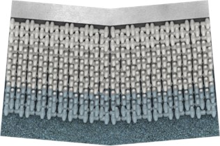
Fig. 1Shapes of Couple-Lock
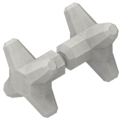
a) Surface shape
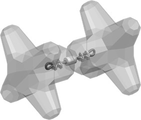
b) Internal structure
As shown in Fig. 1, the Couple-Lock, an articulated concrete armor unit developed in this study, the Couple-Lock consists of two symmetrical blocks. One symmetrical block has four legs installed in all directions on one end of the body. Since two left-right symmetrical blocks are connected with a wire rope and behave, a pair of blocks can be treated as a single block and enabling large size to cope with high waves.
In general, the concrete aromr units installed on the inclined surface of rubble mound have a weaker interlocking force when installed on the outermost side than when installed on the inner side. Due to the poor interlocking force on the outermost side, the concrete aromr unit structure may lose its function, the concrete aromr units may be damaged by the high waves, and it may be the starting point of structural instability of the breakwater.
As shown in Fig. 2, the surface of the Couple-Lock has a plurality of faceted shapes. Therefore, contact surfaces engagement may be formed to secure interlocking forces between adjacent the blocks. The Couple-Lock has a joint, so it can flexibly respond to changes in the field topography. Therefore, it is possible to actively respond to uneven and angular construction surfaces. Uniform contact points are formed on the inclined surface of rubble mound through regular staking. Therefore, it has the advantage of being able to evenly disperse the wave pressure and the load of the block on the inclined surface of rubble mound (see Fig. 3).
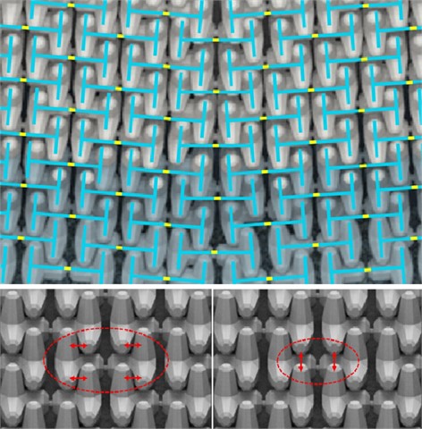
Fig. 2Couple-Lock that responds flexibly to topographical changes
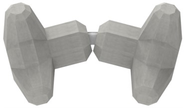
a) A convex transform of Couple Lock
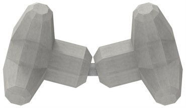
b) A concave transform of Couple Lock
Fig. 3Regular staking of Couple-Locks on the angular rubble mound
a) Top view
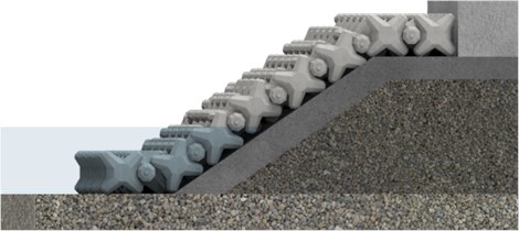
b) Side view
As shown in Fig. 4, The developed technology, The Couple-Lock, features a structure where all blocks are organically connected in all directions (up, down, left, right, front and back) to form a 3-dimensional H-chain structure. This design ensures that even if some blocks are damaged, they will not separate or detach (once installed, the blocks will not separate unless intentionally removed in the reverse order of installation). The structure does not resist waves individually but as an entire interconnected 3-dimensional H-chain structure, allowing it to flexibly and organically resist wave forces.
This three-dimensional H-chain structure is an innovative coupling structure not found in conventional wave-dissipating blocks. It is implemented through various connecting structures, such as a connection-type block structure where two segmented blocks are connected by a connecting material, a structure where four legs are formed on one segmented block, a structure where legs extend radially at 90° angles from one main body, and configurations that are symmetrical in all directions.
The Couple-Lock can complete the 3-dimensional H-chain structure with just a single layer, demonstrating excellent wave-dissipating performance.
Due to the 3D H-chain structure, it is now possible to produce high-density concrete blocks with excellent interlocking and bonding properties. These blocks are easy to handle even in linearly varying segments, maintaining the chain structure between blocks. They solve the issue of thermal expansion, allowing for the production of ultra-heavyweight wave-dissipating blocks. With high stability factor () and porosity, they exhibit superior strength and durability, ensuring structural stability and economic efficiency.
Fig. 4The 3-dimensional H-chain structure of the Couple-Locks
3. Hydrological model experiments
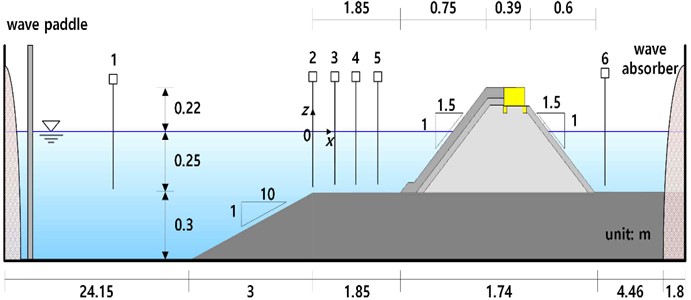
The hydraulic characteristics and stability of the Couple-Lock were analyzed through a hydraulic model experiment considering ordinary wave and storm wave conditions. The specifications of the two-dimensional wave tank used in the experiment are shown in Fig. 5.
Fig. 5Schematic drawing of wave tank
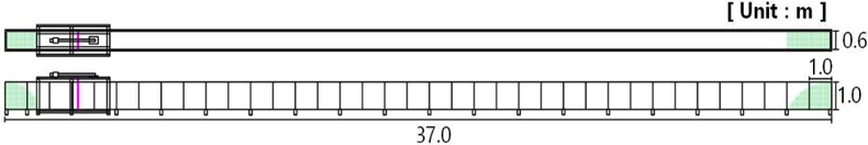
The wave tank is 37 m long, 0.6 m wide and 1 m high. And the wave-making board has a size of 0.6 m×1.0 m, and a low-friction watertight device is attached to the side of the wave-making board. A computer-controlled piston-type wave generator was used so that the servomotor acts with the frequency and voltage of the experimental wave as input signals. This wave generator can generate regular waves, irregular waves, and isolated waves, and the period range of possible waves is 0.25 to 5.6 seconds, and the maximum wave height is 0.25 m.
The scale of the model experiment was set to 1/50 after comprehensively reviewing the dimensions of the wave tank, the structure, weight of the Couple-Lock, and the experimental waves. The scale of various factors is shown in Table 1.
Table 1Scale by Froude’s law of comparison
Items | Scale | Similarity law | Prototype | Model |
Length | Lr | 1/50 | 50 (m) | 1 (m) |
Depth of water | Lr | 1/50 | 25 (m) | 0.5 (m) |
Wave height | Lr | 1/50 | 5 (m) | 0.1 (m) |
Wavelength | Lr | 1/50 | 150 (m) | 3 (m) |
Cycle, Time | Lr1/2 | (1/50)1/2 | 11 (sec) | 1.56 (sec) |
Block weight | Lr3 | (1/50)3 | 125 (kN/ea) | 1 (N/ea) |
Rate of overtopping | Lr3/2 | (1/50)3/2 | 0.1 (m3/sec/m) | 2.83×10⁻⁴ (m3/sec/m) |
The water depth in front of the actual breakwater was set to 12.5 m. Therefore, in the model experiment to evaluate the hydraulic characteristics and stability of the Couple-Lock, a similarity ratio of 1/50 was applied, and the water depth at the front of the breakwater in the wave tank was configured to be 0.25 m. In order to generate stable waves, the depth of the open sea where the wave maker is located in the wave tank is set to 0.55 m. For the breakwater placed in the wave tank, an impervious bubble step with a height of 0.3 m and a slope of 1:10 was installed to maintain a water depth of 0.25 m in consideration of shallow sea conditions. Wave absorbers were installed on both sides of the tank to minimize wave field disturbance caused by long-term irregular waves. The breakwater in the wave tank constructed for the model experiment is shown in Fig. 6.
Fig. 6Wave tank configuration
The breakwater applied to the model experiment is an inclined rubble mound type, and the detailed specifications are shown in Table 2. The foundation of the breakwater is composed of ripraps, the open sea side slope is equipped with Couple-Locks, and the inland sea side slope is composed of armor stones. The crest of the breakwater is installed with Couple-Locks in front of concrete cap.
Table 2Constituent materials of breakwater model
Items | Weight (N/ea) | Porosity |
Foundation riprap | 0.022 | 0.43 |
Armor stone | 0.212 | 0.456 |
Couple-Lock | 0.96-1.05 | 0.58 |
In order to evaluate the stability of Couple-Locks against waves, both complete Couple-Locks and wire rope cut Couple-Locks were applied together. The area of the Couple-Locks where the wire rope was cut is shown in Fig. 7.
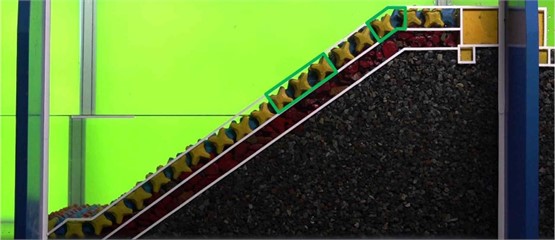
In general, the most vulnerable part of the breakwater is the front slope where the water surface is in contact. The next vulnerable part of the breakwater is the area where the crest and slope meet. Accordingly, the wire rope cut Couple-Locks was placed in the vulnerable parts. The number of the Couple-Locks used to construct the breakwater is shown in Table 3, and the model shape of the breakwater installed in the wave tank for the experiment is shown in Fig. 8.
Fig. 7Layout of the wire rope cut Couple-Locks positions
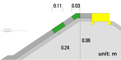
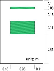
Table 3Quantity of the Couple-Locks
Items | Location | Quantity |
Complete Couple-Lock | Berm | 32 |
Front slope | 232 | |
Crest | 40 | |
Total | 304 | |
Wire rope cut Couple-Lock | Still water level | 27 |
Crest and slope meet | 9 | |
Total | 36 |
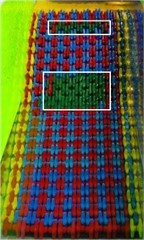
Fig. 8The Breakwater covered with the Couple-Locks
Both ordinary waves and storm waves were applied to the analysis of hydraulic performance such as reflection coefficient, transmission coefficient, and amount of overtopping waves of the breakwater, and only storm waves were considered for the stability review of the Couple Lock.
The ordinary wave used in the model experiment was generated by irregular waves with a significant wave height of 1.6 to 5.2 cm and a significant period of 0.8 to 1.3 sec in consideration of the design conditions of a significant wave height of 0.8 to 2.6 m and a significant period of 5.66 to 9.19 sec (see Fig. 9). The storm wave used in the model experiment was generated by irregular waves with a significant wave height of 9.8 to 13.7cm and a significant period of 1.4 to 2.2 sec in consideration of the design conditions of a significant wave height of 4.89 to 6.87 m and a significant period of 9.9 to 15.56 sec (see Fig. 10). In addition, to reproduce the irregular wave field, the spectrum of Bretschneider-Mitsuyasu was applied, and the frequency of the irregular wave applied the theory of Goda [13]-[14].
The reflection coefficient of the water surface wave measured from the front of the breakwater can be calculated using Goda and Suzuki’s method of separating the incident wave and the reflected wave [14]. In addition, the transmission coefficient can be calculated from the water surface waveform measured behind the breakwater.
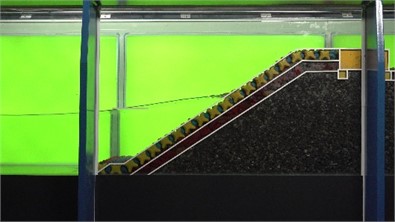
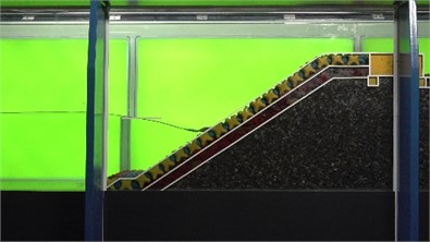
Fig. 9Time series of non-breaking condition due to the ordinary wave (H1/3 = 5.2 cm, T1/3 = 1.3 sec)

a) t/T1/3 = 2/20

b) t/ T1/3 = 4/20

c) t/ T1/3 = 6/20
d) t/ T1/3 = 8/20

e) t/ T1/3 = 10/20

f) t/ T1/3 = 12/20

g) t/ T1/3 = 14/20

h) t/ T1/3 = 16/20
i) t/ T1/3 = 18/20

j) t/ T1/3 = 20/20
Fig. 10Time series of breaking wave condition due to the storm wave (H1/3 = 13.19 cm, T1/3 = 2.2 sec)
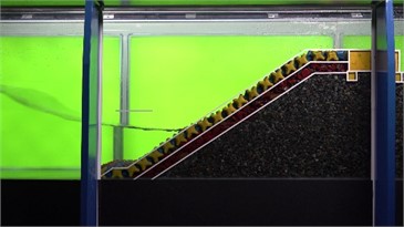
a) t/T1/3 = 2/20
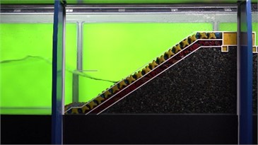
b) t/ T1/3 = 4/20
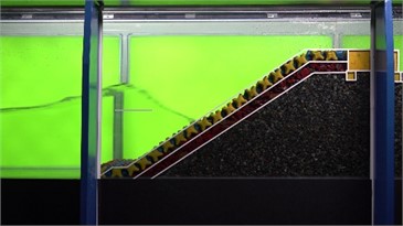
c) t/ T1/3 = 6/20
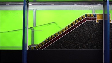
d) t/ T1/3 = 8/20
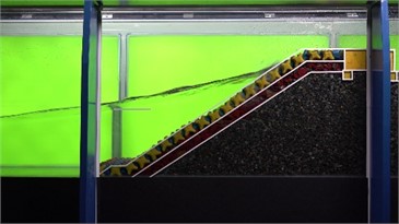
e) t/ T1/3 = 10/20
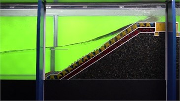
f) t/ T1/3 = 12/20
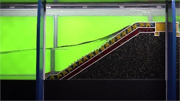
g) t/ T1/3 = 14/20
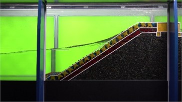
h) t/ T1/3 = 16/20
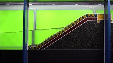
i) t/ T1/3 = 18/20

j) t/ T1/3 = 20/20
That is, the energies of the incident and reflected waves ( and ) can be calculated as integral values in the effective frequency range defined by Goda and Suzuki for spectral density estimation. Therefore, the reflection coefficient is expressed by Eq. (1):
Fig. 11Distribution of wave reflection coefficients under the action of the ordinary waves
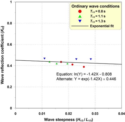
Fig. 12Distribution of wave reflection coefficients under the action of the storm waves
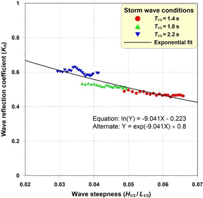
The distribution of the reflection coefficient of waves according to the action of ordinary waves and storm waves is shown in Fig. 11 and 12. The reflection coefficient in the ordinary wave condition where non-breaking wave occurs was 0.389-0.467, showing similar distributions for each wave slope. And the reflection coefficient of the storm wave conditions in which breaking waves occur was 0.462-0.629, which tended to decrease as the wave slope increased. Therefore, the average reflection coefficients of ordinary wave and storm wave conditions were calculated as 0.433 and 0.533, respectively.
For the transfer coefficient , the wave height data obtained from the wave height gauge installed behind the breakwater was separated into each frequency component wave by FFT (Fast fourier transformation). It can be calculated as in Eq. (2) using the energy ( and ) of the transmitted wave and the incident wave calculated as the sum of each frequency component and energy:
The distribution of the transmission coefficient of waves according to the action of ordinary waves and storm waves is shown in Fig. 13 and 14. The transmission coefficient under ordinary wave condition where wave overtopping does not occur was calculated as small as 0.021-0.087. The transmission coefficient in the storm wave condition was calculated to be 0.13-0.174, which indicates that the transmission coefficient increases as the wave overtopping discharge increases. The average transmission coefficients under ordinary wave and storm wave conditions were calculated as 0.046 and 0.147, respectively.
The wave overtopping discharge was measured continuously by installing a separate overtopping tank behind the breakwater. In order to reduce the error, the average value of the wave overtopping discharge per unit time/unit width measured three times (3×200×T1/3) was calculated.
Fig. 13Distribution of wave transmission coefficients under the action of ordinary waves
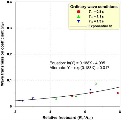
Fig. 14Distribution of wave transmission coefficients under the action of storm waves
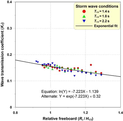
Fig. 15Distribution of wave overtopping discharge under the action of storm waves
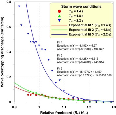
Wave overtopping occurred only during storm wave action. Fig. 15 shows the distribution of wave overtopping discharge per unit width according to the storm wave action. Among the 62 storm wave conditions, wave overtopping occurred in 50 storm waves. The wave overtopping discharge increased as the significant wave height increased, and the wave overtopping discharge increased when the significant period was long in the same wave height. The average wave overtopping discharge under the condition of T1/3 = 1.4 s was measured as 0.039 cm3/s/cm, and the average wave overtopping discharge under the condition of T1/3 = 1.8 s was measured as 0.047 cm3/s/cm. The average wave overtopping discharge under the condition of T1/3 = 2.2 s was measured as 0.321 cm3/s/cm.
The damage rate (S) of the Couple-Lock caused by waves can be calculated as the ratio of the total number of Couple-Locks to the number of Couple-Locks lost from the breakwater. In this study, the damage rate was investigated after generating waves for 1,400, 1,800, and 2,200 sec (≒1,000×T1/3). In the hydraulic experiment, some of the front slope of the breakwater was settled due to the continuous storm wave action, but no damage was caused to the Couple-Lock.
In order to calculate the stability factor (), if block breakaway damage occurs under storm wave conditions, an additional two repetitions of the experiment are conducted. When no damage was observed, the stability factor was estimated from the results by repeating the experiment twice for the case where the wave height and period were the largest under storm wave conditions. In this experiment, the Couple-Lock did not cause any damage, so it was estimated from the experimental conditions. That is, the maximum stability factor (KD) was estimated to be 18.82 under the conditions of H1/3 = 0.1373 m and T1/3 = 2.2 s, and when a Couple-Lock with a weight of 12.5 ton is used for a breakwater, up to 18 can be applied as a stability factor.
4. Conclusions
The concrete armor unit is widely used as a covering material for the breakwater. Today, with climate change, the necessity and importance of the concrete armor unit that can respond to high waves is emerging.
In this study, the Couple-Lock, a segmented concrete armor unit, was developed. Since two identical blocks are combined using a connecting material so that they correspond to each other, it is possible to increase the size. In addition, the heat of hydration can be reduced because the size of each block is small. The interlocking between the Couple-Lock is excellent, and the adaptability to field conditions with irregular ground and slopes is excellent. In particular, the Couple-Lock has excellent applicability to each part where the slope and the top meet, and was evaluated about twice as high as the stability factor () of 8 to 10 of tetrapod. Also, the Couple-Lock responds flexibly to topographical changes.
Through this study, the development of 1-layer structure using the Couple-Locks was successfully carried out, and further research on structural performance evaluation and overtopping effect through multi-layer structure using the Couple-Locks needs to be continued.
References
-
“Statistical Yearbook of Oceans and Fisheries 2021,” Ministry of Oceans and Fisheries in Korea, 2021.
-
J. S. Park, K. Kang, H.-S. Kang, and Y.-H. Kim, “Projection of the future wave climate changes over the Western North Pacific,” Journal of Korean Society of Coastal and Ocean Engineers, Vol. 25, No. 5, pp. 267–275, Oct. 2013, https://doi.org/10.9765/kscoe.2013.25.5.267
-
Y. H. Park and D. Youn, “Development of a new armor unit against high waves,” Journal of the Korea Academia-Industrial Cooperation Society, Vol. 17, No. 6, pp. 737–743, Jun. 2016, https://doi.org/10.5762/kais.2016.17.6.737
-
K. H. Hong and I. S. Jeon, “Experimental study for the hydraulic performance of octopus – A new type of armor block,” Journal of the Korean Society of Civil Engineers, Vol. 19, No. II-3, pp. 359–374, 1999.
-
T. N. Huh and C. H. Choi, “Impact analyses for the safety checks of used wave dissipation concrete block considering construction phases,” Journal of the Korea Academia-Industrial Cooperation Society, Vol. 19, No. 10, pp. 640–647, 2018, https://doi.org/10.5762/kais.2018.19.10.640
-
J.-I. Lee, G. Y. Lee, and Y.-T. Kim, “Horizontal wave pressures on the crown wall of rubble mound breakwater under non-breaking condition,” Journal of Korean Society of Coastal and Ocean Engineers, Vol. 33, No. 6, pp. 321–332, Dec. 2021, https://doi.org/10.9765/kscoe.2021.33.6.321
-
I. Safari, D. Mouazé, S. Aliasgary, G. Carpentier, and F. Ropert, “Hydraulic response and overtopping performance of single-layer double cube unit armored mound breakwater,” Journal of Marine Science and Engineering, Vol. 11, No. 7, p. 1382, Jul. 2023, https://doi.org/10.3390/jmse11071382
-
F. Vieira, F. Taveira-Pinto, and P. Rosa-Santos, “Single-layer cube armoured breakwaters: Critical review and technical challenges,” Ocean Engineering, Vol. 216, p. 108042, Nov. 2020, https://doi.org/10.1016/j.oceaneng.2020.108042
-
G. Scaravaglione, J. P. Latham, J. Xiang, A. Francone, and G. R. Tomasicchio, “Historical overview of the structural integrity of concrete armour units,” Coastal and Offshore Science and Engineering., pp. 68–98, 2022.
-
C. Peng, H. Wang, H. Zhang, and H. Chen, “Parametric design and numerical investigation of hydrodynamic characteristics of a new type of Armour block TB-CUBE based on SPH method,” Journal of Marine Science and Engineering, Vol. 10, No. 8, p. 1116, Aug. 2022, https://doi.org/10.3390/jmse10081116
-
H.-S. Yoon, H.-L. Kim, H.-W. Yu, and M.-S. Kim, “Estimation of limiting wave height for wave dissipation block (tetrapod) in Busan coast,” Journal of the Korean Society for Marine Environment and Energy, Vol. 23, No. 3, pp. 117–125, Aug. 2020, https://doi.org/10.7846/jkosmee.2020.23.3.117
-
Y. S. Lee, “Segmented break water block, piling method thereof and break water structure thereby,” Korea Patent 1020427360000, 2019.
-
H. Mitsuyasu, “On the growth of the spectrum of wind-generated waves,” Coastal Engineering in Japan, Vol. 13, No. 1, pp. 1–14, Jan. 2018, https://doi.org/10.1080/05785634.1970.11924105
-
Y. Goda and T. Suzuki, “Estimation of incident and reflected waves in random wave experiments,” in Coastal Engineering Proceedings, No. 15, p. 47, Jan. 1976, https://doi.org/10.9753/icce.v15.47
About this article

This research was supported by a Korea Agency for Infrastructure Technology Advancement (KAIA) grant funded by the Korean government (MOLIT) (RS-2023-00250434).
The datasets generated during and/or analyzed during the current study are available from the corresponding author on reasonable request.
Wan Hoon Lee was responsible for hydraulic model experiment and results analysis. Yeosub Lee was responsible for research and development of the Couple-Lock. Changhwan Jang was responsible for writing-original draft preparation, writing-review and editing, funding acquisition and supervision.
The authors declare that they have no conflict of interest.
