Abstract
The tarpaulin of PVC-coated S8210 wagons is a composite textile membrane. This material is resistant to atmospheric factors (wind, rain, snow, etc.), durable for many practical applications and can be manufactured in various colors and prints. PVC membrane material is inexpensive, soft and easy to manufacture. These materials are widely used in large-opening spatial structures due to excellent mechanical behavior and beautiful textures. The tarpaulins are made by the method of welding with high frequency currents from the material S8210. In the present paper, the tensile and tearing mechanical properties of tarpaulins intended to protect goods carried by railway wagons are presented. The results of this study can be used in establishing the appropriate utilization of the fabric, in accordance to the warp and weft directions.
Highlights
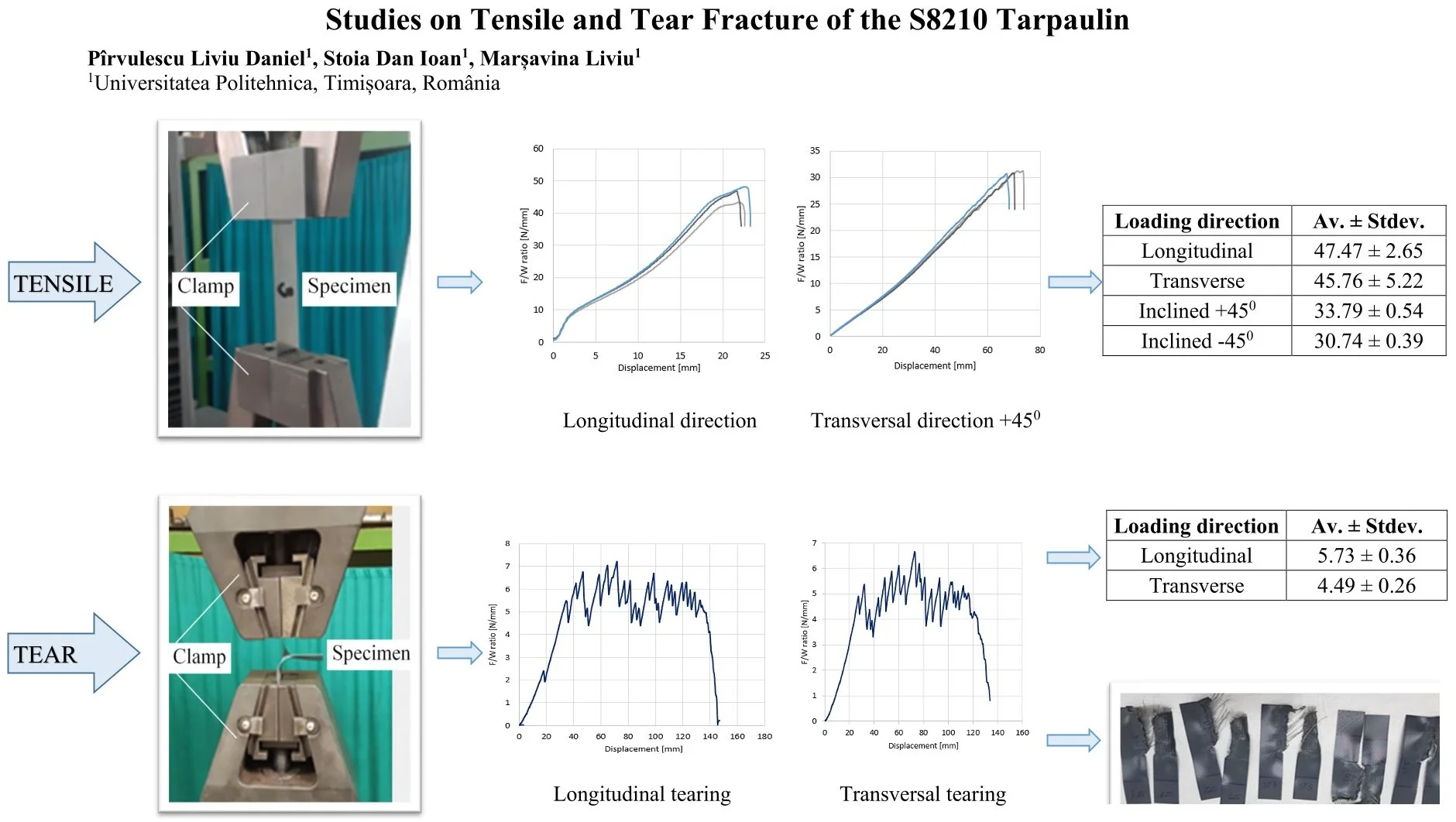
- S8210 tarpaulin material is very useful in space structures being cheap, easy to manufacture and resistant to atmospheric factors.
- From the data obtained experimentally, it is found that the mechanical behavior of the S8210 material is non-linear, inelastic and anisotropic due to the non-linearity of the component materials, the non-linear geometry of the structure and the contact friction between the component materials.
- Experimentally obtained results attest to the fact that the specimens loaded in the longitudinal direction bear the highest loads both in tension and in tearing.
- From the breaking tests, two types of failure are identified, namely: progressive failure and brutal failure. Both defects depend on the microstructure of the tarp and the friction between the warp and weft yarns.
1. Introduction
Tarpaulins have been and are widely used in various fields such as: railway wagons, coating of biogas fermenters, large-opening buildings (stadiums), inflatable boats, rescue tents etc.
Coated fabrics are especially designed for outdoor use under the action of external climatic factors. Two main types of tarpaulin are known: glass fiber coated with polytetrafluoroethylene (PTFE) and polyester fiber coated with polyvinyl chloride (PVC). Both materials are composed of an open fabric of orthogonal fibers with a layer covering the mesh on both sides [1].
The tarpaulin in PTFE is more reliable for large constructions in severe loading conditions, having good resistance to fire and high temperatures, and the waterproof Teflon layer gives it resistance to staining and repels chemicals in the air. However, glass fibers are brittle and hard to fold, which lead to degradation of mechanical properties in transport and tarpaulin construction.
PVC coated polyester fabrics are more often used due to their high cost-effectiveness compared to other tarpaulins such as Teflon, silicone or PTFE coated [2]. Tarpaulin is composed of substrate, cover and surface layer [8]. The coating is used to protect the substrate and has superior self-cleaning, anti-pollution and durability performance. Covered fabrics are composed of two families of orthogonal yarns, called warp and weft. The S8210 material foil is resistant to the action of atmospheric factors (temperature variations, ultraviolet rays etc.). The S8210 material has a smooth, lacquered and glossy face with a continuous and uniform foil over the entire surface and the back has a lacking appearance (the fabric prints are identified).
The mechanical properties of tarpaulins are nonlinear due to the complex mechanism of multi-component materials and the manufacturing process. Non-linearity mainly includes the non-linearity of the component materials and the non-linearity of the friction contact during the stretching process.
In addition, the surface of the membrane is exposed to the atmosphere during the operating period, so the mechanical properties of the membrane are affected by various loads and environments [6]. Several references are known to show the mechanical behavior of PVC tarpaulins. Junhao et al. studied the properties of uniaxial and biaxial tensile, shearing and tearing [5]. Zhang et al. studied the tearing behavior for PVC-coated fabrics with initial notch [7]. Lanlan et al. performed tensile tests on cut specimens at different angles to the direction of drawing [3].
This research led to the development of design specifications for membrane structures and determined the parameters of materials relevant to structural design. Previous studies have shown that the mechanical properties of tarpaulins are difficult to measure by several parameters.
2. Experimental analysis
The fracture of tarpaulin for railway wagons made of S8210 material was investigated. The foil was supplied by Satimpex and has a thickness of 0.46 mm and density of 800 g/m2. Samples were cut from the received foil for the tensile test having a width of 25 and 37 mm in longitudinal and transverse direction and width of 50 mm for the samples cut to 45° from the direction of traction. The samples for the tearing tests were cut according to DIN EN ISO 4674-1:2017 having a width of 50 mm. The shape and dimensions of the traction (transverse and longitudinal) and tear specimens are shown in Fig. 1.
Fig. 1The traction and tear test specimen

a) Tensile test samples (W = 25; 37 mm) TT = traverse traction; TL = longitudinal traction
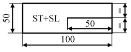
b) Tear test samples ST = transverse tear; SL = longitudinal tear
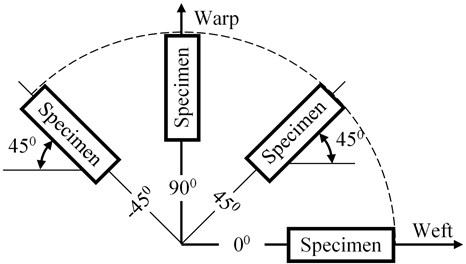
The test specimens have been cut from the overall width and length of the foil in accordance with the requirements of BS EN ISO 1421. Five sets of test specimens were cut to perform the tests. Each set shall contain five samples for each test in the longitudinal, transverse and the two inclined directions at 45° clockwise and counterclockwise from the direction of traction, Fig. 2.
Fig. 2Cutting the specimens for testing: Inclined –45; Longitudinal; Inclined +45; Transversal
The tests were carried out on the LBG 100 traction test machine with a maximum force of 100 kN located in the endowment of the Laboratory of Material Strength at the Politehnica University of Timisoara. The method of clamping the specimens for tensile and tearing loading respectively, is shown in Fig. 3.
The tests were carried out at room temperature (22 °C), the load was applied at a constant speed of 100 mm/min until the test specimens were completely broken. During the test, it is necessary that the test sample does not slip into the clamping system of the machine, does not damage the test sample and does not reduce its strength.
If the test on the broken samples showed signs of slipping due to the clamping system or if the samples were broken in the vicinity of the clamping system, these results were not taken into consideration.
Each specimen was subjected to tensile strength with a constant increasing force until fracture. The tensile strength was determined according to SR EN ISO 1421:2017 and the tear strength according to DIN EN ISO 4674-1:2017.
Five specimens from each batch were tested, the force-displacement curves being recorded by the testing machine. For each batch of samples tested, the average value of the maximum force from of the five samples belonging to the same batch was calculated.
Fig. 3Clamping of specimens for tensile and tear testing
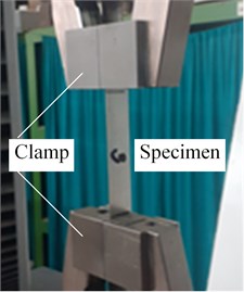
a) Tensile test
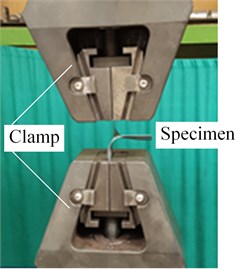
b) Tear test
3. Results and discussion
3.1. Tensile strength
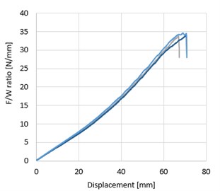
Tensile strength is an important parameter of the material, and fracture is the main way of damage of the tarpaulin structures. Fig. 4 shows typical curves for the samples tested for transverse, longitudinal and inclined direction 45° clockwise and counterclockwise. The curves represent on vertical axis the force/width ratios [N/mm] and on horizontal axis the displacement [mm].
From experiments was determined the maximum force/width ratio values for each batch of five specimens tests according to the direction of cut. The results presented in Table 1 show significant differences in force/width depending on the direction of cut for PVC coated tarpaulin.
Table 1Maximum force/width [N/mm] for the traction test according to the direction of cut
Samples | Loading direction | |||
Longitudinal | Transverse | Inclined +45° | Inclined –45° | |
Tens 1 | 43.31 | 51.14 | 33.26 | 31.30 |
Tens 2 | 48.26 | 38.25 | 34.64 | 30.66 |
Tens 3 | 48.88 | 42.60 | 33.87 | 30.87 |
Tens 4 | 46.69 | 48.12 | 33.80 | 30.20 |
Tens 5 | 50.23 | 48.67 | 33.66 | 30.66 |
Av. ± Stdev. | 47.47± 2.65 | 45.76 ± 5.22 | 33.79 ± 0.54 | 30.74 ± 0.39 |
Analyzing the results in Table 1, it is observed that better tensile strength of the tarpaulin was obtained for the samples cut in the longitudinal direction and less for samples cut at 45° counterclockwise to the direction of traction. Considering the longitudinal direction as reference group, there is no statistically significant difference between the reference and the transversal direction (p= 0.607) while significant differences are recorded between the reference group and the inclined directions (p= 0.00024 and p= 0.00020).
Fig. 4Representative curves of tensile tested specimens
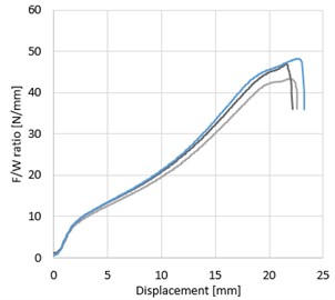
a) Longitudinal direction
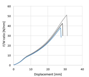
b) Transversal direction
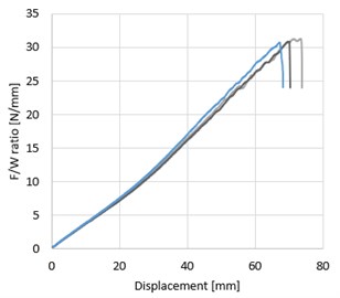
c) Inclined direction +45°
d) Inclined direction –45°
3.2. Tear strength
Tear strength is another important material parameter, and tear fracture is another way of tarpaulin failure. However, design calculations are always based on tensile strength which differs from tear strength [4]. Therefore, it is necessary to study the failure behavior of tarpaulin by tearing and take into account the results in the design.
The test samples were prepared by cutting them in half (see Fig. 1(b)) with a special knife, clamped in the test machine by the two separate arms having a width of 25 mm (see Fig. 3(b)).
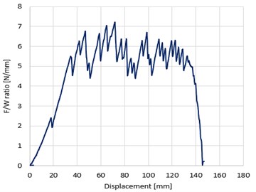
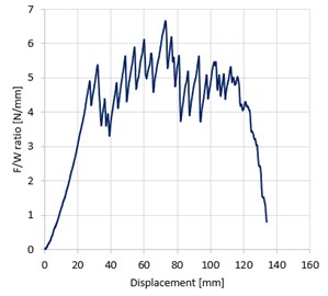
Fig. 5 shows the force/width ratio – displacement curves for the samples tested at tear in the transverse and longitudinal direction.
Fig. 5Representative curves of tear tested specimens
a) Longitudinal tearing
b) Transverse tearing
To reduce the accidental errors, five sets of specimens were tested for each case and the average value was adopted to represent the tear strength.
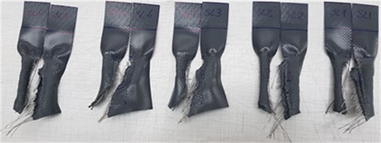
The interpretation of the results was performed according to DIN EN ISO 4674-1:2017 standard, dividing the graph (Fig. 5), starting with the first peak and ending with the last, into four equal subsections. The first subsection is deleted. From each of the other three subsections, two highest and two lowest peaks are selected. A peak for calculation is characterized by a decrease of at least 10 % in force. The broken specimens resulting from the tear tests are shown in Fig. 6.
Fig. 6Specimens broken in tear testing
a) Longitudinal specimens
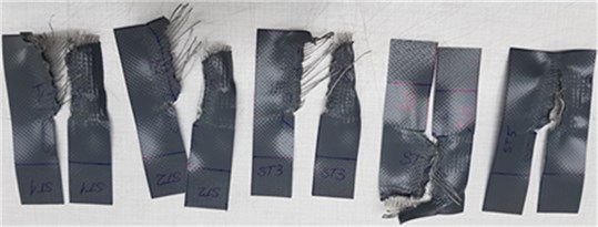
b) Transversal specimens
The obtained results are presented in Table 2. Significant differences in maximum force are observed depending on the direction of cutting for PVC coated tarpaulins.
Table 2Maximum force/width [N/mm] ratio at tear tests depending on the direction of cut
Samples | Loading direction | |
Longitudinal | Transverse | |
Tear 1 | 5.40 | 4.30 |
Tear 2 | 5.47 | 4.54 |
Tear 3 | 6.24 | 4.88 |
Tear 4 | 6.00 | 4.51 |
Tear 5 | 5.56 | 4.21 |
Av. ± Stdev. | 5.73 ± 0.36 | 4.49 ± 0.26 |
Analyzing the results in Table 2, it can be seen that the tarpaulin resists much better in the longitudinal direction than in the transverse direction at the tearing test. Statistically significant difference between longitudinal and transverse tear was recorded, p= 0.00025.
When comparing the tensile testing on the longitudinal direction with the tear testing on the same direction, highly significant differences on force/with values is recorded, p= 3.3×10⁻⁶.
Conclusions
This paper presents the tensile and tear fracture behavior for the PVC tarpaulin used to protect goods carried by railway wagons. Like any composite material, the mechanical behavior of PVC tarpaulin is characterized by non-linearity, inelasticity and anisotropy.
The following conclusions can be drawn from the present study:
1) The samples cut longitudinally after the direction of pull bear the highest loads at the traction solicitation.
2) The samples cut at 45° from the direction of drawing bear much lower loads than samples cut crosswise and longitudinally from the direction of firing.
3) Insignificant differences for the mean value at the tensile stress for the longitudinally and transversely cut samples (difference of 3.60 %) and mean values close enough for the samples cut at 45° (difference 9.00 %) are observed.
4) Fracture by tearing of samples can be of two mechanisms: progressive failure and brutal failure. The two fracture mechanisms depend on the microscopic structure of PVC-coated fabrics. Due to the fabric structure and the PVC coating, there is considerable friction between the warp and weft threads.
5) Samples cut in the longitudinal direction bear more tearing forces than those cut in the transverse direction.
References
-
B. N. Bridgens and P. D. Gosling, “Direct stress-strain representation for coated woven fabrics,” Computers and Structures, pp. 1913–1927, 2004.
-
T. D. Dinh, A. Rezaei, L. de Laet, M. Mollaert, D. van Hemelrijck, and W. van Paepegem, “A new elasto-plastic material model for coated fabric,” Engineering Structures, Vol. 71, pp. 222–233, Jul. 2014, https://doi.org/10.1016/j.engstruct.2014.04.027
-
Z. Lanlan, Z. Yingying, S. Wei, X. Junhao, and X. Jigang, “A nonlinear damage constitutive model of PVC coated fabrics,” Structures, Vol. 30, pp. 368–377, Apr. 2021, https://doi.org/10.1016/j.istruc.2021.01.027
-
B. Forster and M. Mollaert, European design guide for tensile surface structures. Bruxelles: Tensinet, 2004.
-
J. Xu, Y. Zhang, M. Wu, and Y. Zhao, “Experimental analysis of off-axis mechanical behaviors of PVC coated fabrics subjected to cyclic loading,” Polymer Testing, Vol. 80, p. 106090, Dec. 2019, https://doi.org/10.1016/j.polymertesting.2019.106090
-
Y. Zhou, Y. Li, Z. Shen, L. Wang, and Y. Tamura, “Numerical analysis of added mass for open flat membrane vibrating in still air using the boundary element method,” Journal of Wind Engineering and Industrial Aerodynamics, Vol. 131, pp. 100–111, Aug. 2014, https://doi.org/10.1016/j.jweia.2014.05.007
-
Y. Zhang, J. Xu, Y. Zhou, Q. Zhang, and F. Wu, “Central tearing behaviors of PVC coated fabrics with initial notch,” Composite Structures, Vol. 208, pp. 618–633, Jan. 2019, https://doi.org/10.1016/j.compstruct.2018.09.104
-
Z. Yingying, X. Junhao, and Z. Qilib, “Advances in mechanical properties of coated fabrics in civil engineering,” Journal of Industrial Textiles, Vol. 48, pp. 255–271, 2016.
-
“SR EN ISO 1421:2017, Rubber-or plastics-coated fabrics – Determination of tensile strength and elongation at break,” 2017.
-
“BS EN ISO 4674-1: Rubber-or plastics-coated fabrics – Determination of tear resistance, Part 1: Constant rate of tear methods,” 2016.
-
“SIOEN COATING, S8210 Technical Data Sheet”, 2016. https://leykom.ro/pub/media/file/s8210/fisa tehnica s8210.pdf.
About this article
The authors have not disclosed any funding.
The datasets generated during and/or analyzed during the current study are available from the corresponding author on reasonable request.
The authors declare that they have no conflict of interest.

