Abstract
Although drone appears in different applications, such as environmental inspection, agriculture or transportation, some aspects require more studies to clarify the efficient outcomes. One of them is to investigate the filtering performance such as Kalman and Complementary filters when the autonomous aerial system (AAS) handles its mission. However, it lacks the systematic research about these filters to provide the proper evaluation. Therefore, in this paper, the research topic related to AAS model to indicate the filtering effects in the agricultural application for making an alternative solution is presented. Firstly, the mathematical representation of system model is established in order to describe the dynamical performance and motion constraints. Then, the theory of filter structure is implemented to estimate the system state. The proposed design is validated in both numerical simulation and experiments. The system parameters that are monitored, include angular values of roll, pitch and yaw in three axes, motion parameters and its trajectories. By utilizing various sensing devices such as gyroscope, accelerometer and compass in real-world hardware, the experimental results could evaluate more precise and efficient design. The findings of this study are to (1) propose the model of AAS and proper filters, (2) launch the verified process and calibration, and (3) demonstrate the competitive performance among filters. From these results of our work, it could be clearly seen that the AAS plays an important role in daily applications and the related topics are still attractive.
1. Introduction
The research of quadcopters has become an attractive topic in industrial applications and monitoring fields due to their quick development and easy execution [1]. It is stated that this system still plays a crucial role for investigators in many years. In [2], inspectors were considered to use a quadrotor as one of the important methods to verify the transportation infrastructures such as a tunnel or a bridge. This research emphases on innovating the position control without using the global positioning system (GPS) and offers a solution for detecting a tethered quadrotor's airframe location from the length and tension or force of the tether.
The problem of state estimation becomes one of the popular topics in the aerial vehicle system. Commonly, many researchers chose the filtering approach to give a solution for these problems. However, various filter technologies have been utilized to estimate the system state of aerial vehicle. Several enhanced filters, for example, particle filters, are difficult to be computed and have a high cost of labor. It requires a powerful microprocessor to be managed in the control board. Reversely, some filters, for instance Kalman filter and Complementary filter, reveal the effectiveness and are popular because of their frequency filtering performance in the linearization system [3]. Dissimilar studies developed the Kalman filter [4] in the flight control subject. To estimate the system state at specific attitude or hovering the air vehicle, authors [5] adjusted the typical Kalman filter to enhance the adaptive response. The output values are computed by using a multiple extended Kalman filter. The state observer obtains data from different sensors such as accelerometers, gyroscopes and GPS. The study in [6] introduced an unscented Kalman filter by using the three-axes attitude identification scheme as the system observer. It operates resourcefully, but needs computational capability considerably. Additionally, this approach is also useful to trace the motion [7-9]. The desired filtering data is provided from a small inertial/magnetic sensor. As well, the extended Kalman filter is proper for an uncertain system which contains the nonlinear components. It could be embedded into a pixhawk module that satisfies the further optimization operation of the attitude detection [10]. The px4 or pixhawk module is also combined with an open-source platform, for example gazebo, to develop the hardware-in-the-loop [11].
On the other hand, a method of filter techniques is to integrate a Complementary filter [10] which has little computational complexity in the aerial vehicle system. Owing to the simple framework and high efficiency, many investigators and developers are concerned to research the attitude estimation. In [11, 12], researchers indicated that the high-order linear model of Complementary filter is globally asymptotically stable. Two kinds of filter, named as direct and passive, are completed as the work presented in [3]. Moreover, the proposed design is perfectly deterministic while it is based on the linear Complementary filter. This work is considered as the deterministic attitude estimation algorithm.
Kalman filter and Complementary filter are implemented correspondingly in the model of quadcopter to achieve the response in this work. The key contribution is to launch the performance of each filter in quadrotor to prove in which case it can be valuable. The rest of this article is structured as follows. Section 2 briefly reviews the previous works and describes the theoretical principles to estimate the orientation and acceleration in the real-world applications [12]. In Section 3, the mathematical models of both Kalman filter and Complementary filter are depicted basically. Sequentially, the motion analysis of aerial vehicle are demonstrated in Section 4. The theoretical results in Section 5 are simulated to visualize the effective design. Then, several experiments in Section 6 are established to verify our contributions. In Section 7, the conclusions are presented.
2. Investigation of theoretical principle
2.1. Problem statement
In detail, the Kalman filter is commonly known as a solution for state estimation in the unmanned aerial vehicle. The nonlinear observer [13], which produces an exogenous signal, ensures the globally asymptotical stability. This signal is to generate the linearized model for the Kalman filter to accurately estimate a quadcopter's attitude. Unlike many observers, the adaptive high-gain extended Kalman filter is validated to converge [14] globally. This is innovated by varying the high-gain parameter according to a metric. Although it presents several advantages in state estimation and good filtering properties, it still needs to increase the sensitivity to large perturbations. With the simpler design but the same structure, the extended Kalman filter model using the real sensor measurements to estimate correctly the measurement noise that is established [15]. In the complicated platform such as manipulating unmanned aerial vehicles, state estimation is a challenge due to inherent couplings, nonlinearities, and uncertainties, so that the extended Kalman filter might not be applicable. The other form of this filter that includes two options of the unscented Kalman filter, is employed to address the state estimation problem [16]. The improvement in estimation accuracy, overall control performance, and algorithm execution time compared to the other extended Kalman filters is solidly confirmed. In the other approach [17], a magnetic and inertial measurement unit provides raw data consisting of noise, bias, and drift, to feed into the motion controller of Quadcopter. The data fusion algorithms from the Madgwick, Mahony, and extended Kalman filter are competitive to significantly reduce these errors. Though, this research does not reveal the superior performance in real-world applications. Moreover, the magnetic measurement from low-cost sensors is inappropriate for precise control in autonomous aerial vehicles.
For a linear-like model, the Complementary filter is efficient concerning noise and the gyro bias estimation. This n-order direct and passive filter combined with Three Axis Attitude Determination (TRIAD) scheme is proposed to launch an attitude estimation solution [18]. In the open-source platform [19, 20], this kind of filter becomes the feasible method to determine the whole system's dynamics. Owing to the efficient characteristics, the built-in filter could be very easy to tune so the accurate measurement would be considerably cheap. For advanced applications, a novel attitude representation consisting of four-dimensional parameters is recommended for an intuitive interpretation [21]. Particularly, a complementary filter based on the new representation is rather natural than the filter that has magnetic separation property where pitch and roll angles are not affected by the magnetic disturbances. In summary, most of the previous works in this field are totally mentioned in Table 1.
Table 1The state-of-art researches of related topic
Category | Author(s) | Application(s) | Advantage(s) | Disadvantage(s) |
Complementary filter (CF) | Mark E. et al [22] | Attitude estimation on fixed-wing Unmanned Aerial Vehicle (UAV) | It indicates significant potential as a simple and robust attitude filter for small-scale UAV | The accuracy estimation is still limited |
Jin W. et al [23] | Magnetic-based fusion for fast attitude estimation | This approach is superior in calculation complexity and better precision | The gain should be adapted with different circumstances | |
Tae S. Y. et al [24] | Using MEMS sensors to schedule the gains for attitude and heading reference system | The noise corruption from accelerometer and drift error from gyro could be overcome | The innovative computation should be employed if required fast filtering response | |
Sebastian O. H. et al [25] | An extended complementary filter for whole body estimation | The results specify the novel compensation scheme efficiently and robust | The power assumption must be evaluated | |
Kalman filter (KF) | Welch, G., & Bishop, G. [26] | An introduction to Kalman filter: discrete KF and extended KF | The popular KF is to estimate the discrete-time control by a linear stochastic method while extended KF could evaluate the uncertain process by a nonlinear stochastic equations | In the complex environment, the gain-scheduling should be mentioned for better estimation |
Thomas M. and Daniel S. [27] | An extended KF for mobile robot in the Robot Operating System (ROS) environment | It supports an unlimited number of inputs from various sensor types | More state estimation nodes, linear acceleration support and covariance override are essential to implement | |
Ivan P. et al [28] | Gain-varying for dynamic positioning in marine vessel | The update rules for covariance matrices assist to achieve significant improvement in state estimation | The practical tests are required to validate the real-time performance |
It is necessary to emphasize that the gyroscope provides inaccurate and less noisy measurement. Nevertheless, due to the integral factor, the cumulative error occurs, and the result tends to be drifted, even when the system locates in the original point. The gyroscope’s results are only available in the short term. An accelerometer cannot evaluate the correct yaw angle and is sensitive to vibrate when external forces appear. Therefore, the utilization of filters that synthesize the signals from both gyroscope and accelerometer is to carry out the proper driving commands. In any mission, the attitude estimation is crucial for Quadcopter to maintain the tracking trajectory. Nevertheless, there is no research topic to discuss the comparative performance between Kalman filter and Complementary filter for such a case.
2.2. Angular estimation of aerial system
In order to use the BoosterPack module, it must be calibrated to the center of gravity (CoG) of the system. The rotation matrix of the system is described:
where Φ, θ, Ψ are roll, pitch, and yaw angles, respectively.
Assume that R1 is fixed to the earth inertial coordinate, R2 is parallel to R1 and located at the CoG of system, R3 is tied to the body of system and located at its CoG.
Due to a small Euler angle, the angular velocity of system in the R3 coordinate is as follows:
2.3. Accelerating estimation of aerial system
Consider that the system has a linear acceleration ar and is put in gravitational acceleration. Assume that linear acceleration is very small (ar≈ 0), and BoosterPack has placed its z-axis along with gravitational acceleration direction. The rotation matrix is called as R:
Hence, Euler angles can be evaluated from roll, pitch and yaw sensor readings:
As a result, the rotation matrix is written as follows:
The values of roll and pitch angle can be estimated as follows:
3. Mathematical model of filters
3.1. Complementary filter design
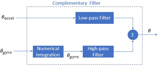
To overcome the drifted problem in the gyroscope and to lessen high-frequency noise from an accelerometer, a Complementary filter is recommended to evaluate angles θestimate based on the variation of speed ˙θgyro from a gyroscope. Later, it is added with angles θaccelerometer from the accelerometer as Fig. 1(a). It is considered to have small values, and the estimation of roll value Φ and pitch value θ are known, respectively:
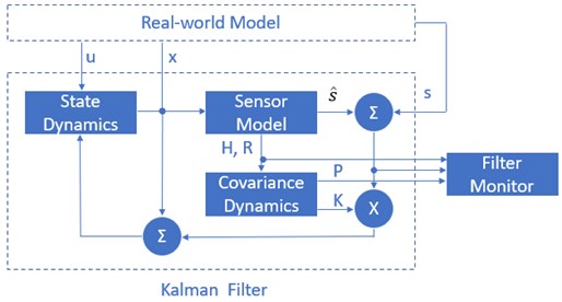
Fig. 1Structure of a) Complementary Filter and b) Kalman Filter
a)
b)
The superiority of the Complementary filter mainly concentrates on the parameter γ. In this filter, a delay time happens in the output signal (regularly because of the low-pass filter of accelerometer and high-pass filter from gyroscope). The more γ value is near to 1, the better quality this filter has. However, the estimation of the sensor readings, which are varied fastly, takes a longer convergent time. It requires to take much effort to estimate the yaw angle directly from an accelerometer, so presently, we still apply values inferred from a gyroscope and accept the drifted phenomenon. By using more magnetic sensors, this problem will be solved.
3.2. Kalman filter design
The Kalman filter's basic block diagram, which is based on the Complementary filtering principle, is given in Fig. 1b. Vector XTk=[x˙x] is in the input state, including angle (x) and angular velocity (˙x). The system state is described below:
where Uk is the vector control inputs. A is the state transition matrix applied to each system state Xk-1 on the system state Xk. B is the control input matrix that applied each control input parameter in the vector Uk. ωk is the process noise terms for each parameter in the state vector. Furthermore, s and ˆs are the sensor output and its estimation. K is the Kalman gain matrix. The process noise is assumed to be drawn from a zero-mean multivariate normal distribution N with covariance given by P(ω)~N(0,Qk).
By several measured approaches, at time k, an observation Zk of the true state Xk is made according to the below formula:
where H is the transformation matrix that maps the state vector parameters into the measurement domain. Vk is the observed noise assumed to be zero-mean Gaussian white noise with covariance given by P(V)~N(0,Rk).
4. Motion analysis for aerial vehicle
It is considered that Quadcopter is a solid object to be abided by forces such as the total force of motors and moments. In Fig. 2, a model of a quadrotor is analyzed. Each motor produces a force Ti to lift up and a moment Mi to turn the Quadcopter. The gravitational force is usually located at the origin and is directed towards the center of the earth.
Fig. 2Modeling analysis for aerial vehicle
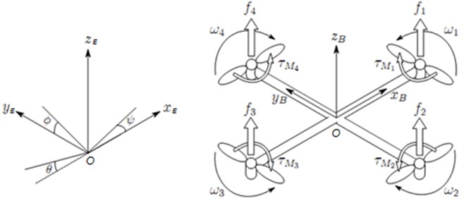
{E}=[xE,yE,zE], {B}=[xB,yB,zB] and {CSv}=[xv,yv,zv]are the inertial coordinate, body coordinate, and vehicle coordinate, respectively. x,y,z which are frames in the centroid of quadcopter model, correspond xE,yE,zE axes in the frame system {E} and xB,yB,zB axes in the frame system {B}.
Matrix REB: is the rotation matrix from frame {B} to frame {E}:
Matrix RBE: is the rotation matrix from frame {E} to frame {B}:
Position vector ξE in frame {E} and linear velocity vector VBin frame {B} are related as follows:
Matrix T is defined to perform the relationship between the angular velocity vector vB in frame {B} and frame {E}:
Using the Newton’s 2nd rule to the translational motion, the dynamic equation of system is analyzed [19]:
where VB=(u,v,w)T, ωB=(p,q,r)T and applied torque τ=[τϕτθτψ]T.
From the Newton’s 2nd rule to rotational motion, the following can be gotten:
Assume that aerial vehicle has symmetric architecture and axes in {B} coordinate are the same with inertial axes of Quadcopter:
Generally, the gravitational force FEg is determined as FEg=m[00g]T. Similarly, we can have gravitational force FBgin frame {B} as FBg=RBE,FEg=mg[-sinθsinϕcosθcosϕcosθ]T.
The quadrotor suffers forces fi from 4 Brushless DC (BLDC) motor to form total upward thrust force FBf in frame {B} as FBf=[00-f]T with b as the thrust factor:
Therefore, the total force that acts on Quadcopter is summarized:
Then, torque value is achieved by applying the Newton’s 2nd rule to rotational motion:
where L=Jωb is the angular moment. The Coriolis equation is applied to evaluate the time derivative of the angular moment in the body coordinate.
From Eq. (23), the torque that demonstrates a model of the quadrotor is specified as follows:
The length from Ob to BLDC motor, d is a drag element, and Ω1,Ω2,Ω3,Ω4 are angular velocities of motor 1, motor 2, motor 3, and motor 4, respectively.
To unify, the total force is applied to frame {E} as follows:
Later, from Eq. (21), the linear and angular accelerations are formed:
where U1,U2,U3,U4 are control signals:
There is air resistance, which affects the quadrotor in the outside environment. Thus, the air drag force can be counted as:
where Cd, ρ, S and v are drag coefficient, the mass density of the air flow, reference area of the object, and the object’s speed relative to the air flow correspondingly. In reality, the actual speed endures the limited barriers that cannot be overcome as follows:
5. Results of numerical simulation
In this section, all simulations are verified with parameters as in Table 2. In the Complementary filter, γ varies from 0.96 to 0.98. Also, R is 0.6~0.8 for Kalman filter. The motion of the Quadcopter in the z-axis is illustrated as follows:
To track the motion on the z-axis, the roll angle and pitch angle must equalize to zero. The force which is provided by each motor is computed as Fbalance=3, 2.9, 81/4 = 7,848 N. Hence, a force to lift up must be larger than Fbalance. In this case, F=4.8 = 32 N is chosen. This force should be smaller than Flimit= 50 N in each motor. The simulation result in the z-axis is shown in Fig. 3(a).
Table 2Modeling parameters of aerial vehicle
Parameters | Symbol | Value | Unit |
Total weight | M | 3.5 | kg |
Moment of inertia (x-axis) | IX | 0.0156 | Kg.m2 |
Moment of inertia (y-axis) | IY | 0.0127 | Kg.m2 |
Moment of inertia (z-axis) | IZ | 0.0384 | Kg.m2 |
Gravitational acceleration | G | 9.81 | m/s2 |
Distance from Ob to motor | L | 0.315 | m |
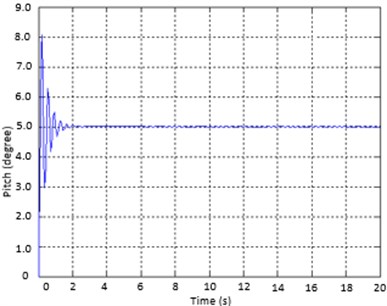
If pitch angle and yaw angle are zero, roll angle is approximately 5 degrees; then Quadcopter moves along the y-axis. The motion of the quadrotor in Fig. 3(b) and Fig. 4(a) is demonstrated below. From the results, settling time is 1,73 s approximately, and overshoot is 32,6 % which must be less than ±3o):
In this case, the system tries to achieve the predetermined attitude on the z-axis during the first 10 s. Therefore, the slope of the position graph on the y-axis is low. Similarly, the roll angle and yaw angle are zero. Pitch angle equals -5 degrees, and then the drone moves along the x-axis. The Trajectory of Quadcopter in Fig. 4(b) and Fig. 3(c) is computed as follows. It is measured that settling time is 1,59 s roughly and overshoot is 27,3 %:
Fig. 3Simulation results of system parameters on a) Z-axis, b) Y-axis, and c) X-axis

a)

b)

c)
Fig. 4Simulation results on a) pitch angle and b) roll angle
a)
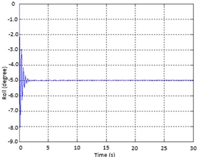
b)
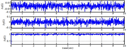
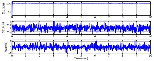
With out best knowledge, to achieve the better performance, the tuning process of filter is reasonably based on our experiences. For the pitch angle estimation, the component in high frequency is from the integrating pitch rate of gyro output while using the sensitivity of accelerometer to gravity direction is for the one in low frequency. The gain γ is tuned so that the estimated angle is wholly compensated in steady state. Similarly, the trial-and-error approach is appropriate to adjust the proper values for covariance matrix in Kalman filter. Using the above constraints, it is programmed in Matlab environment to mimic the performance of aerial vehicle in 3D space as Fig. 5(a). To imitate the real-world circumstance, the Gaussian function that plays as noise, is added to the system model. The output responses of velocity, acceleration and compass are gained in Fig. 6 in respect to data from gyroscope, accelerometer and compass measured sensor. Consequently, it can be understood clearly that these results of proposed design are reasonable and feasible.
Fig. 5a) Theoretical simulation of tracking trajectory and b) experimental test in practice
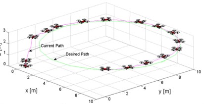
a)
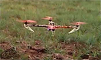
b)
Fig. 6Simulation results of feedback signals from a) gyroscope, b) accelerometer and c) compass sensor
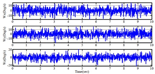
a)
b)
c)
6. Results of experimental validation
In these experiments, the previous section's design is employed to verify as follows: open-loop control scheme in x, y, and z-axis, PID control scheme in roll angle to drive left or right, and PID control scheme in pitch angle to drive forward or backward. The gains KP, KI and KD of PID controller are 1.3, 0.004 and 18 respectively. To control the exact yaw angle is not a topic in this research. BoosterPack module is attached to the drone and is supervised by mobile and host through GUI. γ, for Complementary filter, varies from 0.96 to 0.98 and R, for Kalman filter, is 0.6~0.8 so that the sensor achieves good performance. As a result, they are selected as the best suitable values (γ=0.9725, R=0.6137).
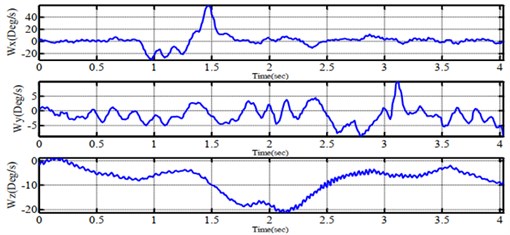
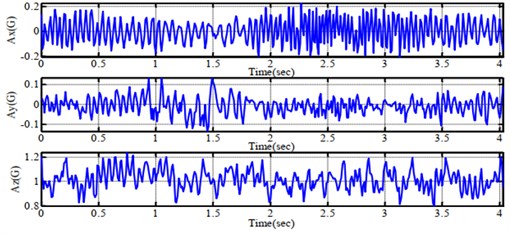
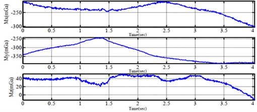
Fig. 7Experimental performance of feedback signals from a) gyroscope, b) accelerometer and c) compass sensor
a)
b)
c)
In the initializing stage, the CPU sets predetermined values for inputs, outputs, and peripheral devices when power is on. The main program will run in a loop as order; i.e. (1) Read raw data from the attached sensors; (2) Process data via sensor fusion filter (Kalman filter or Complementary filter); (3) Read RF signal from a remote controller, combine with handling values from the filter, these signals are inputted in the PID scheme to compute pulses for motors; (4) After delivering pulses to ESC, CPU transfers feedback data to a ground station.
In Fig. 7(a) and Fig. 7(b), the Complementary filter gets values of the gyro as major factors and accelerometer values as minor sources. Hence, the fluctuation which is created by both motors and propellers, indicates the accelerometer's angles. The evaluated angle from Complementary filter is more constant than that of the Kalman filter. Nonetheless, the drift phenomenon of about ±0,5° still remains. On the other hand, the Kalman filter's performance in Fig. 8(a) and Fig. 8(b) obtains the angles from an accelerometer to calculate the practical angle. It mentions the fact that this filter carries out more precise values than it was expected. However, the pulse modulation signal to each driving motor belongs to the vibration of the system.
Fig. 8Experimental performance of errors for a) roll angle, b) pitch angle and c) yaw angle when testing on one-axis by complementary filter

a)

b)

c)
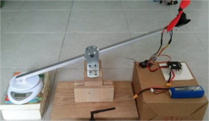
In order to examine the balancing capability on one axis, the experiment in Fig. 9(a) is performed to investigate the hardware of the system. This aerial system is suspended on a stick, and the controller tries to keep the fixed angle of 10, 30 and –35 degrees. In Fig. 10, several angular values are obtained by testing on one axis. The system testing is started in 1.5 s and the system is balanced in 5 s. Later, a stick is turned to the left, the point is balanced during 3 s. The AAS retains the predetermined angle within 8 s.
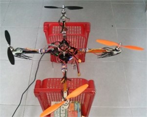
Fig. 9Experimental balancing test on a) one-axis and b) six-axes
a)
b)
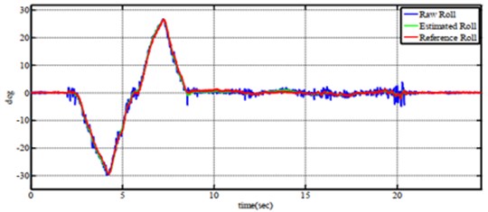
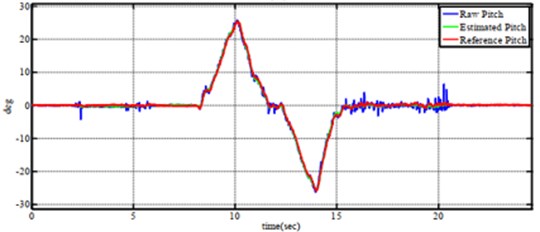
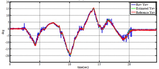
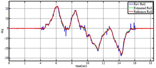
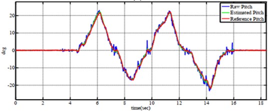
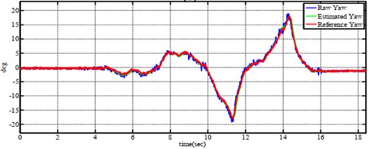
In the test scenario of six-axes motion shown in Fig. 9(b), four wings are free, and the body frame is hung by a shaft in order to evaluate the balancing ability. In Fig. 11, the experimental results of tracking angles are completed by Complementary filter correspondingly whilst Fig. 12 reveals the errors of angular values. At the sequence of 3 s, the whole system is turned on. After a few seconds, the aerial vehicle is elevated from the ground and reached to a stable position. Again, in Fig. 13 and Fig. 14, the same test conditions are employed for the Kalman filter. The autonomous aerial vehicle can slightly fluctuate around the equilibrium point with ±3 degrees, though it bears the external disturbances in the outdoor surrounding. From the above results, it can be understood easily that theComplementary filter is more advantageous than the Kalman filter in the view of the simple implementation and easy understanding. However, the filtering results from the Kalman filter produce better precision and stable performance. There is a trade-off between the Complementary filter and Kalman filter when they are integrated into the autonomous system. In Fig. 5(b), quadrotor performs well while the PID controller adapts with excellent tuning parameters based on the experiences of operator.
Fig. 10Experimental performance of errors for a) roll angle, b) pitch angle and c) yaw angle when testing on one-axis by Kalman Filter

a)

b)

c)
Fig. 11Tracking performance of a) roll angle, b) pitch angle and c) yaw angle when tesing on six-axes by complementary filter
a)
b)
c)
Fig. 12Experimental performance of errors for a) roll angle, b) pitch angle and c) yaw angle when tesing on six-axes by complementary filter

a)

b)

c)
Fig. 13Tracking performance of a) roll angle, b) pitch angle and c) yaw angle when tesing on six-axes by Kalman Filter
a)
b)
c)
Fig. 14Experimental performance of errors for a) roll angle, b) pitch angle and c) yaw angle when tesing on six-axes by Kalman Filter.

a)

b)

c)
Table 3Comparative performance among similar researches
Author(s) | Achievement(s) | Benefit(s) | Future works |
Qingquan Yang and Lingling Sun [31] | A novel data fusion based on Fuzzy Complementary Kalman filter for attitude estimation is presented. The system error as state variables of Kalman filter to compensate the attitude angle, later Complementary filter evaluates the attitude. The fuzzy scheme is to adopt the updated gains of Complementary filter. | The robustness and accuracy of filter are ensured | The rapid response of this method should be considered due to vision data |
Zhao L. et al [32] | Using both data fusion technique and Kalman filter to estimate the nonlinear state with delayed measurements is the aim of this study | The faults in speed and accuracy in the nonlinear polymerization process is compensated | It can not adapt with rapid response and complex high-dimensional process |
Our approach | Validation of simulation performance as well as experimental outcomes between two well-known filters has been presented | The output results might be a solid evidence for learners and practitioners to explore the aerial system | It requires more investments on gain-varying using intelligent scheme |
To summarize the technical specifications, the competitive descriptions among related researches have been indicated in Table 3. The outcomes of each approach were noted to illuminate the main advantages and the applied fields.
7. Conclusions
In this paper, the comparative investigation of Complementary filter and Kalman filter for the aerial vehicle control is made. Firstly, a theoretical model is applied to estimate the orientation and acceleration. Then, the developmental theory of two filters is launched to realize the innovative idea. These works are later employed in the platform of AAS to insist on major factors in both filters while the kinematics and dynamics of the quadrotor are analyzed in terms of implementation. Based on the numerical simulation and experimental tests, the proper selection of effective filters for low-cost, feasibility, and practical applications in the environment, automation, and agriculture has been validated.
Future perspectives shall be mentioned. From these results from both simulation and experiment, the data fusion has a potential to be investigated among different sensing instruments such as digital camera, inertial sensor and positioning sensor in order to enhance the system performance. In the other approach, the advanced control scheme that automatically adjusts the tuning gains of filter should be noticed. Moreover, the integrating design of both Kalman and Complementary filter into one platform may be more advantageous.
References
-
B. Yuksel, G. Buondonno, and A. Franchi, “Differential flatness and control of protocentric aerial manipulators with any number of arms and mixed rigid-/elastic-joints,” in 2016 IEEE/RSJ International Conference on Intelligent Robots and Systems (IROS), pp. 561–566, Oct. 2016, https://doi.org/10.1109/iros.2016.7759109
-
H. A. M. Tran, H. Q. T. Ngo, T. P. Nguyen, and H. Nguyen, “Research on aerial vehicle for robust navigation system under natural disaster,” in 2018 4th International Conference on Green Technology and Sustainable Development (GTSD), pp. 306–311, Nov. 2018, https://doi.org/10.1109/gtsd.2018.8595612
-
C. Yang, Z. Gao, and F. Liu, “Kalman filters for linear continuous‐time fractional‐order systems involving coloured noises using fractional‐order average derivative,” IET Control Theory and Applications, Vol. 12, No. 4, pp. 456–465, Mar. 2018, https://doi.org/10.1049/iet-cta.2017.0817
-
P. G. Medewar, M. Yadav, and H. G. Patel, “A comparison between nonlinear estimation based algorithms for mobile robot localizations,” in 2019 IEEE 1st International Conference on Energy, Systems and Information Processing (ICESIP), pp. 1–6, Jul. 2019, https://doi.org/10.1109/icesip46348.2019.8938237
-
M. Ghobadi, P. Singla, and E. T. Esfahani, “Robust attitude estimation from uncertain observations of inertial sensors using covariance inflated multiplicative extended Kalman filter,” IEEE Transactions on Instrumentation and Measurement, Vol. 67, No. 1, pp. 209–217, Jan. 2018, https://doi.org/10.1109/tim.2017.2761230
-
A. Shukla and H. Karki, “Application of robotics in onshore oil and gas industry-A review Part I,” Robotics and Autonomous Systems, Vol. 75, pp. 490–507, Jan. 2016, https://doi.org/10.1016/j.robot.2015.09.012
-
H.-Q.-T. Ngo, T.-P. Nguyen, V.-N.-S. Huynh, T.-S. Le, and C.-T. Nguyen, “Experimental comparison of Complementary filter and Kalman filter design for low-cost sensor in quadcopter,” in 2017 International Conference on System Science and Engineering (ICSSE), pp. 488–493, Jul. 2017, https://doi.org/10.1109/icsse.2017.8030922
-
H. Ahmed and M. Tahir, “Accurate attitude estimation of a moving land vehicle using low-cost MEMS IMU sensors,” IEEE Transactions on Intelligent Transportation Systems, Vol. 18, No. 7, pp. 1723–1739, Jul. 2017, https://doi.org/10.1109/tits.2016.2627536
-
H. A. M. Tran, H. Q. T. Ngo, T. P. Nguyen, and H. Nguyen, “Design of green agriculture system using internet of things and image processing techniques,” in 2018 4th International Conference on Green Technology and Sustainable Development (GTSD), pp. 28–32, Nov. 2018, https://doi.org/10.1109/gtsd.2018.8595663
-
L. Feng and Q. Fangchao, “Research on the hardware structure characteristics and EKF filtering algorithm of the autopilot PIXHAWK,” in 2016 Sixth International Conference on Instrumentation and Measurement, Computer, Communication and Control (IMCCC), pp. 228–231, Jul. 2016, https://doi.org/10.1109/imccc.2016.128
-
K. D. Nguyen and C. Ha, “Development of hardware-in-the-loop simulation based on gazebo and pixhawk for unmanned aerial vehicles,” International Journal of Aeronautical and Space Sciences, Vol. 19, No. 1, pp. 238–249, Mar. 2018, https://doi.org/10.1007/s42405-018-0012-8
-
L. Benziane, A. El Hadri, A. Seba, A. Benallegue, and Y. Chitour, “Attitude estimation and control using linearlike complementary filters: theory and experiment,” IEEE Transactions on Control Systems Technology, Vol. 24, No. 6, pp. 2133–2140, Nov. 2016, https://doi.org/10.1109/tcst.2016.2535382
-
C. Xu, C. Xu, C. Wu, J. Liu, D. Qu, and F. Xu, “Accurate two-step filtering for AUV navigation in large deep-sea environment,” Applied Ocean Research, Vol. 115, p. 102821, Oct. 2021, https://doi.org/10.1016/j.apor.2021.102821
-
J. Keighobadi, M. Hosseini-Pishrobat, J. Faraji, and M. N. Langehbiz, “Design and experimental evaluation of immersion and invariance observer for low-cost attitude-heading reference system,” IEEE Transactions on Industrial Electronics, Vol. 67, No. 9, pp. 7871–7878, Sep. 2020, https://doi.org/10.1109/tie.2019.2944062
-
V. Gudmundsson, H. Kristinsson, S. Petersen, and A. Hasan, “Robust UAV attitude estimation using a cascade of nonlinear observer and linearized Kalman filter,” in ASME 2018 Dynamic Systems and Control Conference, Vol. 51913, Sep. 2018, https://doi.org/10.1115/dscc2018-9123
-
H.-Q. Zhai and L.-H. Wang, “The robust residual-based adaptive estimation Kalman filter method for strap-down inertial and geomagnetic tightly integrated navigation system,” Review of Scientific Instruments, Vol. 91, No. 10, p. 104501, Oct. 2020, https://doi.org/10.1063/5.0019305
-
W. Liang, “Attitude estimation of quadcopter through extended Kalman filter,” Doctoral dissertation, Lehigh University, 2017.
-
H. Bonyan Khamseh, S. Ghorbani, and F. Janabi-Sharifi, “Unscented Kalman filter state estimation for manipulating unmanned aerial vehicles,” Aerospace Science and Technology, Vol. 92, pp. 446–463, Sep. 2019, https://doi.org/10.1016/j.ast.2019.06.009
-
S. A. Ludwig and K. D. Burnham, “Comparison of Euler estimate using extended Kalman filter, madgwick and mahony on quadcopter flight data,” in 2018 International Conference on Unmanned Aircraft Systems (ICUAS), pp. 1236–1241, Jun. 2018, https://doi.org/10.1109/icuas.2018.8453465
-
Q. T. Truong, H. Q. T. Ngo, T. P. Nguyen, H. Nguyen, and W.-H. Kim, “A novel infrastructure design of industrial autonomous system,” International Journal of Fuzzy Logic and Intelligent Systems, Vol. 19, No. 2, pp. 103–111, Jun. 2019, https://doi.org/10.5391/ijfis.2019.19.2.103
-
I. Sa et al., “Build your own visual-inertial drone: A cost-effective and open-source autonomous drone,” IEEE Robotics and Automation Magazine, Vol. 25, No. 1, pp. 89–103, Mar. 2018, https://doi.org/10.1109/mra.2017.2771326
-
A. Battiston, I. Sharf, and M. Nahon, “Attitude estimation for collision recovery of a quadcopter unmanned aerial vehicle,” The International Journal of Robotics Research, Vol. 38, No. 10-11, pp. 1286–1306, Sep. 2019, https://doi.org/10.1177/0278364919867397
-
Y. S. Suh, “Attitude estimation using inertial and magnetic sensors based on hybrid four-parameter complementary filter,” IEEE Transactions on Instrumentation and Measurement, Vol. 69, No. 7, pp. 5149–5156, Jul. 2020, https://doi.org/10.1109/tim.2019.2950826
-
W. Youn, M. B. Rhudy, A. Cho, and H. Myung, “Fuzzy adaptive attitude estimation for a fixed-wing UAV with a virtual SSA sensor during a GPS outage,” IEEE Sensors Journal, Vol. 20, No. 3, pp. 1456–1472, Feb. 2020, https://doi.org/10.1109/jsen.2019.2947489
-
J. Wu, Z. Zhou, J. Chen, H. Fourati, and R. Li, “Fast complementary filter for attitude estimation using low-cost MARG sensors,” IEEE Sensors Journal, Vol. 16, No. 18, pp. 6997–7007, Sep. 2016, https://doi.org/10.1109/jsen.2016.2589660
-
R. Kottath, P. Narkhede, V. Kumar, V. Karar, and S. Poddar, “Multiple model adaptive complementary filter for attitude estimation,” Aerospace Science and Technology, Vol. 69, pp. 574–581, Oct. 2017, https://doi.org/10.1016/j.ast.2017.07.011
-
S. O. H. Madgwick, S. Wilson, R. Turk, J. Burridge, C. Kapatos, and R. Vaidyanathan, “An extended complementary filter for full-body MARG orientation estimation,” IEEE/ASME Transactions on Mechatronics, Vol. 25, No. 4, pp. 2054–2064, Aug. 2020, https://doi.org/10.1109/tmech.2020.2992296
-
Brown R. G., and P. Y. C. Hwang, Introduction to Random Signals and Applied Kalman Filtering. Second Edition, John Wiley & Sons, 1992.
-
T. Moore and D. Stouch, “A generalized extended Kalman filter implementation for the robot operating system,” in Intelligent Autonomous Systems 13, Cham: Springer International Publishing, 2016, pp. 335–348, https://doi.org/10.1007/978-3-319-08338-4_25
-
I. Popov, P. Koschorrek, A. Haghani, and T. Jeinsch, “Adaptive Kalman filtering for dynamic positioning of marine vessels,” IFAC-PapersOnLine, Vol. 50, No. 1, pp. 1121–1126, Jul. 2017, https://doi.org/10.1016/j.ifacol.2017.08.394
-
Q. Yang and L. Sun, “A fuzzy complementary Kalman filter based on visual and IMU data for UAV landing,” Optik, Vol. 173, pp. 279–291, Nov. 2018, https://doi.org/10.1016/j.ijleo.2018.08.011
-
L. Zhao, R. Wang, J. Wang, T. Yu, and A. Su, “Nonlinear state estimation with delayed measurements using data fusion technique and cubature Kalman filter for chemical processes,” Chemical Engineering Research and Design, Vol. 141, pp. 502–515, Jan. 2019, https://doi.org/10.1016/j.cherd.2018.11.020
About this article
This research was funded by Japan International Cooperation Agency Project for Asean University Network/Southeast Asia Engineering Education Development Network (JICA Project for AUN/SEED-Net) in the framework of Special Program for Research against COVID-19 Japanese Fiscal Year 2020-2021 (SPRAC) with the support of time and facilities from Ho Chi Minh City University of Technology (HCMUT), VNU-HCM, for this study.

