Abstract
This article is about the problem of control system synthesis for an active suspension system with not-ideal actuator under kinematic constrains. This paper investigates the influence of hysteresis and the dead zone in an actuator on efficiency of an active suspension system. To reduce the influence of hysteresis and the dead zone a method of synthesis of discontinuous control systems is proposed. The proposed discontinuous control system reduces the sensitivity of the system to disturbances caused by a non-ideal actuator. It enables a fourfold expansion of the distribution range where an active suspension is more effective than a passive suspension. This system also takes into account the nonlinear structure of the control object. The efficiency of the closed system is studied on a dynamic model constructed using the Simulink package.
1. Introduction
Today, there is a rise of research about possibilities of improving the comfort of passenger cars by means of an active suspension system. The development of an active suspension control systems is a difficult task, since there is the uncertainty in the parameters of the suspension elements, the sprung mass of perturbation influences from the roadway. Since the models of the springs and dampers are nonlinear, it is significantly more complicated to design an efficient control system using traditional approaches of control theory. Scientific works often use various approaches to control, such as optimal control [1], integrator bypass [2], adaptive control [3], neural networks [4], model-free control [5], nonlinear perturbation compensator [6] etc. In the majority of such control systems the drive is considered ideal, which does not correspond to reality, and kinematic constrains are also not taken into account. The practice shows that the actuators of the drives have the dead zone, hysteresis, and saturation. The efficiency of the closed control system significantly reduces without corrective measures. This work is devoted to the study of the influence of the dead zone and hysteresis in the actuators of active suspension systems.
Authors of [7, 8] used an inverse model of the dead zone to reduce its influence on the efficacy of the suspension system. In [9] an adaptive controller with a reference model is proposed, but the dead zone is also compensated by the inverse model. The inverse model of the dead zone with width used in these works is time-varying and limited. Inverse models work better when the drive non-linearity model is fully known and identified.
The presence of hysteresis in the system can destabilize the system [8], therefore, the presence of corrective links in the control system becomes a prerequisite. The influence of hysteresis in mechanical systems is investigated in detail in [10]. Although the problem of a non-ideal drive is very effectively solved by using perturbation observers, for the correct operation of the observer, a perturbation model and the exact values of its parameters are required. To get these values is considerably difficult.
One of the most interesting ways of solving this problem is the use of control systems with a variable structure (sliding mode control). The presence of a switching surface in the system under certain conditions ensures high robustness of the system to parametric and external disturbances. As it was determined earlier, the control object is essentially nonlinear, therefore, when synthesizing control laws, it is better to use the synergetic control theory (SCT) [11].
The distinctive features of the proposed sliding control system are:
– any evaluation or an observer of uncertain parameters or road profile is not required;
– no prior information about the shape, type, or location of the dead zone or hysteresis is required.
2. Object control model
The nonlinear model of the automobile suspension used in this work has seven degrees of freedom: two angular movements (roll, pitch) and one linear movement of the sprung mass (bodywork) and four linear movements of the unsprung masses (wheels). The diagram of the model is shown in Fig. 1.
Fig. 1Automobile suspension model
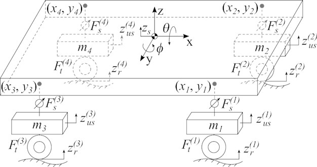
In Fig. 1, the designations correspond to: M, Ix and Iy sprung mass and moments of inertia along the longitudinal and transverse axes, respectively; z(i)us(i=1,2,3,4) – movement of unsprung masses; mi – unsprung masses; F(i)s– forces produced by the suspension supports; F(i)t – forces produced by the tires; zs, ϕ and θ – vertical movement, roll and pitch of the bodywork, respectively; (xi,yi) – points of attachment of the suspension supports to the bodywork.
The dynamics of the system is described by a system of nonlinear differential equations:
where:
and g is the acceleration of free fall.
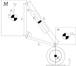
The kinematic scheme of a single active suspension support with a pneumohydraulic actuator is shown in Fig. 2(a), where Fc is the force produced by the hydraulic cylinder; l1, l2, l3are the geometric parameters of the suspension. The forces ˆFs produced by the ideal actuator are determined by the expression (to simplify the record, the index i is omitted):
Fig. 2Suspension support description
a) Kinematic scheme
b) Tire deformation
The length of the cylinder l3 is calculated based on the suspension geometry and the relative displacement of the suspension Δz=z-zus:
where the z-axis coordinate of the suspension mounting point is defined as:
In [12], the force produced by the hydraulic cylinder is defined as:
where pc is the pressure in the hydraulic cylinder; Ac is the area of the piston; η is the kinematic viscosity of the hydraulic fluid; sc is the movement of the piston associated with the movement of the suspension elements by the expression:
The pressure change in the hydraulic cylinder is described by a nonlinear differential equation [13]:
where β is the modulus of elasticity; V0 is the minimum volume of liquid in the cylinder cavity; u is the control flow of liquid; qa is the flow of liquid through a small hole connecting the hydraulic cylinder and the pneumatic accumulator:
where c is the coefficient of resistance to the flow; A is the area of the hole; ρ is the density of the hydraulic fluid; pcr is the minimum pressure of the turbulent flow; Δp=pa-pc is pressure drop; pa is pressure in the hydraulic accumulator [13]:
where k is the adiabatic index; ppr is the initial charge of the battery; VT is the volume of the battery. Assuming that the tire is deformed in only one direction the reaction force of the tire can be defined as:
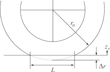
where W is the width of the tire; b is the damping coefficient; L is the length of the contact spot of the tire with the road surface; Δr=zr-zus. The length of the contact spot in accordance with Fig. 2(b) is calculated by the formula:
where rn is the nominal radius of the bus. Assuming that tire deformation is an adiabatic process, it can be determined that the tire pressure changes according to the equation:
where pn is the pressure in the unloaded tire:
These expressions are given for the ideal actuator, while the real actuator in its structure has a dead zone or (and) hysteresis. The force produced by the real one is denoted as Fs. The input exposure is indicated as ˆFs. In [13, 14], the actuator output in the presence of hysteresis is given by the equation:
where γ, n, α are the positive coefficients that determine the shape and width of the hysteresis loop; μ1>0, μ2>0 are the stiffness coefficients. The coefficients appearing in Eq. (16) can only be estimated approximately, and moreover, they change during the operation of the system, which significantly complicates the synthesis of an accurate observer.
3. Synthesis of a hierarchical discontinuous control system
Synergetic control theory uses modern ideas of mathematics and synergetics to synthesize nonlinear control laws for complex technical objects. Within the framework of the synergetic control theory, an analytical procedure for creating control laws for nonlinear, multi-connected, multidimensional systems has been developed. In the procedure of synthesis of control laws by the method of analytical design of aggregated regulators (ADAR) [11] the set of control goals is expressed as a system of invariants. The invariants reflect technological tasks and ensure the maintenance of intra-system (energy or structural) relations. The procedure of synergetic synthesis is about the construction of control laws that guarantee the fulfillment of the target set of invariants. At the first stage of the synthesis, it is necessary to define subsets of the goals of the lower level of the hierarchical control system (executive level) [15]. The system of the executive level of the active suspension is represented by a set of pneumohydraulic supports. The main technological task of the lower level of abstraction is the development of a given effort:
where Fr is the requested force. It should be noted that at this level, the effort developed by the ideal drive is purposefully used, since correct accounting of imperfections is associated with significant difficulties, and the results obtained lose relevance quickly. Along with the technological invariants, the subset of control objectives for each support must include kinematic constraints that are determined by the design features of the drive. In the case of hydraulic suspension, this constraint is the displacement of the hydraulic cylinder piston: |sc|≤smaxc. Let us make a macro variable using the equations:
where a is a positive constant that determines the rigidity of the constraint. This parameter determines the balance between performing a technological task and maintaining kinematic constraints. According to the ADAR method, the macro variable yields the solution ψ(i)L=0 of the functional equation:
where T(i)Lis a positive constant that determines the rate of convergence of the image point of the system with the invariant manifold. The solution of Eq. (17) with the use of the equations of the ideal actuator with respect to u gives the control law that ensures the implementation of the technological task taking into account the kinematic constraints in the system.
The next stage is the synthesis of control laws for the upper level of the hierarchy. The main technological task of the upper level of the suspension control is to isolate the car bodywork from shocks and vibrations caused by road surface bumps. The technological task of a fully active suspension is broader: to keep the position and orientation of the car bodywork in a given position:
where zr is a given position of the car bodywork; ϕr, θr are given orientation angles. Following the procedure of the ADAR method, let us form a set of macro variables that reflect the task of the upper level of abstraction Eq. (18):
The control laws uz, uθ, uϕ are the solution of a system of differential equations:
where λi(i=¯1,6) are the constants that ensure the stability of the system Eq. (21). The solution of the system Eq. (20) is:
However, for the lower level of abstraction, it is necessary to determine the required forces for each of the supports Fr , so it is necessary to solve the system of Eqs. (2), (16), (22) relative to Fr. The peculiarity is that there are three equations and four unknowns. The most common solution to this problem is to introduce an additional equation:
which is to eliminate the influence of the rear shock absorbers on the roll of the bodywork.
4. Stability research
To prove stability it is necessary to determine the conditions for getting the system into the neighborhood of the intersection of the given invariant manifolds. The occurrence of a sliding mode on the switching surface is a condition for the system of the lower level of the hierarchy:
For the occurrence of a sliding mode, it is necessary that the condition s⋅˙s<0 is met for any s≠0. Substituting Eq. (24) into Eq. (17) from Eq. (18) we can find ˙s:
Thus, the condition for the occurrence of a sliding mode can be rewritten in the form -s2/T(i)L<0 that is obviously fulfilled for any s≠0under the condition T(i)L>0.
For a stable approach to the switching surface, it is necessary to guarantee the stability of the functional Eq. (18). It is obvious that the Eq. (18) is stable under T(i)L>0. Thus, the choice T(i)L>0 guarantees the convergence of the system with the switching surface and stable movement on it.
The stability of the solution of the system of functional equations (20) provides a guaranteed convergence of a closed system with the intersection of invariant manifolds ψz=0∩ψθ=0∩ψφ=0. Having determined the conditions for the system to fall into the neighborhood of the intersection of the given invariant manifolds, it is necessary to determine the stability of movement along the intersection of the manifolds. In accordance with the synergetic principle of “expansion-contraction of the phase space” [11], when a controlled system enters the neighborhood of the intersection of manifolds, a dynamic decomposition occurs in it. As a result of which the behavior of the system in the neighborhood of this intersection of manifolds can be described by a decomposed model. In particular, when considering the upper level of the hierarchy, this model is obtained by excluding a number of differential equations from the original model Eq. (1) due to the introduced invariant manifolds ψz=0, ψϕ=0, ψθ=0 and the relations˙ψz=0, ˙ψϕ=0, ˙ψθ=0. Thus, the order of the decomposed model will be six less than the order of the original model, which determines the zero order of the decomposed system. As a result of such a decomposition, the upper level of the hierarchy undergoes a complete decomposition and the behavior of the system at the intersection of manifolds is completely determined by the following relations ψz=0, ψϕ=0, ψθ=0, ˙ψz=0, ˙ψϕ=0, ˙ψθ=0, and therefore the stability of the upper level is completely determined by Eqs. (21).
To compile a decomposed model of the lower level of the hierarchy, we express a variable pc from the equation s=0 and substitute the resulting solution in the right parts of Eqs. (1), (10). The result of this operation is a system of differential equations:
where
f3=p(i)a-(F(i)r-f2)f1(l22+(z(i)us)2)2l1l42(-l1z(i)us+(l22+l21-l222)√1+(z(i)us)2l22)-ηl1v(i)us(1+(z(i)us)2l22)32√f1Ac,
f4=√-2rnz(i)us-(z(i)us)2.
To prove the stability of the system Eq. (26), we use Lyapunov’s theorem on stability in the first approximation. Considering the system parameters presented in Table 1, we find the equilibrium point of the system Eq. (25) under the condition that there are no external disturbances:
The Jacobian of the system Eq. (26) at the equilibrium point Eq. (27) has the form:
The eigenvalues of the Jacobian Eq. (28) are: p1= –1.45271×10⁻⁷; p2= –244.9874338; p3 = –755.0125660. Since the real part of all eigenvalues is negative according to Lyapunov's theorem on stability in the first approximation, it can be argued that the only equilibrium state of the system Eq. (26) is asymptotically stable.
5. Closed system research
To study the proposed control system for the active suspension of the car, numerical simulation of the system in the Simulink environment is used. The road surface model uses white noise with a limited band:
where T=1/2πf; f= 30 Hz; ξ is white noise with a variance of σ2 and zero mathematical expectation. The parameters of the vehicle suspension model and the control system under study are presented in Table 1 [16].
Table 1Closed system parameters
Parameter | Value | Parameter | Value | Parameter | Value |
M | 1750.5 | Ix | 550 | λ1=λ3=λ5 | 10 |
Iy | 1848 | x1=x2 | 1.0 | ν | 0.35 |
x3=x4 | –1.4 | y1=y4 | –0.6 | ϕr | 0 |
y2=y3 | 0.8 | l(i)1 | 0.2 | λ2=λ4=λ6 | 25 |
l(i)2 | 0.2 | smaxc | 0.04 | zr | 0 |
mi | 50 | W | 0.175 | θr | 0 |
rn | 0.295 | pn | 130·103 | c | 0.7 |
Vn | 0.03288 | b | 1000 | V0 | 72.83·10-6 |
Ac | 1.256·10-3 | β | 2·109 | A | 2e-9 |
ρ | 870 | VT | 0.4 | ppr | 4.5·106 |
To assess the efficiency of the closed system, the standard-square acceleration of the bodywork is used [1], which also reflects the level of passenger comfort. In this paper, we study the vertical acceleration and the total angular acceleration of the bodywork calculated as ¨a(t)=√¨θ2(t)+¨ϕ2(t). The object of comparison is a similar active suspension system, but with an adaptive regulator [16], as well as a passive shock absorption system, which can be obtained from the current model by assuming that u(i)=0. To demonstrate the differences better, all estimates are relative. The passive depreciation system is chosen as the base system, so the following two metrics are used to analyze the effectiveness:
where ()*means the signal of the reference (passive) system.
Fig. 3Bodywork vertical acceleration
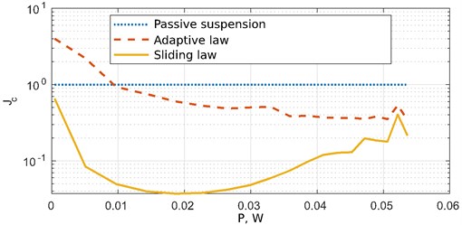
Fig. 4Bodywork angular acceleration
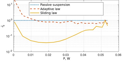
Figs. 3 and 4 show graphs of the efficiency metrics obtained from the vertical and angular acceleration signals of the bodywork, respectively.
Having studied the results of the calculation it can be concluded that the adaptive control system of the active suspension has a high sensitivity to changes in the parameters of the actuator. It also shows less efficiency than the passive suspension in the area of small disturbances (power less than 0.1 W). When exposed to a disturbance with a power of more than 0.01 W, the efficiency of the active suspension with an adaptive law increases and exceeds the passive system. If the proposed discontinuous control system is used, the active suspension provides better comfort (compared to the passive system) in the entire study area. Proposed control law allows decreasing vertical and angular acceleration of the car body in case of unknown nonlinearities in the control object and kinematic constraints.
6. Conclusions
This paper proposes a synergetic law of discontinuous control of the active suspension system of the car. The peculiarity of the proposed control law is that it takes into account the design limitations of the executive mechanism, and low sensitivity to structural changes in the parameters of the control object. The efficiency of the proposed system is investigated by numerical simulation of a closed system in the Simulink environment. The results of numerical simulation clearly demonstrate that the application of the synergetic control theory in the synthesis of discontinuous control systems allows expanding the effectiveness of the suspension more than 4 times in comparison with the adaptive law.
References
-
K. Bayar and F.-S. Khaneghah, “Optimal sliding mode control method for active suspension control,” IFAC-PapersOnLine, Vol. 53, No. 2, pp. 14285–14291, 2020, https://doi.org/10.1016/j.ifacol.2020.12.1178
-
X. Dang, X. Zhao, C. Dang, H. Jiang, X. Wu, and L. Zha, “Incomplete differentiation-based improved adaptive backstepping integral sliding mode control for position control of hydraulic system,” ISA Transactions, Vol. 109, pp. 199–217, Mar. 2021, https://doi.org/10.1016/j.isatra.2020.10.027
-
C. M. Ho, D. T. Tran, and K. K. Ahn, “Adaptive sliding mode control based nonlinear disturbance observer for active suspension with pneumatic spring,” Journal of Sound and Vibration, Vol. 509, p. 116241, Sep. 2021, https://doi.org/10.1016/j.jsv.2021.116241
-
F. Zhao, S. S. Ge, F. Tu, Y. Qin, and M. Dong, “Adaptive neural network control for active suspension system with actuator saturation,” IET Control Theory and Applications, Vol. 10, No. 14, pp. 1696–1705, Sep. 2016, https://doi.org/10.1049/iet-cta.2015.1317
-
W. Jue and Z. Jing, “Model-free tracking control for vehicle active suspension systems,” in 34th Chinese Control Conference, pp. 1696–1705, 2015.
-
V. S. Deshpande, P. D. Shendge, and S. B. Phadke, “Dual objective active suspension system based on a novel nonlinear disturbance compensator,” Vehicle System Dynamics, Vol. 54, No. 9, pp. 1269–1290, Sep. 2016, https://doi.org/10.1080/00423114.2016.1198490
-
D. Recker, P. Kokotovic, D. Rhode, and J. Winkelman, “Model-free tracking control for vehicle active suspension systems,” in 4th International Conference on Intelligent Control and Information Processing, pp. 59–63, 2013.
-
J. Dong and B. Mo, “The adaptive PID controller design for motor control system with backlash,” in 2013 Fourth International Conference on Intelligent Control and Information Processing (ICICIP), pp. 59–63, Jun. 2013, https://doi.org/10.1109/icicip.2013.6568040
-
T. Chang, D. Yuan, and H. Hanek, “Matched feedforward/model reference control of a high precision robot with dead-zone,” IEEE Transactions on Control Systems Technology, Vol. 16, No. 1, pp. 94–102, Jan. 2008, https://doi.org/10.1109/tcst.2007.899733
-
A. N. Danilin and A. D. Shalashilin, “Hysteresis modelling of mechanical systems at nonstationary vibrations,” Mathematical Problems in Engineering, Vol. 2018, No. 1, pp. 1–15, 2018, https://doi.org/10.1155/2018/7102796
-
A. A. Kolesnikov, Synergetic Control Theory. (in Russian), Moscow, Russia: Energoatomizdat, 1994.
-
A. Ylinen, H. Marjamäki, and J. Mäkinen, “A hydraulic cylinder model for multibody simulations,” Computers and Structures, Vol. 138, pp. 62–72, Jul. 2014, https://doi.org/10.1016/j.compstruc.2014.02.006
-
F. Korkmaz, Hydrospeicher als Energiespeiche. (in German), Berlin, Germany: Springer-Verlag, 1982.
-
U. S. Pusadkar, S. D. Chaudhari, P. D. Shendge, and S. B. Phadke, “Linear disturbance observer based sliding mode control for active suspension systems with non-ideal actuator,” Journal of Sound and Vibration, Vol. 442, pp. 428–444, Mar. 2019, https://doi.org/10.1016/j.jsv.2018.11.003
-
G. Veselov, “Nonlinear complex system’s hierarchical control strategies synthesis tasks,” in 3rd Chaotic Modeling and Simulation International Conference, 2010.
-
G. Veselov and A. Sinicyn, “Synthesis of nonlinear control law for car hydraulic suspension with regard kinematic constraints,” in 2019 12th International Conference on Developments in eSystems Engineering (DeSE), pp. 704–708, Oct. 2019, https://doi.org/10.1109/dese.2019.00131

