Abstract
For seismic analysis of wide structures (for example, airports, stadiums, bridges, etc.), it is important to consider the wave seismic motion of the ground with spatial variability. The differential seismic motion is described by the vector field of kinematic parameters at each point of the base. The differential model of seismic excitation is used for structures on a flexible foundation or discrete supports, if the short-length waves (compared to the size of the foundation) are dominated in seismic waves spectrum. Such excitation is accompanied by angular displacements due to uneven translational ground motions, and it is not yet possible to consider using standard seismic analysis. This paper presents a method of differential seismic analysis with the corresponding modification of the response spectrum (RSM) method. The proposed method requires three accelerograms at each reference point. These accelerograms can be obtained during detailed seismic zoning. To illustrate the method, a model of a stadium cover is considered, for which it is important to apply a spatial differential seismic excitation, and some properties of the excitation are described and analyzed.
1. Introduction
The data from seismic arrays can show significant spatial variability of the seismic ground motion within small sites [1, 2]. The spatial variability can be considered in the earthquake-resistant design on the base of differential models of ground motion, with estimating seismic loads and obtaining seismic response by Response Spectrum Method (RSM) [3-6].
This paper presents a new modal approach to the seismic analysis of extended structures, when the spatial nature of the seismic excitation is taken into account. It includes a description of spatial differential motion for structural seismic analysis and calculation of seismic response of a structure using the RSM.
2. Differential seismic excitation
The differential seismic excitation is transferred to a structure as kinematic excitation of the ground base. The ground motion at the support points can be described three translational displacements. For structure with p support points the ground motion at the ith point (x1i,x2i,x3i) is described by the vectors of absolute translational displacements, velocities, and acceleration Xi(t,x1i,x2i,x3i)=(X1iX2iX3i)T,˙Xi(t,x1i,x2i,x3i)=(˙X1i˙X2i˙X3i)T,¨Xi(t,x1i,x2i,x3i)=(¨X1i¨X2i¨X3i)T, i=1,...,p. The vector of translational accelerations at the ith point is equal to:
where |¨Xi|=√(¨X1i)2+(¨X2i)2+(¨X3i)2 – its magnitude, νi(t)=(ν1iν2iν3i)T – the vector of the directional cosines ν1i=¨X1i/|¨Xi|, ν2i=¨X2i/|¨Xi|, ν3i=¨X3i/|¨Xi|.
Peak translational accelerations at the ith point are equal to Ii=max|¨Xi|. For the modal RSM the vector ¨Xi and directional cosines of the seismic excitation are considered as constant:
The directions νi are found from maximum of the dynamic structural response and known as critical directions of the seismic excitation. The directions of the seismic loads applied to the structure are determined solely from its dynamic properties.
Spatial kinematic parameters at the different points is expressed in terms of the same parameters at the anchor point, for example, at the first point with displacements X1 and accelerations ¨X1. According to Eq. (2), at the first point the accelerations are expressed in terms of the peak translational acceleration I=I1 and directional cosines ν1: ¨X1(x1,x2,x3)=Iν1.
For the spatial kinematic field of accelerations, scalar matrix functions of coordinates are introduced. At the ith point with coordinates ri=(x1i,x2i,x3i):
Τ1i=Iiν1i/(I1ν11),Τ2i=Iiν2i/(I1ν21),Τ3i=Iiν3i/(I1ν31).
Then three-dimensional vector of accelerations at the ith support point is written via peak acceleration at the anchor point (with regard to ¨Xi=Ii⋅νi) ¨Xi=Τi¨X1=IΤiν1.
The 3p dimensional vector of accelerations ¨X is equal to:
Amplification factors (AFs) can be different at different points of the spatial kinematic field. The ground motion at the ith support point is described by three-dimensional vector of spectral AFs βi(Ω)=(β1iβ2iβ3i)T. At the anchor point β1(Ω)=(β1β2β3)T, where Ω is the natural frequency.
Functions Θji are introduced for describing of spatial spectral variation of seismic excitation (j – the number of the accelerations vector component ¨Xi, j=1,2,3; i – the number of the support point, i=1,...,p). At the ith -support point with ri=(x1i,x2i,x3i) the AFs are equal:
or in matrix form βi(Ω,ri)=Θi(Ω,ri)β1(Ω), where Θ[3×3]i=diag(Θ1i,Θ2i,Θ3i) – the matrix of spatial spectral functions relatively to the anchor point. All AFs at all support points are given by the vector β: β[3p]=β(Ω)=(β1...βp)T. Introduce the matrix of the spatial spectral functions Θ[3p×3]=(Θ1,Θ2,...,Θp)T, then the AFs at all support points are expressed about the anchor point β[3]1: β=Θβ1.
3. Equations of motion
Consider a structure with n degrees of freedom under multidimensional kinematic excitation transferred to the structure through p support points. Denote q[n]abs – the vector of absolute generalized displacements, q[n] – the vector of relative generalized displacements, q[n]tr – the vector of transport motion and:
The transport motion qtr is defined as displacements caused by the displacements X of all support points. Equations of absolute motion of the structure are:
where M[n×n], B[n×n] and K[n×n] – the mass, damping and stiffness matrices, K[n×3p]s, B[n×3p]s– the stiffness and damping matrices of support elements, X[3p] and ˙X[3p] – the vectors of displacements and velocities of the ground at support points. From the equilibrium of the structure at the support points (˙q[n]tr – the vector of transport velocities):
Substituting Eq. (4) in Eq. (5) and considering Eq. (6) we get the equation of the relative motion:
For the case of small damping Kqtr+KsX≫B˙qtr+Bs˙X, therefore from Eq. (6) Kqtr+KsX=0. Denote the flexibility matrix F=K-1, then the transport motion vector is qtr=-FKsX, and the equation of relative motion Eq. (7) has the form:
Denote the matrix of the transport inertial coefficients M[n×3p]s=-MFKs, then Eq. (6) takes the ordinary form of the relative motion equation:
4. Structural seismic response
For solution of Eq. (8) is used modal analysis with orthogonal transformation q=Vu, where u – the vector of normal coordinates, V – the matrix of modes vk, k=1,2,...,n. Eq. (8) about normal coordinates is:
where Ω2 is the matrix of squares of natural frequencies, Q=-M-1modVTMs¨X – the vector of transport seismic forces. Considering Eq. (3), Q=-IM-1modVTMsΤν, Mmod=VTMV.
From Eq. (9) static modal displacement is ustk=-IMmod,kΩ2kvTkMsTνk, where νk – the vector of critical directions of seismic excitation for the kth mode, Mmod,k=vTkMvk – the modal mass for the kth mode. Dynamic modal displacements for the kth mode is obtained as a product of ustk and βk: uk=-βkIMmod,kΩ2kvTkMsTνk.
Structural seismic response S can be decompose by the sum of modal responses Sk:
S=Kq=∑nk=1ukKvk=∑nk=1ukΩ2kMvk=∑nk=1Sk, where Sk=ukΩ2kMvk – the vector of modal response corresponding to the kth mode. If m[n]i(i=1,...,n) is the ith row of the mass matrix M, and ith element of Sk is Sik=βkImivkvTkMsMmod,kTνk.
5. Research and testing
To test the method, we perform calculations of many types of structures, both very simple [4, 5] and real complex models of structures under various types of earthquakes.
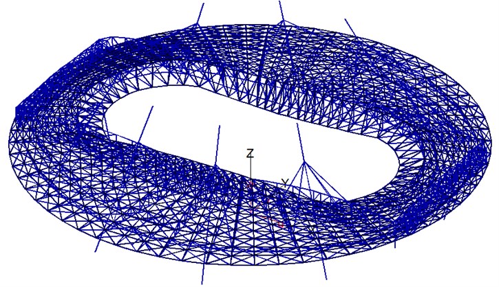
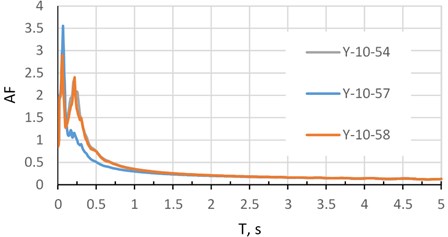
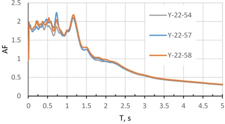
A good example for studying the effect of spatial seismic variability on the dynamic response is a stadium cover model in Fig. 1, which has 8 main supports arranged in a circle with a diameter of 250 m. The range of natural frequencies taken for seismic analysis is 0.13-1.45 Hz, in natural periods 0.7-7.7 s. The ground accelerations at each support are different. To determine the differential ground motion, we have records of two weak natural earthquakes recorded at one of industrial sites [7] at points with distances between them of 150-200 m. A soil is composed of sand and clay layers. A shear waves velocity at near-surface is 230-300 m/s. A seismic event No. 10 is local, short and more high-frequency; an event No. 22 is regional, long and more low-frequency. In Fig. 2 and 3 are shown the amplification factors (AF) of both earthquakes depending on natural periods T for one of horizontal components (direction Y).
Fig. 1Finite element model of the stadium cover

Table 1 shows the standard deviations (SD) of accelerations for both events for each of the three directions at points 54, 57, and 58. These points are located on a flat site at the vertices of an almost equilateral triangle with sides of about 175 m.
Table 1Standard deviation (SD) of accelerations
N | Earthquake | Point | SD X, m/s2 | SD Y, m/s2 | SD Z, m/s2 |
1 | No.10 | 54 | 0.124451 | 0.088494 | 0.081404 |
2 | No.10 | 57 | 0.123765 | 0.083774 | 0.103234 |
3 | No.10 | 58 | 0.108314 | 0.070068 | 0.089063 |
14.9 % | 26.2 % | 26.8 % | |||
4 | No.22 | 54 | 0.046274 | 0.048406 | 0.026092 |
5 | No.22 | 57 | 0.037831 | 0.039813 | 0.02512 |
6 | No.22 | 58 | 0.049908 | 0.042103 | 0.022043 |
31.9 % | 21.6 % | 18.4 % | |||
Both events demonstrate a significant variability of the acceleration field, more expected for a short-wave event No. 10. In Table 1 the difference between the maximum and minimum SD reaches almost 27 % for event No. 10 and almost 32 % for event No. 22; it indicates the need to apply seismic analysis based on a differential model of ground motion.
Usually, an earthquake engineering of many wide structures is assumed identical ground motion at all support points and using only one accelerogram. Comparing the seismic loads calculated in the traditional way with the loads obtained by the proposed method, we can make brief conclusions: spatial seismic impact leads to a different distribution of seismic loads and internal forces, to a significant increase of seismic loads on some structural elements, to other mechanisms of damage accumulation and destruction.
Fig. 2Amplification factors. Earthquake 10 at points 54, 57, 58, direction Y

Fig. 3Amplification factors. Earthquake 22 at points 54, 57, 58, direction Y

6. Conclusions
The paper presents modified RSM that is applied for differential seismic analysis of structures. This method works reliably for random unpredictable wave processes at the base, considering the worst possible situations, for example, the motion of different supports in opposite phases.
Currently, the proposed method is being tested on real large complex objects, a dependence between structural response and variability of spatial seismic ground motion is investigated, new software is developed and put into practice.
The results of this work can be applied in new seismic standards.
References
-
Liu C., Huang B., Lee W. H. K. Observing rotational and translational ground motions at the HGSD station in Taiwan from 2007 to 2008. Bulletin of the Seismological Society of America, Vol. 99, 2009, p. 1228-1236.
-
Yin J., Nigbor R. L., Chen Q., Steidl J. Engineering analysis of measured rotational ground motions at GVDA. Soil Dynamics and Earthquake Engineering, Vol. 87, 2016, p. 125-137.
-
Nazarov Y. P. The Analytical Calculation Fundamentals of Constructions on Seismic Loads. Nauka, Moscow, 2010, (in Russian).
-
Nazarov Y. P., Poznyak E. V. Response spectrum method for integrated and differential spatial seismic ground motions. Soil Dynamics and Earthquake Engineering, Vol. 108, 2018, p. 69-78.
-
Poznyak E. V. The application of the generalized response spectral method. Part 2. Differential seismic impact. Structural Mechanics and Analysis of Constructions, Vol. 4, 2018, p. 61-68, (in Russian).
-
Nazarov Y. P., Poznyak E. V. Spatial variability of seismic-ground movements in structure analysis. Soil Mechanics and Foundation Engineering, Vol. 51, Issues 5, 2014, p. 242-247.
-
Bugaevsky G. N., Bugaevsky A. G. Seismic spectral-dynamic zoning of sites and constructions. Budivelni Konstruksii, Vol. 53, Issue 1, 2000, p. 69-77, (in Russian).

