Abstract
A finite element model is established to study the settlement control technology of the ballastless track of high-speed railway under the shield of shallow buried tunnel. In particular, the reinforcement mechanism and construction control technology of the Metro Jet System (MJS) method for horizontal reinforcement under complex geological conditions (medium coarse sand and strong permeable layer) are discussed. The results showed that when the ground is not reinforced, the shield tunnel directly passes through the high-speed railway, and the settlement caused by the construction of the railway gene tunnel directly above the tunnel has greatly exceeded the limit of the settlement control standard. Due to the limitations of site, planning and construction conditions, the horizontal jet grouting pile of MJS construction method is selected as an auxiliary measure through comprehensive comparison. After the completion of the MJS construction, the maximum settlement of the subgrade is 30 mm, and the settlement of the high-speed railway subgrade is about 25 mm.
Highlights
- A finite element model is established to study the settlement control technology
- Metro Jet System method for horizontal reinforcement under complex geological conditions are discussed
- Embankment deformation of shield crossing high-speed railway under reinforced and unreinforced conditions is compared
1. Introduction
As the core technology of underground space development, shield tunneling technology has been widely used in the fields of energy and transportation tunnel construction. Although it has many advantages of shield construction, and in the development of more than one hundred years of shield machine performance is improved, but due to the construction of ground movement, in turn, affects the surface structure of hazards and accidents still happen. If the characteristics of the surrounding strata cannot be accurately predicted and the deformation characteristics of the soil around the tunnel cannot be obtained in the process of tunnel tunneling, the construction may cause great damage to the surface structure of the tunnel. Especially when the subway tunnel needs to run under the high-speed railway with a maximum speed of 350 km/h. It is very important and of practical significance to study settlement control measures to ensure the safety of important facilities such as high-speed railway in construction area.
There are few projects of tunnel underpass high-speed railway, which mainly focus on the theoretical analysis level. Zhang et al. [1] made a detailed analysis of the causes and solutions of the ground displacement caused by the underpassing of three-pipe shield tunnel, which provided a reference for the construction of similar projects. Tao et al. [2] compared and studied the reinforcement scheme of the railway subgrade under the shield, and got a better supporting effect. Chen et al. [3] studied the construction scheme and reinforcement measures of shield tunnel under the existing railway in the weak stratum. Huang et al. [4] proposed an accurate method for prediction of the stability of rock surrounding a tunnel.
High-speed railway has almost instantaneous requirements for subgrade deformation, so the study and control of subgrade deformation law is very important and extremely practical value. In this paper, a finite element model is established to study the settlement control technology of the ballastless track of high-speed railway under the shield of shallow buried tunnel. In particular, the reinforcement mechanism and construction control technology of the Metro Jet System (MJS) method for horizontal reinforcement under complex geological conditions (medium coarse sand and strong permeable layer) are discussed. It is the first engineering application of the new technology of MJS horizontal reinforcement operation of high-speed railway subgrade in China, and it is also the deepest horizontal reinforcement project of MJS in China. The results can provide reference for similar projects.
2. Finite element model
According to the general situation of the project, the strata range is selected as follows: 2.5 times the diameter of the tunnel on the left and right sides of the tunnel structure, that is, 15 m. Take about 2.5 times the hole diameter below the bottom plate of the interval structure, that is, 15 m. The length of the shield tunnel segment is 1.5 m. The length of the tunnel excavation direction is an integer multiple of the segment ring, which is 120 m. Model dimension is 50×120×30 m. The Angle between track plate and shield tunnel of Beijing-Guangzhou high-speed railway is 70°, the distance between two crossing lines is 5 m, and the distance between crossing lines and arrival and departure lines is 6.5 m. A total of 4 Wuhan-Guangzhou railway ballastless track board and supporting layer is built into a layer with the width of 2.8 m and thickness of 0.5 m. The thickness of gravel layer is 0.5 m. The lower part of the gravel layer is followed by artificial filling soil layer, silty clay layer, medium coarse sand layer, silty clay layer and stable bedrock.
The surrounding rock is assumed to be an ideal elastoplastic material and obey the Mohr-Coulomb yield criterion. The element types are all 8-node hexahedral three-dimensional solid elements and 4-node tetrahedral three-dimensional solid elements, and a total of 157991 solid elements are divided. The established numerical model is shown in Fig. 1.
Fig. 1Finite element model
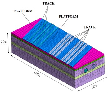
Table 1Physical and mechanical parameters of surrounding rock
Layers | Thickness (m) | Density (Kg/m3) | Compression modulus (MPa) | Poisson’s ratio | Friction angle (°) | Cohesion (kPa) | Tensile strength (kPa) |
Artificial filled soil | 2.4 | 1910 | 7.4 | 0.42 | 15 | 18 | 12 |
Plastic silty clay | 1.8 | 1940 | 6.1 | 0.32 | 22.4 | 21.7 | 14 |
In the thick sand layer | 9 | 2050 | 6 | 0.26 | 33 | 0 | 0 |
Hard plastic powder clay | 3.8 | 2000 | 7.2 | 0.26 | 30 | 29.9 | 20 |
Limestone breezes | 13 | 2750 | 28.5 | 0.15 | 29 | 600 | 400 |
The following boundary conditions are selected: the plane X=0 and X=50 are used to limit its displacement in the X direction. The plane Y=0 and Y=120 constrains its displacement in the Y direction. The plane Z= –30 limits its displacement in X, Y, and Z directions. Design load of high speed railway subgrade is set as 64.48 kPa.
The stratigraphic division, physical and mechanical parameters of the strata and shield structure parameters in the numerical model are shown in Table 1 and Table 2.
Table 2Shield structure parameters
Material | Modulus of elasticity (MPa) | Poisson’s ratio |
Shield shell | 206000 | 0.30 |
Segment | 34500 | 0.25 |
Grouting layer after solidification | 150 | 0.25 |
3. Analysis of deformation caused by shield excavation in unreinforced stratum
Fig. 2 shows the ground subsidence surface and isolines after the completion of two tunnels. It can be seen from the figure that the surface settlement value of the middle line of the double-track tunnel is the largest, with the maximum surface settlement value of 66 mm. The maximum surface settlement at the location of the high-speed railway subgrade is about 59 mm.
Fig. 2Ground subsidence surface and isolines
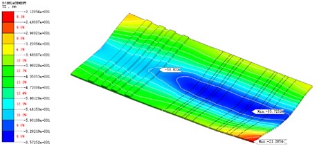
Fig. 3Subgrade settlement groove curve
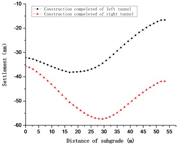
Fig. 3 shows the settlement groove curve of the subgrade when the left tunnel and right tunnel construction is completed without reinforcement of the stratum. It can be seen from the figure that the settlement caused by the construction of the railway gene tunnel directly above the tunnel has exceeded the limit of the settlement control standard of 10 mm. When the left tunnel is through, the maximum settlement of the high-speed railway subgrade occurs above the left tunnel. After the construction of both tunnels, the maximum settlement of the high-speed railway subgrade is located on the symmetry plane of the two tunnels. The position of the maximum settlement of high-speed railway changes before and after the left and right lines are completed, and the maximum settlement value increases.
The excavation of shield tunnel causes the settlement of ground surface and roadbed, and the track on roadbed subsided. Because the absolute settlement of the two tracks is different, the differential settlement will occur between the two tracks. If the differential settlement is too large, it will affect the safety of railway operation. According to the calculation results, the maximum differential settlement of 1# track (Fig. 4) is 0.7 mm, that of 2# track is 0.5 mm, that of 3# track is 0.5 mm, and that of 4# track is 0.6 mm under the condition without strata reinforcement. The differential settlement of tracks did not exceed the settlement limit of 2 mm.
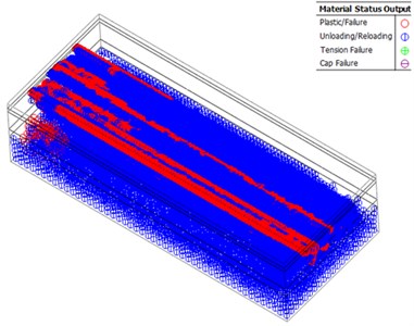
Fig. 5 shows the plastic separation layout after the completion of double-line shield construction when the stratum is not reinforced. As can be seen from the figure, because the shield tunnel is in the sand layer, the shear failure zone will be generated. Around the tunnel, due to the influence of excavation disturbance, shear failure of different degrees will also occur. However, due to the supporting effect of shield shell and the timely installation of segments, the range of shear failure zone caused by shield excavation is limited.
Fig. 4High-speed railway track location diagram
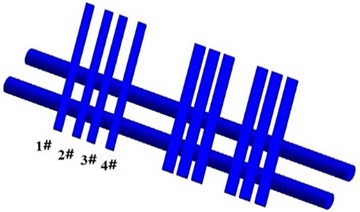
Fig. 5Plastic separation layout after completion of double-line shield construction
4. Influence of MJS reinforcement method on subgrade settlement of high-speed railway
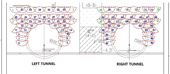
MJS horizontal rotary jet grouting piles were used to reinforce the stratum. The rotary jet grouting range is 170° in the lower semicircular, the effective improved body diameter is 2.0 m, the transverse pile spacing is 1.7 m, the occlusion is 0.3 m, the vertical spacing is 0.7 m, and the occlusion is 0.3 m. Jet pressure of cured material 40 Mpa, and air pressure of cured material discharge 0.7 MPa. The layout scheme is shown in Fig. 6.
Fig. 6Jetting pile layout drawing
According to Fig. 7, due to the formation disturbance caused by MJS construction, the vertical displacement of soil layer in a certain range directly above the area where the jet grouting pile is located is large. After the completion of the MJS construction, the maximum settlement of the subgrade is 30 mm, and the settlement of the high-speed railway subgrade is about 25 mm.
Fig. 7Subgrade settlement surface and isoline after MJS Construction (Unit: mm)
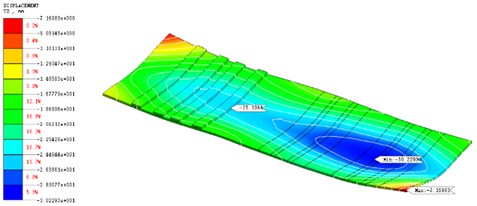
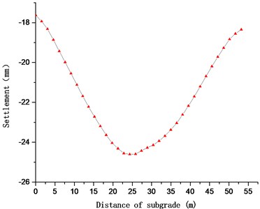
Fig. 8 shows the subgrade settling groove curve after the completion of MJS construction. The maximum settlement of high-speed railway subgrade occurs directly above the construction of MJS jet grouting pile, and the maximum settlement value is about 25 mm.
Fig. 8Subgrade settling groove curve after completion of MJS construction
According to the calculation results, the maximum differential settlement of 1# track from Fig. 4 is 0.8 mm, that of 2# track is 0.6 mm, that of 3# track is 0.2 mm and that of 4# track is 0.3 mm. The differential settlement of tracks did not exceed the settlement limit of 2 mm.
Fig. 9MJS spray construction after the completion of plastic differentiation layout
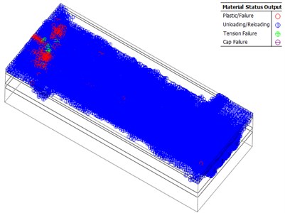
Fig. 9 shows the plastic separation layout after the completion of MJS rotary spray construction. It can be seen from the figure that around MJS jet grouting pile, due to the influence of construction disturbance, shear failure of different degrees will occur, but the range of shear failure is relatively small.
From the above analysis, it can be seen that the ground subsidence value generated by the shield tunneling without stratum reinforcement is much larger than the allowable value, about 60mm, which cannot meet the safe operation of the train. Therefore, the auxiliary reinforcement measures of stratum must be taken.
In the actual construction of this project, MJS horizontal rotary jet injection is used to reinforce the stratum, and the simulated settlement value is about 30 mm. Compared with the direct shield tunneling without reinforcement, the settlement value of high railway foundation is reduced by about 50 %. Although it still fails to meet the limit requirements, in the process of MJS construction, the settlement magnitude of ballastless track caused by the construction of each MJS horizontal jet grouting pile is small, and the settlement amount caused by the crossing of the reinforced backing structure is also small. The settlement of the whole construction process is slow and controllable, so in the construction process, we can ensure the safety of high-speed railway operation by means of speed limit, fine adjustment and lifting.
5. Conclusions
In this paper, the numerical simulation analysis of tunnel construction under high-speed railway is carried out, and the embankment deformation of shield crossing high-speed railway under reinforced and unreinforced conditions is compared in detail, and the following conclusions are drawn:
1) When the stratum is not reinforced, the surface settlement value of the middle line of the two-track tunnel is the largest, which is 66 mm, and the width of the surface settlement groove increases from 45 m when the original left line is through to about 60 m.
2) When the ground is not reinforced, the shield tunnel directly passes through the high-speed railway, and the settlement caused by the construction of the railway gene tunnel directly above the tunnel has greatly exceeded the limit of the settlement control standard. Due to the limitations of site, planning and construction conditions, the horizontal jet grouting pile of MJS construction method is selected as an auxiliary measure through comprehensive comparison.
3) After the completion of the MJS construction, the maximum settlement of the subgrade is 30 mm, and the settlement of the high-speed railway subgrade is about 25 mm.
References
-
Zhang X.,Zhou S., He C. Experimental investigation on train-induced vibration of the ground railway embankment and under-crossing subway tunnels. Transportation Geotechnics, Vol. 26, 2021, p. 100422.
-
Tao K., Zhang Y., Hou K. Experimental study on temperature distribution and smoke control in emergency rescue stations of a slope railway tunnel with semi-transverse ventilation. Tunnelling and Underground Space Technology, Vol. 106, 2020, p. 103616.
-
Cheng Y., Qiu W., Duan D. Automatic creation of as-is building information model from single-track railway tunnel point clouds. Automation in Construction, Vol. 106, 2019, p. 102911.
-
Huang S., Qi Q., Liu J., Liu W. Tunnel surrounding rock stability prediction using improved KNN algorithm. Journal of Vibroengineering, Vol. 22, Issue 7, 2020, p. 1674-1691.
