Abstract
To compare the friction power loss between the crankpin bearing (CPB) and crankshaft bearing (CSB) on improving the engine power, a slider-crank-mechanism dynamic model is established to compute the dynamic loads, Wp and Ws, impacting on the CPB and CSB. Based on the impact of Wp and Ws, a hydrodynamic lubrication model of the CPB and CSB is built to calculate the friction forces, Fp,s, and coefficient of frictions, μp,s, generated on the CPB and CSB. The simulation results of the Fp,s and μp,s on improving the engine power are then compared and analyzed, respectively. Under the same operation condition, the research results show that the friction power loss of the CPB is larger than that of the CSB under both the low and high engine speeds. Besides, the friction power loss of the CPB at 6000 rpm is also higher than that of 2000 rpm of the engine speed. Consequently, the friction power loss of the engine is greatly influenced by the crankpin bearing and at a high engine speed of 6000 rpm.
Highlights
- A slider-crank-mechanism dynamic model is established to compute the dynamic loads, Wp and Ws, impacting on the rod bearings of the engine.
- Under the same operation condition, the research results show that the friction power loss of crankpin bearing is larger than that of crankshaft bearing under both the low and high engine speeds.
- The friction power loss of crankpin bearing at 6000 rpm is also higher than that of 2000 rpm of the engine speed.
- The friction power loss of the engine is greatly influenced by the crankpin bearing and at a high engine speed of 6000 rpm.
1. Introduction
Engine power and fuel economy were the main concerns of the internal combustion engine manufacturers. To improve the engine power, the combustion mixture composition, combustion chamber pressure, engine cooling system which affected the engine power were studied [1, 2]. The results showed that the engine power and fuel economy ware significantly improved. However, the friction power loss was still quite high [3, 4]. The main causes were due to the piston skirt and ring against the cylinder bore, relative motion of the joints of the slider-crank mechanism (SCM), crankpin (CPB), and crankshaft bearings (CSB) [5, 7]. The design parameters and inertial forces of the SCM were investigated to reduce the friction force of the piston on the cylinder bore [8, 9], the design parameters of the CPB was researched and optimized to reduce the friction between the shaft and bearing surfaces [10, 11].
Besides, the lubrication models of the journal bearings were also performed [12]. The results showed that the friction force and friction coefficient were significantly reduced when the oil film thickness existed and was stable on the lubricating surfaces. To analyze the stability of the oil film in journal bearings, the influence of the temperature of oil film [13], the radial clearance and rough surface between the shaft and bearing, the external load acting on the shaft [14, 15], and angular speed of the shaft [13, 16] on the oil film thickness was evaluated via the indexes of the load bearing capacity and friction force. The results showed that the stability of the oil film decided by the oil film pressure and interfacial shear stress were strongly affected by the operating parameters. However, the above researches had not yet been clearly researched the friction power loss of the crankpin bearing in the engine. Moreover, in a working cycle of the engine, the dynamic load acting on the CPB and CSB can be changed very quickly in both direction and intensity. Therefore, the generated friction power loss of the CPB and CSB can also be different and effect the engine power.
This paper, to compare the friction power loss (FPL) between the CPB and CSB on improving the engine power, the SCM dynamic model is established to compute the dynamic loads, Wp and Ws, impacting on the CPB and CSB. Based on the Wp and Ws, the hydrodynamic lubrication model of the CPB and CSB is built to calculate the friction forces and friction coefficients generated on the CPB and CSB based on a numerical method and MATLAB software. The effect of the friction forces and friction coefficients on improving the engine power is chosen as the objective functions of this study.
2. Materials and methods
2.1. SCM dynamic and lubrication of journal bearings
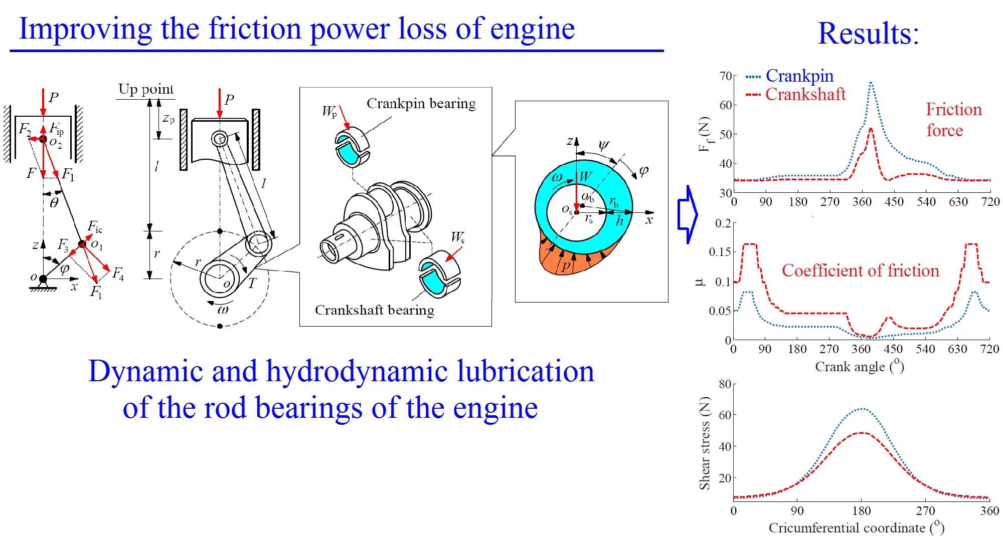
To determine the forces impacting on the CPB and CSB, a model of the SCM in Ref. [10] is applied. The SCM dynamic model is shown in Fig. 1(a), where ω, l, and r are the angular velocity, the radius of CSB, and the connecting rod length.
Fig. 1The dynamic mode of SCM and the lubrication model of journal bearings
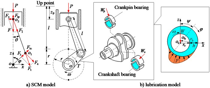
Based on the model in Fig. 1(a), the acceleration and inertial force of the piston and small-rod-end are calculated by:
where λ=r/l, m is the total mass of the piston and small-rod-end.
In the working process of the engine, the pressure of the combustion gas (P) impacting the piston peak also impacts the CPB and CSB. Based on the model in Fig. 1(a), the impacting forces on the CPB are calculated as follows:
where Fic is the centrifugal inertial force of the mass of big-rod-end of connecting rod mbr.
Therefore, the total impacting forces of Wp and Ws on the CPB and CSB are calculated by:
The Wp and Ws are then used as the internal dynamic loads to analyze the FPL of the CPB and CSB on improving the engine power.
To calculate the FPL of journal bearings of the engine, a lubrication model of journal bearings is given in Fig. 1(b). Herein, rs and rb are the radius of the shaft and bearing. e is the eccentricity between center of the shaft and bearing. ψ and φ are attitude angle and angular coordinate. W={Wp,Ws} is the internal load impacting on the CPB and CSB. h and p are the oil film thickness and pressure, and h is determined by h=rb-rs+ecosφ [10, 16].
Based on the hydrodynamic lubrication model of journal bearings given in Fig. 1(b), the general form of the Reynolds equation and its dimensionless form are written as follows [17, 18]:
where:
A=6ηωb2p0c2,β=brb,B=12ηb2t0p0c2,
and p0= 101325 (Pa) and b are the standard atmospheric pressure and bearing width.
Eqs. (3) and (5) are used to calculate the oil film pressure p, shear stress τ, and oil film thickness h of journal bearings.
2.2. The friction power loss of mixed hydrodynamic of journal bearings
The friction force of journal bearings: Under the impact of both the interfacial shears τis and asperity contacts τac on each journal bearing of CPB and CSB, the friction forces generated by the τis and τac [16, 17, 19] are determined as follows:
where and are the inter-fluid shear stress and shear stress of fluid; is the boundary shear stress; is the boundary friction coefficient; is solid contact pressure between shaft and bearing surfaces.
The friction coefficient of journal bearings: After and are calculated, their friction coefficients are calculated based on external loads impacting on the CPB and CSB as follows [18]:
Table 1The mathematical model's parameters
Parameters | Values | Parameters | Values |
/ mm | 129.5 | / mm | 25 |
/ mm | 40 | / µm | 4 |
/ kg | 0.264 | / ° | 0-720 |
/ kg | 0.45 | /Pas | 0.02 |
/ kg | 0.250 | / Nm-2 | 2×10⁶ |
/ mm | 20 | 0.309 |
To analyze the FPL between the CPB and CSB, the friction forces of and friction coefficients of } on improving the engine power are then chosen as objective functions.
3. Analysis of results
To compare the FPL between the CPB and CSB in the same operation condition of the engine, the parameters of the SCM and journal bearings listed in Table 1 and the experimental data of cylinder pressure at the low and high engine speeds of 2000 rpm and 6000 rpm in Ref. [16] given in Fig. 2 are applied to simulate the objective functions via the MATLAB software.
Fig. 2The combustion gas pressure [16]
![The combustion gas pressure [16]](https://static-01.extrica.com/articles/21666/21666-img2.jpg)
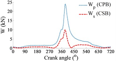
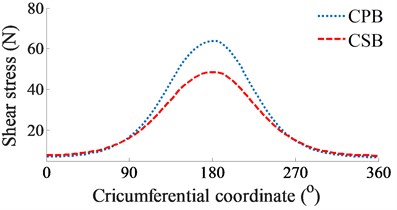
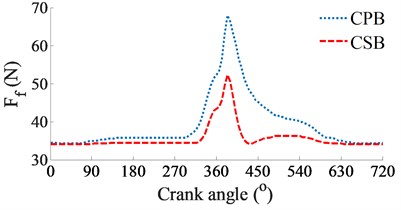
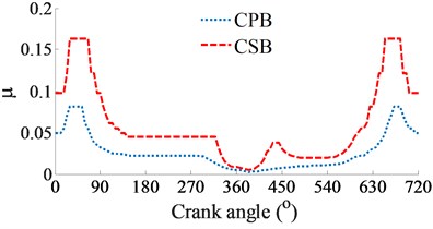
Fig. 3The simulation results of the CPB and CSB at a low engine speed of 2000 rpm
a) Impacting dynamic loads
b) Shear stress
c) Friction force of journal bearings
d) Friction coefficient of journal bearings
At a low engine speed of 2000 rpm and under the same of the cylinder pressure, Fig. 3(a) shows the simulation results of the and impacting on the CPB and CSB. It can see that is higher than , thus, the FPL of the CPB can be greatly influenced in comparison with the CSB. To clarify this issue, the shear stress, friction force, and friction coefficient are simulated and plotted in Figs. 3(b), (c), and (d), respectively. Under the impact of the internal loads, the shear stress of the CPB is higher than that of the CSB, as shown in Figs. 3(b). Therefore, the friction force generated in the gap of the CPB in Figs. 3(c) also increases in comparison with the CSB. This implies that the FPL on the CPB is higher than the CSB of the engine. Therefore, the design and optimization of the CPB structure had always been interested in previous studies [7, 10-11]. On the contrary, the friction coefficient of the CSB is higher than that of the CPB, as shown in Figs. 3(d).
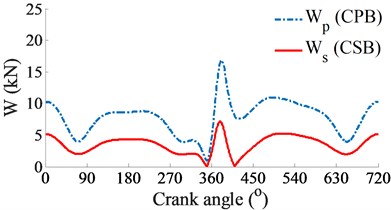
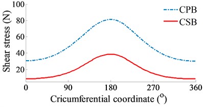
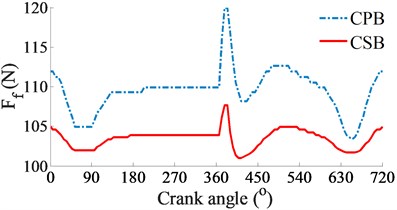
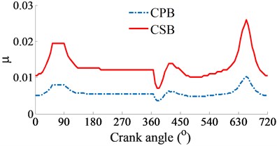
At a high engine speed of 6000 rpm and under the same of the cylinder pressure, Fig. 4(a) shows that the and impacting on the CPB and CSB from 0° to 360° and from 450° to the end are higher than the and , as shown in Fig. 3(a). This is due to the influence of the centrifugal inertial force of the mass of big-rod-end of connecting rod when increasing the engine speed. To compare the FPL between the CPB and CSB, the shear stress, friction force, and friction coefficient are also given in Figs. 4(b), (c), and (d), respectively. The simulation results also show that the FLP of the CPB and CSB at a high engine speed of 6000 rpm are similar at a low engine speed of 2000 rpm. It means that the FPL on the CPB is always higher than on the CSB under both the low and high engine speeds. However, the comparison result of the friction forces in Fig. 3(b) of 2000 rpm and Fig. 4(b) of 6000 rpm shows that the friction forces at 6000 rpm are strongly increased in comparison with the results at 2000 rpm. This is due to the impact of the shear stress of the oil film in the gap of journal bearings increased with the increase of the engine speed. Thus, the FLP of the engine at a high speed of 6000 rpm is higher than that at a low speed of 2000 rpm. This is also the reason that most engines should work at a low speed of 2000 rpm to reduce the friction power loss of the engine [8, 16].
Fig. 4The simulation results of the CPB and CSB at a high engine speed of 6000 rpm
a) Impacting dynamic loads
b) Shear stress
c) Friction force of journal bearings
d) Friction coefficient of journal bearings
4. Conclusions
Based on the SCM dynamic model, hydrodynamic lubrication model of the CPB and CSB under the impact of the internal dynamic load the and , the research results can be concluded via a numerical method and MATLAB software as follows:
1) Under both the low and high engine speeds of 2000 and 6000 rpm, the friction power loss of the crankpin bearing is higher than that of the crankshaft bearing. Thus, the lubrication problem for the crankpin bearing needs special attention.
2) Under the influence of the engine speeds, the friction power loss of the engine at the high engine speed is higher than that of at the low engine speed. Therefore, the engine speed should work and be stable at a low speed of 2000 rpm to optimize the lubrication efficiency and reduce the friction power loss of the engine.
3) The friction surfaces between the shaft and bearing surfaces should research and optimize via the design of the microtextures on the surfaces of the journal bearings to further improve the lubrication performance and reduce the friction power loss.
References
-
Arya K., Soheil R., et al. An intelligent cooling system and control model for improved engine thermal management. Applied Thermal Engineering, Vol. 128, 2018, p. 253-263.
-
Choi Y., Lee J., Jang J., Park S. Effects of fuel-injection systems on particle emission characteristics of gasoline vehicles. Atmospheric Environment, Vol. 217, 2019, p. 116941.
-
Tung S., Mcmillan M. Automotive tribology overview of current advances and challenges for the future. Tribology International, Vol. 37, 2004, p. 517-536.
-
He Z., Gong W., Xie W., et al. NVH and reliability analyses of the engine with different interaction models between the crankshaft and bearing. Applied Acoustics, Vol. 101, 2016, p. 185-200.
-
Lia Y., Chen G., Sun D., et al. Dynamic analysis and optimization design of a planar slider-crank mechanism with flexible components and two clearance joints. Mechanism and Machine Theory, Vol. 99, 2016, p. 37-57.
-
Meng X., Ning L., Xie Y., Wong V. Effects of the connecting-rod-related design parameters on the piston dynamics and the skirt-liner lubrication. Proceedings of the Institution of Mechanical Engineers, Part J, Journal of Engineering Tribology, Vol. 227, 2012, p. 885-898.
-
Wu Z., Nguyen V., et al. Design and optimization of textures on the surface of crankpin bearing to improve lubrication efficiency and friction power loss (LE-FPL) of engine. Proceedings of the Institution of Mechanical Engineers, Part J: Journal of Engineering Tribology, Vol. 2020, 2020, https://doi.org/10.1177/1350650120942009.
-
Mansouri S., Wong V. Effects of piston design parameters on piston secondary motion and skirt-liner friction. Proceedings of the Institution of Mechanical Engineers, Part J, Journal of Engineering Tribology, Vol. 219, 2005, p. 435-449.
-
Guzzomi A., Hesterman D., Stone B. Variable inertia effects of an engine including piston friction and a crank or gudgeon pin offset. Journal of Automobile Engineering, Vol. 222, 2008, p. 397-414.
-
Nguyen V., Wu Z., Le V. Optimization of crankpin bearing lubrication under dynamic loading considering effect of micro asperity contact. Industrial Lubrication and Tribology, Vol. 139, 2020, https://doi.org/10.1108/ILT-02-2020-0072.
-
Jiao R., Nguyen V., et al. Optimal design of micro-dimples on crankpin bearing surface for ameliorating engine’s lubrication and friction. Industrial Lubrication and Tribology, Vol. 72, 2020, https://doi.org/10.1108/ILT-04-2020-0152.
-
Gregory B., Katia L. Analysis of the dynamics of a slider-crank mechanism with hydrodynamic lubrication in the connecting rod-slider joint clearance. Mechanism and Machine Theory, Vol. 46, 2011, p. 1434-1452.
-
Zhang H., Hua M., Dong G., et al. Boundary slip surface design for high speed water lubricated. Tribology International, Vol. 79, 2014, p. 32-14.
-
Wang X., Zhang J., Dong H. Analysis of bearing lubrication under dynamic loading considering micropolar and cavitating effects. Tribology International, Vol. 44, 2011, p. 1071-1075.
-
Raj A., Sinha P. Transverse roughness in short journal bearings under dynamic loading. Tribology International, Vol. 16, 1983, p. 245-251.
-
Zhao B., Zhang Z., et al. Modeling and analysis of planar multibody system with mixed lubricated revolute joint. Tribology International, Vol. 98, 2016, p. 229-241.
-
Patir N., Cheng H. Application of average flow model to lubrication between rough sliding surfaces. Journal of Tribology, Vol. 101, 1979, p. 220-229.
-
Wu Z., Nguyen V., et al. Study on curved surface design of sliding pair based on stepped topography model. Industrial Lubrication and Tribology, Vol. 72, 2020, p. 86-92.
-
Patir N., Cheng H. An average flow model for determining effects of three-dimensional roughness on partial hydrodynamic lubrication. Journal of Tribology, Vol. 100, 1978, p. 12-17.
About this article
This research was supported by Open Fund Project of Hubei Key Laboratory of Intelligent Transportation Technology and Device, Hubei Polytechnic University, China (No. 2020XY105 and No. 2020XZ107), Talent Introduction Fund Project of Hubei Polytechnic University (No. 19XJK17R), and Research Project of Hubei Polytechnic University, China (No. 18XJZ05Q).
