Abstract
Ductility is an important aspect of the seismic performance of structures. Strong column and weak beam are important means to ensure the hinge plastic failure mechanism of frame structures. The corresponding provisions on failure mechanism of strong column-weak beam has been specified in design codes of various countries, but their differences are relatively large. This paper takes a plane frame as example which is designed according to the seismic code regulations of various countries, and then the difference in the failure mechanism of the designed frame under seismic actions is compared and analyzed. Finally, some suggestions are given to ensure the realization of strong column-weak beam mechanism.
Highlights
- The provisions of strong column-weak beam coefficient in different countries are systematically compared.
- The actual differences between countries in terms of strong column-weak beam are compared by an example.
- Some suggestions are given to ensure the realization of strong column-weak beam mechanism.
1. Introduction
The application of the frame structure is very extensive. To make the frame structure have good seismic performance, it is usually ensured that it has the necessary bearing capacity, sufficient deformability and good energy dissipation capacity. Strong column and weak beam are the global key measure affecting the seismic performance of the frame structures.
Fig. 1Comparison of energy-dissipating mechanisms: a) beam hinge mechanism, b) column hinge mechanism
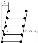
a)
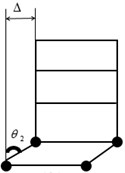
b)
The column hinge mechanism, shown in the Fig. 1(b), also referred to as a first-story mechanism [1], may impose plastic hinge rotations, which even with good detailing of the affected regions, would be difficult to accommodate. In codes of various countries, expressions to guide structures to achieve strong-column weak-beam failure mechanism are different, but their general directions are basically the same. It is expected that the rotation of plastic hinges occurring at column ends can be limited to a small amount under rare earthquake.
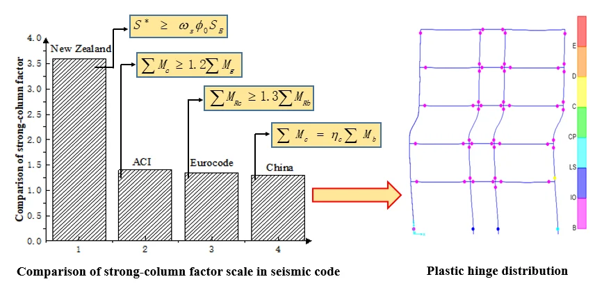
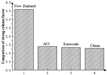
It can be seen that New Zealand code has the most detailed control measures for strong columns and weak beams to ensure that only selected plastic hinge mechanisms are produced.
The requirements of flexural bearing capacity ratio of column and beam in US, European and Chinese codes are similar, but the US, New Zealand, and Canadian codes all clearly require that the influence of cast-in-place floor slabs should be considered when considering the beam end flexural capacity [2].
Table 1Comparison of regulations
Code | Strong-column weak-beam expression | The meaning of physical quantity | Factor |
GB 50011-2010 | is the increase factor of the bending moment of the frame column end | is the increase factor of the bending moment at the end of the frame column | |
ACI318-05 | The ratio of the flexural bearing capacity of the column beam of the frame structure is at least 1.2 [3] | ||
Eurocode8 | Structural ductility is divided into high-level, intermediate-level and low-level | ||
New Zealand Standard | is the flexural overstrength factor [4] | ||
CSA23.3-04 | is the sum of the nominal bending capacity of the column |
Fig. 2Comparison of strong-column factor scale in seismic code
2. Influential factors of strong-column weak-beam need to be considered
Severe damage of the plastic hinge area occurred at the column ends is one of the prominent forms of earthquake damage in the reinforced concrete frame structures during the 2008 Wenchuan earthquake in China [5]. Why did the failure mode of the strong-column weak-beam advocated in codes fail to achieve? What factors affect the realization of strong-column weak-beam mechanism?
2.1. The actual bearing capacity of the beam end is overstrength
Here we must mention the overstrength concept, the over strength of the cross section should consider all factors that may cause the strength to exceed the nominal or ideal strength value. Here, the actual strength of the beam end refers to the true relative strength. The original strong column weak beam failure mode is intended to make the bending capacity of the column relatively “strong” and the bending capacity of beams is relatively “weak”.
Overstrength factors include steel strength is greater than the specified yield strength, additional strength enhancement of steel due to strain hardening at large deformations [1], unaccounted-for compression strength enhancement of the concrete due to its confinement, and strain rate effects. The cast-in-place beam and floor slab make the actual bending capacity of the beam end over strength, which affects the expected failure mode of the strong-beam weak-beam. Changes in design moments due to any redistribution of these, which the designer may have undertaken [4].
2.2. Dynamic magnification of column moments
To give columns a reasonably high degree of protection against premature yielding, allowance must be made for the fact that column moments during the inelastic dynamic response of a framed building to a severe earthquake will differ markedly from those predicted by analyses for static forces [4]. Before entering the yield, the bending stiffness of the members with different stress characteristics will change with different degrees as the stress increases. This change is especially noticeable after the structure enters yielding. To allow for such dynamic effects, the moments resulting from lateral static forces must be increased further if, as intended, column hinging above first floor is to be avoided. This is achieved by dynamic moment magnification factor .
3. Design example
An example of a plane frame is designed here (Fig. 3) and the detailed information is given below.
Table 2Material value of the structure
Member | Concrete strength grade | Longitudinal force | Stirrup |
Column-beam-floor | C40 | HRB400 | HRB400 |
Fig. 3Elevation view of the frame
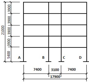
Table 3The design bending moment at column ends
Code | Strong-column weak-beam expression | Floor 3F | Floor 1F | ||||||
Axis A | Axis B | Axis A | Axis B | ||||||
GB 50011-2010 | 227.2 | 155.8 | 248.5 | 209.7 | 166.3 | 369.2 | 227.1 | 348.8 | |
ACI318-05 | 253.4 | 173.8 | 277.1 | 233.9 | 185.5 | 411.6 | 253.3 | 389.1 | |
Eurocode8 | 244.6 | 167.6 | 267.6 | 225.8 | 179.1 | 397.4 | 244.5 | 375.6 | |
New Zealand | 416.9 | 294.6 | 581.9 | 476.2 | 245.2 | 600.1 | 374.6 | 637.8 | |
The unit is kN*m. is for the top of the column, is for the bottom of the column. | |||||||||
Table 4The layout of rebar at column ends
Code | Floor 3F | Floor 1F | ||||||
Axis A | Axis B | Axis A | Axis B | |||||
T | C | T | C | T | C | T | C | |
4d18 | 4d18 | 4d18 | 4d18 | |||||
4d18 | 4d18 | 4d18 | 4d18 | |||||
4d18 | 4d18 | 4d18 | 4d18 | |||||
4d22 | 4d22 | 4d22 | 4d22 | |||||
is the tension side, is the compression side | ||||||||
The story drift rotation is less than 1/50 [6]. Reinforcement is the same according to Chinese, American and European specifications, so only plastic hinges in China and New Zealand are compared. The results of story drift rotation are shown in Table 5.
Table 5Story drift of structure under rare earthquake
Story | Axis No. of Columns | |||||||
A | B | C | D | |||||
G | N | G | N | G | N | G | N | |
1 | 1/167 | 1/164 | 1/166 | 1/163 | 1/167 | 1/162 | 1/166 | 1/167 |
2 | 1/166 | 1/158 | 1/167 | 1/158 | 1/168 | 1/161 | 1/166 | 1/165 |
3 | 1/162 | 1/160 | 1/168 | 1/156 | 1/168 | 1/160 | 1/167 | 1/162 |
4 | 1/178 | 1/161 | 1/180 | 1/160 | 1/181 | 1/162 | 1/178 | 1/164 |
5 | 1/202 | 1/203 | 1/200 | 1/204 | 1/201 | 1/203 | 1/203 | 1/204 |
“G” means Code GB 50011-2010, “N” means New Zealand Standard. | ||||||||
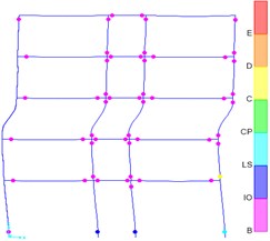
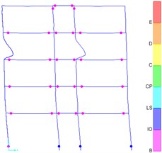
Fig. 4Plastic hinge distribution: a) design results according to Chinese code, b) the result of the design according to the New Zealand code
a)
b)
As shown in Fig. 4(b), most of the final plastic hinges of the structure designed according to New Zealand codes appear at the beam end. However, a relatively large number of structural plastic hinges designed in accordance with Chinese specifications appear at the column ends. The ratio of plastic hinges at the ends of structural columns calculated according to the New Zealand Code is 15 %, which is much smaller than the ratio of plastic hinges at the ends of structural columns calculated by the Chinese Code is 40 %. The New Zealand Code requires more detailed and strict regulation on the adjustment of strong-column weak-beam. It is easier to realize the failure mode of strong-column weak-beam under rare earthquakes. When designing according to New Zealand standards, plastic hinges appearing at the end of the column under rare earthquakes are later than those appearing at the end of the beam.
4. Conclusions
In this paper, the provisions of strong column-weak beam coefficient in different countries are systematically compared. Through an example, actual differences in national regulations are compared, and design suggestions are given.
1) The increase of strong-column coefficient cannot guarantee the realization of the real strong column and weak beam failure mechanism. Perhaps the method of increasing coefficients will eventually be replaced. The Chinese and US codes and European codes generally have similar results for the adjustment of strong-column weak-beam. The New Zealand code has the most stringent adjustment measures for strong columns and weak beams, and it is easier to form a reasonable failure mode.
2) For the frame structure, the lateral displacement curve of the structure is of shear type, the story drift of the lower floors is large. It is feasible to divide the structure into several parts along the height and adopt different measures of strong column-weak beam for different parts. With the exception of the column footings and in the top story, plastic hinges in columns should be avoided.
3) According to the interaction diagrams for reinforced concrete columns, the axial force of the column can be amplified when the column is under compression-control failures. When the column is under tensile-control failures, the bending moment and axial force are increased together. In this way, the failure mode of strong column and weak beam may be achieved.
4) Based on the combined internal force at the end of the member under small earthquakes, it is difficult to estimate the internal force at the column end under rare earthquakes. The effects of nonlinear amplification of internal forces under rare earthquakes should be considered.
References
-
Paulay T., Priestley M. J. N. Seismic Design of Reinforced Concrete and Masonry Buildings. John Wiley and Sons Inc., 1992.
-
Ye Lieping, Qu Zhe, Ma Qianli, Lin Xuchuan, Lu Xinzheng, Pan Peng Study on ensuring the strong column-weak beam mechanism for RC frames based on the damage analysis in the Wenchuan earthquake. Building Structure, Vol. 11, 2008, p. 52-59+67, (in Chinese).
-
Building Code Requirements for Structural Concrete (ACI318-02) and Commentary (ACI318R-02). American Concrete Institute, Committee 318, 2002.
-
Concrete Structures Standard. Concrete Design Committee, New Zealand Standard, 2006.
-
Li Yingmin, Luo Wenwen, Han Jun Control of failure mechanism for RC frame structure under strong earthquakes. Journal of Civil Engineering, Vol. 46, Issue 5, 2013, p. 85-92, (in Chinese).
-
GB 50011-2010 Code for seismic design of buildings. Beijing China Architecture and Buildings Press, 2010, (in Chinese).
-
Eurcode 8: Design of Structures for Earthquake Resistance. European Committee for Standardization, 2020.
-
Hu Yuxian Earthquake Engineering. 2nd Edition, Seismological Press, 2006, (in Chinese).
-
Wei Feng, Fu Jianping, Bai Shaoliang Actual control effect of strong-column and weak-beam measures of reinforced concrete frame structures in China. Building Structure, Vol. 8, 2007, p. 5-9.
-
Yang Hong, Bai Shaoliang The essence of the design method of bearing capacity difference of seismic reinforced concrete structure. Journal of Chongqing University of Architecture, 2000, p. 93-101, (in Chinese).
