Abstract
In order to relieve the dependence of load estimation upon the prior knowledge of mechanical system, an adaptive delayed inverse model is proposed for identifying the torque time history based on adaptive delay inverse system identification method. The LMS (least mean square) algorithm was used to identify the inverse model of the rotating system, which instead of system characteristic matrix inversion in common determination methods and ill-posed problem is avoided consequently. The adaptive delayed inverse model was used to identify the time-domain torque by analyzing the angular acceleration response data of the working state. The single-point time-domain torque of the bare shaft was identified by the angular acceleration response in the case of noiseless interference. The simulation results illustrate that the recognition results of this method is satisfied. It is proved by the experiment that the method is also feasible to the shaft system with disk coupling. The proposed method can be applied in practical engineering as it is not necessary to grip the mathematical model and system parameters in advance.
1. Introduction
In the engineering practice, the torque is often given to the rotating system such as the driving of the rotor system, the asymmetry of the shaft, the eccentricity of the disc and so on. The unnecessary torque will aggravate the vibration and even bring damage to the machine and equipment, which will reduce the service life [1-3]. Therefore, it is necessary to study the dynamic characteristics of the torque on the equipment. Currently, two methods are widely used in torque identification including frequency domain method and time domain method. In the frequency domain method, the input excitation and the output response of the system show a linear relationship. The inverse transformation of matrix is only needed in the load identification, which is easy to implement. However, the frequency method needs to perform Fourier Transform on the test signal, and the signal is required to have a certain length. Therefore, the frequency domain method is generally applicable to identifying steady dynamic loads or random loads, which is not suitable for the identification of impact loads. In addition, the frequency response function matrix of the system is generally morbid near the resonance frequency, causing a great error in load identification. The frequency domain method is based on the system linear assumption, which cannot identify the load of the nonlinear system. Compared with the frequency domain method, the time domain method does not need to perform Fourier Transform on the acquired signal, and the identification precision is not affected by the signal acquisition method [4-8]. In addition, the time domain method is capable of identifying transient shock loads. For nonlinear systems, the time domain method has more advantages.
At present, the widely used time domain methods mainly include deconvolution method, SWAT method [9], Kalman filter and recursive least squares method [10-13], inverse system method [14-16], etc. The deconvolution method needs to inversely calculate the time domainvibration characteristic matrix of the system, which is prone to ill-conditioned problems and affect the recognition accuracy of dynamic loads. The SWAT method is only applicable to structures with rigid body modes and the result is the resultant force of dynamic loads, so the application of SWAT method has great limitations. The Kalman filter and the recursive least squares method are based on the state space model of the system and can identify the time history of the unknown load. However, the method needs to grasp the statistical characteristics of the test noise and the process noise in advance, otherwise the recognition accuracy will be affected.
Combining the advantages and disadvantages of various identification methods, this paper intends to use the inverse system method to identify time domain loads. Inverse system method is a time domain identification method proposed by Wei [17]. In this method, the inverse model is used to transform the inverse problem of the load identification into the positive problem. However, the linear system only exists in the invertable, stable, controllable and observable conditions. Thus, the application of this method is limited. In view of the shortcomings of the inverse system, Steltzner used the truncated singular value decomposition (TSVD) method to get the inverse structural filter (ISF) of the system characteristic which was composed of Markov parameters [18]. The ISF was used to identify the load time history of the structure. But sometimes it is unstable. Based on the model of system state, an improved algorithm - Delayed Multistep ISF (DMISF) space is proposed by Allen to identify the time-domain load [16]. Nordström studied the load identification problem of the collocated system and non-collocated system based on the discrete state space model of the system, and used the time delay method to transform the identification of the ill-posed problem into a well-behaved one [19]. Because the inverse system method is not separated from the system state space model, it is necessary to know the prior knowledge of the system, so the application of the inverse system method is limited. In order to solve this problem, a time domain identification method based on adaptive delay inverse model is proposed by Zhou [20].
In view of these problems, this paper proposes a time domain method based on adaptive delay inverse model for load identification, which is used for dynamic load identification and identification of torque. This method uses an adaptive transversal filter to simulate the inverse characteristics of the system. It is independent of the state space model. Therefore, there is no need to master the mathematical model of the system. In this way, the workload of identification can be greatly reduced. In addition, the method uses an adaptive algorithm to identify the inverse model of delay, and does not need to inverse the system property matrix, thus avoiding the ill-conditioned problem in the matrix inversion process.
2. Theory of torque identification
The inverse modeling is implemented as a set of adaptive filters. The output signal of the rotor system is taken as the input signal of the adaptive filter, and the error signal is defined as the difference between the input signal of the rotor system and the output signal of the adaptive filter. The LMS algorithm adjusts the coefficients of the filter by using the negative gradient of the single sample variance of the error signal, instead of the negative gradient of the mean square error to minimize the quadratic performance index (mean square error or mean power of the error signal). Then the output of the adaptive filter will match the input of the rotor system best. It means that the torque on the rotor system is identified.
As shown in Fig. 1, a finite-length adaptive filter (finite impulse response filter) is chosen in this paper. As shown in Fig. 2, the delay inverse model of SISO (single input single output) system is simulated. Multi-frequency signal (such as white noise signal or sweep signal) is chosen as the input of the real rotation system . The output signal of the system is taken as the input signal of the adaptive filter. And the output of the adaptive filter is . The difference between the delay excitation and the output signal of the adaptive filter is taken as the error signal . The normalized LMS algorithm is used to adaptively adjust the weight coefficients of the filter until the mean square of the output error signal converges to a minimum. In this case, the adaptive filter weight vector is the best estimate of the time domain of SISO system inverse model. The adaptive inverse model of SISO system is obtained.
Fig. 1Schematic diagram of SISO system delay inverse model establishment
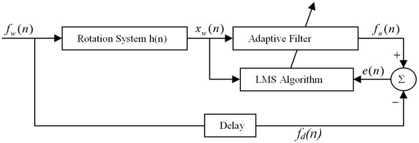
Fig. 2Finite impulse response filter

The output signal of the adaptive filter can be expressed as:
where the output vector of the system is . The adaptive filter weight vector is and is the filter order. The excitation of white noise excitation after -step delay is:
Then the error signal is:
And the square of the error signal is:
where the mean square of the output error signal is:
According to the normalized LMS algorithm the adaptive filter weight vector is continuously adjusted until the mean square of the error is minimized:
where is the convergence factor, is the leakage factor. Specific process of the identification is shown as Fig. 3.
Fig. 3Flowchart for time domain identification
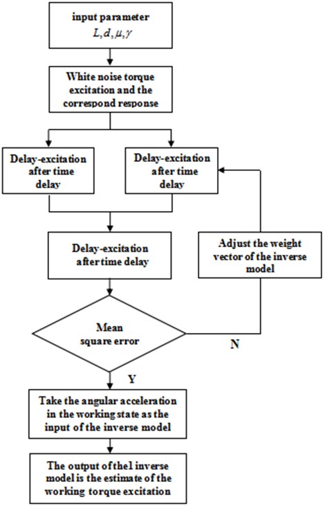
Theoretical analysis shows that when there is no noise, the minimum mean square error will be zero. At this time, the adaptive filter weight vector can accurately reflect the time-domain inverse characteristic of the system. The calculation of the third part is done by applying the operation sequence of Fig. 3.
3. Simulation analysis of the torque identification
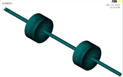
By using ANSYS to establish the disk-shaft system finite element model shown as Fig. 4, the parameters of the system are shown in Table 1.
The boundary conditions at both ends are both free boundary conditions. Two different time-varying torque excitation are applied to the left end of the shaft respectively. Make the excitation frequency of the second is included in the first one. Using the transient analysis module of ANSYS to get the angular acceleration response of the right end of the shaft. Export the data and write a program to establish an inverse model LMS adaptive.
Table 1Geometric and material parameters of the system
Geometric parameters | Material parameters | ||
Length (Lateral axis) / m | 0.3 | Density / (kg/m3) | 7800 |
Radius (shaft) / m | 0.0125 | Poisson ratio | 0.3 |
Radius(disk) / m | 0.125 | Elastic modulus / Pa | 2.1×10¹¹ |
Length(disk) / m | 0.1 | Grid type | BEAM188 |
Length (the shaft between disks) / m | 0.4 | Mesh length / m | 0.002 |
Fig. 4The bare shaft finite element model
Firstly, a torque excitation containing multi-frequency is applied to the left end of the shaft in the form:
Time step is set to 0.05 s. Get the angular acceleration response of the right end of the shaft as shown in Fig. 5.
The response signal under the torque load is used as the input signal of the inverse model. The difference between the output signal of the inverse model and is defined as the error signal. The adaptive filter automatically adjusts its own weight vector to achieve the optimal filtering, as shown in Fig. 1.
Single-frequency, dual-frequency and four-frequency torsional excitation are applied to the left end of the shaft respectively. The above three excitation are identified by using the optimal weight vector. Filter order 5, delay time step 3, convergence factor 0.1, leakage factor 1.
Single frequency:
Dual- frequency:
Four frequency:
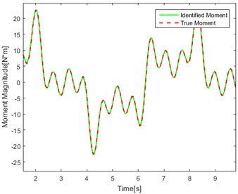
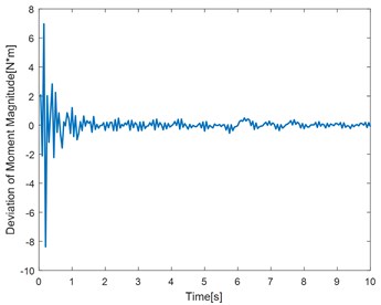
The angular acceleration responses of the right end point under various forms of excitation are obtained respectively. Using the inverse model LMS adaptive method to identify the torque excitation and the identification results is shown as Fig. 6.
Fig. 5The angular acceleration response of the right end of the shaft
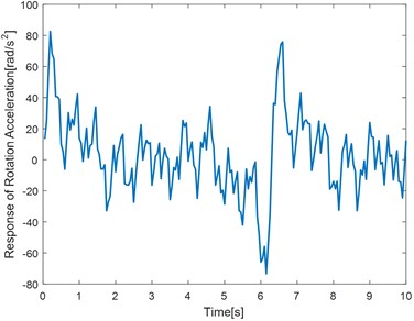
Fig. 6The identification results of the bare shaft
a) Single frequency effect of identification
b) Single frequency convergence diagram of deviation
c) Dual frequency effect of identification
d) Dual frequency convergence diagram of deviation
e) Four frequency effect of identification
f) Four frequency convergence diagram of deviation
Table 2Error analysis table
Torque type | Time (s) | True torque () (N·m) | Identification torque () (N·m) | Percentage of error (%) ·100 % |
Single frequency | 3.45 | 0.230 | 0.241 | 4.875 % |
5.35 | –0.371 | –0.354 | 4.531 % | |
7.80 | 2.056 | 2.092 | 1.757 % | |
9.05 | 2.279 | 2.318 | 1.723 % | |
Dual frequency | 2.10 | –3.466 | –3.623 | 4.500 % |
3.50 | –3.315 | –3.141 | 5.247 % | |
5.05 | 4.354 | 4.450 | 3.351 % | |
7.85 | –5.127 | –5.169 | 0.816 % | |
Four frequency | 1.95 | 20.960 | 19.770 | 5.684 % |
4.65 | –5.823 | –5.649 | 2.981 % | |
7.70 | 9.993 | 9.876 | 1.188 % | |
9.30 | –4.069 | –4.147 | 1.923 % |
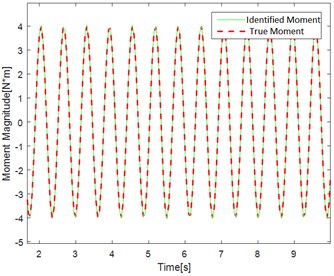
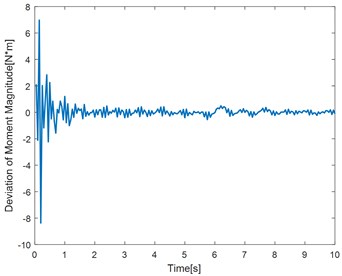
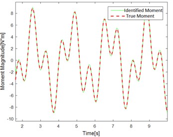
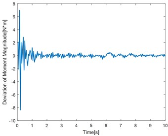
Fig. 6(a, c, e) show the identification of the torque curve and the true torque curve. The solid green line is the identified torque and the red dotted line is the true torque. Fig. 6 (b, d, f) represent the error curve between the identification torque and the true torque. It can be seen from the error curve that the error converges over time.
Table 2 randomly intercepts the data in the curve for error percentage comparison. It can be seen that the error is within the allowable range. The method has better identification effect and higher precision.
4. Experimental verification of the torque identification
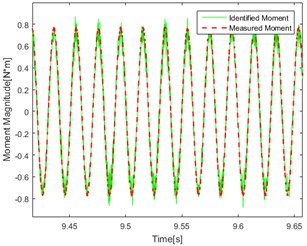
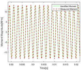
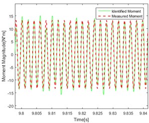
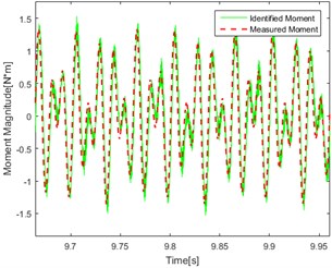
Experiments of torque identification on a rotating shaft system with disc are carried out to verify the feasibility and effectiveness of the LMS adaptive delay inverse system method. The shaft system with disc is shown as Fig. 7. The end of the shaft is connected with a horizontal steel bar by rigid, which can rotate freely with the shaft. The exciter is suspended by a soft spring and it is connected with the edge of the steel bar by the vibration bar. A force sensor is used to measure the force transmitted to the bar. The acceleration sensors are arranged on the discs to measure the tangential acceleration of the discs.
Fig. 7The rotating shaft system test bench
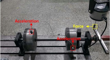
Firstly, a series of random excitation are applied to the end of the steel bar. The force signals and the tangential acceleration responses of the discs are acquired by the force sensor and the acceleration sensors. The equivalent torque and angular acceleration are calculated by the following relational expression:
where is the distance between the end of the steel bar and the axis of the shaft, is the radius of the disc, a is the tangential acceleration of disc. is the applied torque and is the angular acceleration of the disc.
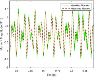
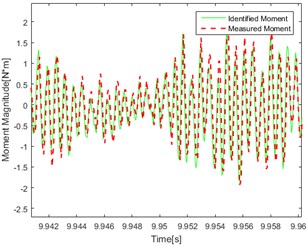
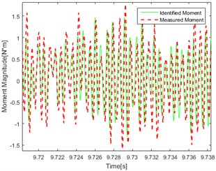
Fig. 8The identification results of the rotating shaft system
a) Single-frequency (50 Hz) Point 1
b) Single-frequency (50 Hz) Point 2
c) Single-frequency (500 Hz) Point 1
d) Single-frequency (500 Hz) Point 2
e) Dual-frequency (50 and 80 Hz) Point 1
f) Dual-frequency (50 and 80 Hz) Point 2
g) Pseudo-random Point 1
h) Pseudo-random Point 2
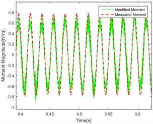
The data are brought into the inverse model program to identify a set of optimal weights, then the single-frequency, dual-frequency and pseudo-random excitation are respectively applied to the end of the steel bar. Repeat the above step to obtain the magnitude of the equivalent torque and angular acceleration response. Using the optimal weight to identify the magnitude of the torque under different excitation and the identification results are shown in Fig. 8.
Compare the figures above, the conclusions can be got as follows: In the figures, the red line represents the real test results. The green line represents the calculation result using the delay inverse model method. By comparing the data in each graph, it can be found that the red line and the green line are in good agreement with each other, and the accuracy and applicability of the method are verified. At the same time, it can be found in the comparison of the effect of identification under different kinds of excitation that the effect of identification under single frequency excitation is relatively better than under the random one.
As shown in Fig. 8(a, b, e, f) There are jagged deviations in the identification (mainly concentrated at the peak) which is due to the introduction of low frequency. Compared with the effect of identification under the same excitation, it can be found that the degree of agreement of the calculated value and the measured value in point 1 and point 2 are approximately similar which proved that the effect of identification is not related to the point selection of the response for torque source identification.
5. Conclusions
In this paper, an adaptive delay inverse model is used to identify the time-domain torque acting on the structure. The effectiveness of the method is verified by simulation and experiment. The method is suitable for identifying the steady-state excitation and the transient excitation. In the absence of prior knowledge of the system, this method has great advantages.
In this paper, the torque is recognized under conditions of SISO (single input single output) and noiseless interference. But the existence of multiple torque is more common in engineering practice. Therefore, future research can be carried out for MIMO (multiple input multiple output). And it can be considered to apply some noise part to the torque excitation to verify the feasibility of LMS adaptive delay inverse model in more general cases.
References
-
Jacquelin E., Bennani A., Hamelin P. Force reconstruction: analysis and regularization of a deconvolution problem. Journal of Sound and Vibration, Vol. 265, Issue 1, 2003, p. 81-107.
-
Law S. S., Bu J. Q., Zhu X. Q., et al. Vehicle axle loads identification using finite element method. Engineering Structures, Vol. 26, Issue 8, 2004, p. 1143-1153.
-
Yanyutin E. G., Yanchevsky I. V. Identification of an impulse load acting on an axisymmetrical hemispherical shell. International Journal of Solids and Structures, Vol. 41, Issue 13, 2004, p. 3643-3652.
-
Yu Y., Zhao H., Chen B. Set-membership improved normalized subband adaptive filter algorithms for acoustic echo cancellation. IET Signal Processing, Vol. 12, Issue 1, 2015, p. 42-50.
-
Collett T. S., Boswell R., Lee M. W., et al. Evaluation of long-term gas-hydrate-production testing locations on the alaska north slope. Structural Control and Health Monitoring, Vol. 21, Issue 6, 2014, p. 868-889.
-
Law S. S., Bu J. Q., Zhu X. Q. Time-varying wind load identification from structural responses. Engineering Structures, Vol. 27, Issue 10, 2005, p. 1586-1598.
-
Zhou Q., Liu Y., Wang X., et al. Structural damage detection technique with limited input and output measurement signals. Journal of Vibration Measurement and Diagnosis, Vol. 28, Issue 5, 2012, p. 229-243.
-
Wei T., Guo G., Wei T., et al. Performance comparison between matched filter and locally optimal detector for composite hypothesis test with inaccurate noise. IET Signal Processing, Vol. 12, Issue 2, 2018, p. 163-168.
-
Chen L., Zhou H. A method of the sum of weighted acceleration in dynamic loads identification. Noise and Vibration Control, Vol. 3, Issue 1, 2002, p. 14-16.
-
Hwang J. S., Kareem A., Kim W. J. Estimation of modal loads using structural response. Journal of Sound and Vibration, Vol. 326, Issues 3-5, 2009, p. 522-539.
-
Lin D. C. Input estimation for nonlinear systems. Inverse Problems in Science and Engineering, Vol. 18, Issue 1, 2010, p. 673-689.
-
Lourens E., Papadimitriou C., Gillijns S., et al. Joint input-response estimation for structural systems based on reduced-order models and vibration data from a limited number of sensors. Mechanical Systems and Signal Processing, Vol. 29, Issue 1, 2012, p. 310-327.
-
Naets F., Cuadrado J., Desmet W. Stable force identification in structural dynamics using Kalman filtering and dummy-measurements. Mechanical Systems and Signal Processing, Vol. 50, Issue 1, 2015, p. 235-248.
-
Uhl T. The inverse identification problem and its technical application. Archive of Applied Mechanics, Vol. 77, Issue 1, 2007, p. 325-337.
-
Czop P., Mendrok K., Uhl T. Application of inverse linear parametric models in the identification of rail track irregularities. Archive of Applied Mechanics, Vol. 81, Issue 1, 2011, p. 1541-1554.
-
Allen M. S., Carne T. G. Delayed, multi-step inverse structural filter for robust force identification, Mechanical Systems and Signal Processing, Vol. 81, 1, p. 1036-1054.
-
Wei X., Song B., Zheng X. A method of inverse system to identify force. Journal of Vibration, Measurement and Diagnosis, Vol. 15, Issue 1, 1995, p. 37-43.
-
Steltzner A. D. Input force estimation, inverse structural system and the inverse structural filter. The University of Wisconsin-Madison, Vol. 14, Issue 1, 1999, p. 33-44.
-
Nordström L. J. L., Nordberg T. P. A time delay method to solve non-collocated input estimation problems. Mechanical Systems and Signal Processing, Vol. 22, Issue 1, 2004, p. 1469-1483.
-
Zhou P., Li W., Shuai Z. Adaptive delayed inverse system method for reconstruction of multiple input excitations. Journal of Vibration and Shock, Vol. 33, Issue 1, 2014, p. 41-45.
About this article
The research work is supported by Marine Low-Speed Engine Project-Phase I.
