Abstract
In most of rotating kind of machinery, misalignment is commonly observed defect. Though machines are installed to zero-zero aligned condition in initial stage, in due course of run time operation misalignment get introduced due thermal distortion, asymmetry of forces exerted and inadequate assembly of parts. This paper presents a method of misalignment prediction from output vibration signal which is based on combined DWT (Discrete Wavelet Transform) and Fuzzy Logic approach. DWT helps in multilevel decomposition of vibration signal to understand where and at what instant misalignment occurs. This involves selection of mother wavelet. The FIS (Fuzzy Inference System) is combined with DWT to predict degree of misalignment present. An inclusion of FIS has improved prediction accuracy of Degree of Misalignment (DoM) which has claimed error less than one percent (1 %).
1. Introduction
Industries are more concern about efficiency and performance of machines which are used for different process. Majority of cases prime movers used in industry are electrical motors coupled with output system. Commonly occurred problem in mechanical based industry which has extensive use of rotating machinery is misalignment. Approximately, 40 % of annual maintenance cost is spend to tackle problem of misalignment in case of rotating machinery [1, 2]. At the time of installation and recondition it is aligned to zero-zero state in static condition. But slowly misalignment occurs in the system in due course of working period [2]. Misalignment is entirely disagree stage between center line of input and output coupled shaft. Generally, they are of two type viz. parallel misalignment and angular misalignment. To ensure minimum downtime, it is essential to apply continuous monitoring of aligned condition of all rotating machinery. Especially in power generation and aviation sector, machinery involved are costlier, it becomes vital priority to keep coupled system in close limit of permissible alignment during run time. This helps to avoid any kind of catastrophic failure. Several attempts are made to contribute shaft misalignment and its condition monitoring through various techniques. Commonly, condition monitoring involves comparing vibration signals obtained through faulty and healthy conditions. Mainly in condition monitoring fault diagnosis is primarily considered which involves data collection, data processing, fault identification and fault classification [3-9]. Alokkumar, et al. [10] attempted to diagnose shaft misalignment using motor current signature analysis (MCSA) by conducting number of tests using spectra quest machine fault simulator. Author tried to analyze shaft displacement with stator current under real time fully loading condition. In [11], the frequency analysis using Fast Fourier Transform (FFT) of vibration signals generated from blade-to-stator rubbing of rotating machinery did not show effect on vibration signal. Hence, to identify this additional cause of vibration in system, non-stationary signals have been analyzed using Continuous wavelet Transform (CWT) and Wavelet Packet Transform (WPT). It is concluded that the unverified and undiscovered WPT analysis provides better results than FFT and CWT. In related work done for misalignment and its classification, focus is not given to predict degree of misalignment.
The temperature monitoring technique for misalignment detection of wind turbine is proposed in [12]. An infrared thermometer is used for online condition monitoring which is specially referred to misalignment. Non-contactable method of condition monitoring has been derived using this approach for critical points like coupling midpoint etc. Temperature rise has contribution of many other causes, hence rise in temperature will not be indication of only misalignment and correct measurement of it is uncovered. A test rig to analyze misalignment condition of rotating shaft in running condition using laser beam arrangement have been proposed for measurement of shaft misalignment between 0.5 mm to 2.5 mm [13]. This technique requires some modification to measure misalignment on precise scale of 0.02 mm to 0.3 mm. Arebi et al. [14] has compared analysis of vibration signal using Micro Electro Mechanical Systems (MEMSs) based wireless sensor with contact type accelerometer (conventional vibrometer). The amplitude of spectra observed in vertical direction by wireless sensors are more distinguishable at various degree of misalignment at 2X than 1X running speed of shaft. Also, same results are confirmed using Finite Element Method (FEM) analysis for high order model of coupled rotor system considering bending moment and deflection [15]. Effects of angular misalignment on motor torque, instantaneous power and current are studied through dynamic simulation [16]. The presence of backward or negative whirling is sure indication of rotor misaligned condition. The inner loop orbits are an indication of parallel misalignment and outer loop orbits are an indication of angular misalignment. The result due to misalignments are also seen with side bands in the stator current at frequency f and ±2f which is an indication of presence of angular misalignment [17]. The change in harmonics present in vibration signal due to angular and parallel misalignment is analyzed in [18] using one sided FFT, two sided spectrum and orbit plots. Vibration response of coupled rotor is studied under steady state for sub-critical speeds for both parallel and angular misalignment. Lateral vibrations are seen with higher harmonics for both type of misalignment.
P. N. Saavedra et al. [19] made an attempt for theoretical analysis and experimental validation of shaft misalignment. It is observed that vibration characteristics such as frequency spectrum and phase shift are different for various degree of misalignment and type of coupling. it is observed that vibration response due to misalignment has influence of shaft stiffness and type of coupling used which is measure and not considered in vibration analysis. Any kind of misalignment present in shaft leads to an additional torsional vibration which is measured by DK-II torsional vibration measuring systems and verified experimentally [20]. Torsional vibrations responses for parallel misaligned shaft are observed with 1X and 2X running speed of shaft [21]. Umbrajkaar Amit, A. Krishnamoorthy have given an overview of mathematical modelling and related set up for analysis of shaft misalignment [22]. Simon J. Watson has presented a bearing fault analysis of wind turbine using DWT analysis [23]. S. Mahdi Mousavi et.al have considered motor Current Signature Analysis (MCSA) in combination with DWT to predict faults in induction machine under variable load and speed condition [24]. A combined approach of DWT-ANN and DWT-Fuzzy has been considered in fault analysis of rolling element bearing for rotating machinery [25]. An effective guidelines are given for online monitoring of bearing faults using Daubechies (DB)mother wavelet (DB-8) as suitable for this analysis. A combined approach of DWT and Fuzzy has been used to monitor tool wear and tool breakage under various conditions [26]. The combination of DWT-Fuzzy system under cutting parameters such as speed and feed rate are verified with current features and observed that this combination is effective for analysis of current which false under Motor Current Signature Analysis (MCSA). The unique feature of shaft orbit is used as a main parameter for fault diagnosis of large rotating machinery to extract feature using novel method of statistical Fuzzy vector chain code [27]. Which has benefits like invariance, easy calculation and high separability.
The DWT has been effectively used in various domain such as distinct signal coding, combustion failure analysis of I.C. engine, in detection of abrupt discontinuties, in compression of large amount of data etc. There is lack of literature review about application and development of discrete wavelet transform and fuzzy logic in prediction of shaft misalignment. It can be summarized from above review, that most of work related to misalignment is implemented with FFT. In analysis of non-stationary signal, multi-level decomposition is not possible with FFT and time domain information may be lost. Hence, to extract all feature of information in both time and frequency domain, wavelet tools are applied with suitable choice of mother wavelet function. Use of Discrete Wavelet Transform (DWT) is proposed in this work. To improve accuracy in result prediction a combined approach of DWT and Fuzzy Logic is implemented in this work.
2. Methodology
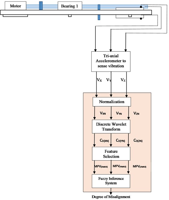
The tri-axial accelerometer is mounted on Bearing-2 to sense vibrations (Vd) in axial, vertical and lateral direction i.e. VX, VY and VZ respectively. The vibration signals are converted into data packets i.e. VXn, VYn and VZn, each packet consists of 60 samples for further analysis i.e. n= 1,…, 60. The amplitude of vibration signals is varying with respect to misalignment of coupled rotor and shaft, and different operating conditions of motor like variable load and speed. The frequent variations in amplitude of vibrations do not support to identify misalignment actually. To avoid misinterpretation under different operating conditions of motor, vibration signal is normalized. The vibration signals are normalized by using Eq. (1), Eq. (2) and Eq. (3):
where VXn, VYn ,VZn are vibration signal data packets in x, y, z direction respectively. VXNn, VYNn. VZNn are normalized vibration signals in x, y, z direction respectively.
The FFT converts time domain signal into frequency domain by losing information in time domain. Hence, further level of analysis is not possible using FFT. DWT makes an effective multilevel analysis to retrieve correct information which lies in non-stationary signals. The DWT calculates detailed coefficient (CD) and approximate coefficient (CA) of signal using low pass filter (LPF) and high pass filter (HPF) respectively. The impulse responses of LPF and HPF are given by Eq. (4) and Eq. (5):
where h and g are filter coefficient, n is number of sample, k is shifting parameter.
DWT is used for feature extraction, from these extracted feature different features can be selected like Maximum (max), Minimum (min), Median (med), Mean (mean) and Standard deviation (std). The max and min features are enough to predict degree of misalignment with the help of Fuzzy Inference System (FIS). These features are called as Misalignment Prediction Variables (MPVs) and calculated by using Eq. (6) and Eq. (7):
The Fuzzy based DWT operational module is as shown in Fig. 3,is implemented using three inputs MPVdmax viz. MPVXmax, MPVYmax and MPVZmax and one output variable which predicts degree of misalignment.
3. Experimentation
An experimental set up as shown in Fig. 2 is prepared to study shaft vibrations due to misalignment. The main objective of set up design is to examine aligned and misaligned condition in both static and dynamic states. It is necessary to ensure aligned condition of shaft in both condition for efficient performance of machinery. Aligned state of system in static condition i.e. before and after assembly of coupled system is examined by face and rim dial indicator method as shown in Fig. 1. A fixture is developed exclusively for this method to set dial indicator at right position. The face attached dial will give conformation of angular deviation and rim attached dial explains about offset deviation.
Fig. 1Face and rim method attachment with fixture
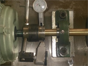
Fig. 2Experimental setup
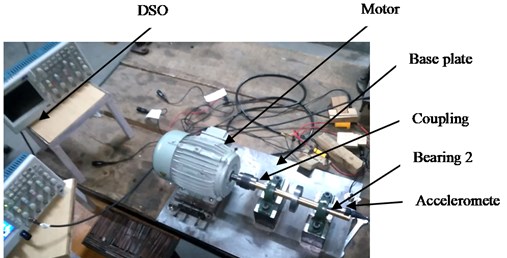
The set up includes key components viz. motor, motor block, coupling, rotor, bearing, variable frequency drive (VFD) and data acquisition system (DAS) for data collection. A 3-phase A.C. induction motor with 1.2 Amp is used. VFD is used to set different required speed of motor accurately. The speed range finalized for this experimentation case is in the range of 0-2100 rpm. The output shaft of diameter 3/4 inch is supported between two bearings with rotating disc. To ensure elimination of unbalance completely, the entire shaft with rotor is tested and balanced on dynamic balancing machine. For damping out any of vibration source, entire base plate set up is supported on vibration isolator pad of 0.3 ton capacity. An accelerometer (Model 352B70, 10 mV/g, (1 to 10000 Hz) 0.0005 g rms) is attached at three positions alternately at second bearing location to record vibration signals in X, Y, Z directions i.e. along axial, vertical and transverse directions respectively. The accelerometer output given to DSO which is equipped with four channels for input data. The vibration signals are further processed to retrieve information of misalignment. Initially, test rig is set to zero-zero aligned condition in static phase with the help of face and rim method. In run time, an artificial misalignment was introduced with interval of 0.02 mm (0.78740 mils) for different standard motor rating rpm viz. 500, 740, 1000, 1440 and 1800. The entire set of reading followed for parallel and angular misalignment.
Fig. 3Proposed DWT and fuzzy based misalignment prediction
4. Implementation
Vibration signals caused due to misalignment are recorded as output referred in three direction viz. longitudinal (X), Vertical (Y) and transverse (Z). A sample output signal of parallel misalignment in vertical direction is compared and analyzed for constant speed of 1800 rpm and misalignment in the range of 0 to 0.2 mm as shown in Fig. 4. It is observed that Overall Vibration Level (OVL) is increasing with incremental change in degree of misalignment. This observation is validated with all three direction of vibration response for any value of misalignment degree in mentioned range. It is observed that in vibration signal due to misalignment, OVL is seen at 1X, 2X operating frequency of machinery [21]. Accordingly, it is seen with experimental reading for considered sample of signal, OVL is expected at 30 Hz which is in confirmation with 1X operating frequency.
Majority of times in analysis of non-stationary signals to retrieve information in time domain is not possible. In such cases of signal analysis different techniques are considered to be used to get information in required domain.
DWT is one of the effective techniques considered in similar condition which is exercised in both time and frequency domains. DWT is very effective in cases of non-stationary signal analysis. DWT makes an effective multi-level analysis to elicit information with non-stationary signals. The DWT calculates Detailed Coefficient (DC) and Approximate Coefficient (AC) of signal. The DC values of vibration signal for varying degree of misalignment is depicted in Fig. 5. The sample signal for constant speed of 1800 rpm with misalignment range between 0 to 0.2 mm is referred. In this analysis, signal with zero misalignment is treated as healthy condition signal for further comparison. It is observed that many times clear fault differentiation is not possible, as common faults are associated with common frequency, as observed with in Table 1. In such cases, DWT analysis helps to predict fault occurrence and find distinguished feature associated with fault information.
Fig. 4Vibration signals in vertical direction for parallel misalignment at 1800 rpm
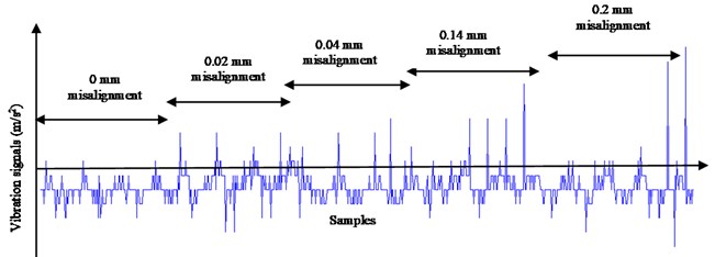
Fig. 5Detailed coefficients of vibration signals at second level of decomposition
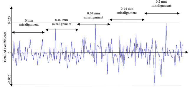
Table 1Mechanical fault and corresponding frequency (courtesy ISO 10816 mechanical vibration)
Sr. No | Mechanical fault | Related frequency |
1 | Primary cause: oil whirl Secondary cause: bad drive belt, sub-harmonic resonance, background vibration | 1/2 X RPM |
2 | Primary cause: unbalance Secondary cause: eccentricity in gears and pulley, bent shaft, electrical interference, misalignment | 1X RPM |
3 | Primary cause: misalignment (high axial vibration) secondary cause: mechanical looseness, unbalanced reciprocating forces, bad belts, mechanical looseness | 2X RPM |
4 | Primary cause: crack, combination of misalignment secondary cause: mechanical looseness or excessive clearance | 3X RPM |
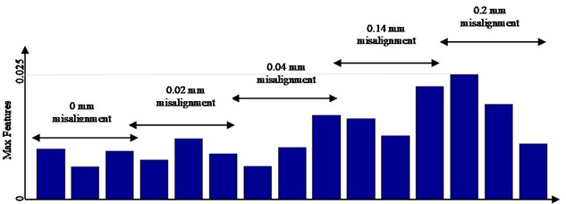
Different mother wavelets are available in DWT like DB, HAAR, BIOR, COIF, DMEY, RBIO, SYM etc. Selection of mother wavelet plays vital role as different mother wavelet shows unlike results of analysis for the same signal. This is based on characteristics of mother wavelet like vanishing moments, symmetry etc. [9]. It is revealed that DB-2 mother wavelet is suitable in analysis of vibration signal predicting misalignment conditions [22]. DCs and ACs are obtained using DWT using Eq. (4) and Eq. (5). It is observed that value of DC is also increasing with incremental change in degree of misalignment as shown in Fig. 5. Max features of DC as shown in Fig. 6 are compared for sample signal recorded at 1800rpm with varying misalignment from 0 to 0.2 mm.
Fig. 6Max value of detailed coefficients
5. Fuzzy logic architecture
5.1. FIS design
The Max features i.e. MPVs obtained from DWT are given as input to Fuzzy Inference System (FIS) to predict degree of misalignment as shown in Fig. 7. Three inputs like MPVd are given to FIS i.e. MPVdX, MPVdY and MPVdZ. The output of FIS is Degree of Misalignment (DoM).
Fig. 7Structure of fuzzy inference system

5.2. Membership function selection
Fuzzification involves a process of transforming crisp inputs into fuzzy linguistic inputs. In this work, crisp inputs are MPVs in three directions such as MPVxMax, MPVYMax and MPVzMax which are values of Max features. In fuzzification, input membership functions are quantified as LOW, LOW MED, MED, MED HIGH, HIGH AND VERY HIGH as shown in Fig. 8. Usually three type of fuzzy sets are considered viz. Normal, Sub-normal and Convex fuzzy set. In this case, as degree of misalignment varies with change in speed and vice versa, hence convex fuzzy set is used.
5.3. Formation of rule base
In fuzzy logic, normally three forms for rule base formation are referred viz. conditional statement, unconditional statement and assignment statement. Assignment statements are considered for formation of rule base. The assignment statement illustrated in formation of rule base is as explained below:
IF (MPVX= LOW && MPVY= LOW && MPVZ= LOW),
THEN (DoM= LOW),
IF (MPVX= MED && MPVY= MED HIGH && MPVZ= MED HIGH),
THEN (DoM= MED HIGH),
IF (MPVX= HIGH && MPVY= MED HIGH && MPVZ= VERY HIGH),
THEN (DoM= VERY HIGH).
5.4. Defuzzification
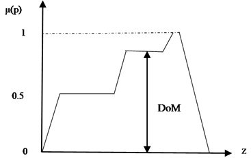
Defuzzification is the process of producing quantifiable results in fuzzy logic for given fuzzy sets and corresponding membership function. The output membership functions are as shown in Fig. 9. This is achieved by transforming fuzzy sets into crisp values which is precise value of degree of misalignment. In this process centroid of area defuzzification is considered as shown in Fig. 10 for crisp output values:
where, μ(p) is Membership function, zdz is weighted output variable.
Fig. 8Input membership functions
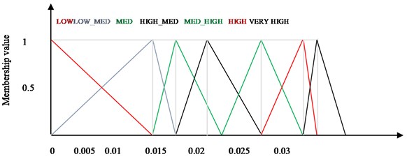
Fig. 9Output membership functions
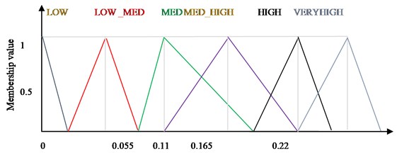
Fig. 10Defuzzification by center of area method
6. Result and discussion
In this work, DB 2 mother wavelet is used for feature extraction. An attempt is made to apply DWT and FL in combined mode of operation. After careful observation of feature of DC, an assignment statement fuzzy set is used in rule base formation. Also, in fuzzification triangular membership functions are applied for input and output variables. In defuzzification process, an approach of center of area method is used to get output from FIS in specific required form such as DoM. It is clear that values of DC changes with change in speed or misalignment degree. The Max DC feature have also changed with change in variable condition as shown in Table 2. The Max value of DC feature is also one of reference to identify change in input variables.
Table 2Degree of misalignment and their max features
Degree of misalignment | Value of max features | Selected max feature for FIS input |
0.0 mm | 0.0096 | 0.0096 |
0.0062 | ||
0.0092 | ||
0.02 mm | 0.0075 | 0.0116 |
0.0116 | ||
0.0087 | ||
0.04 mm | 0.0063 | 0.0161 |
0.0099 | ||
0.0161 | ||
0.14 mm | 0.0155 | 0.0217 |
0.0122 | ||
0.0217 | ||
0.20 mm | 0.0240 | 0.0240 |
0.0182 | ||
0.0106 |
Table 3Fuzzy logic output
Fuzzy input | Predicted degree of misalignment | Actual misalignment | % Error |
0.0097 | 0.00416 | 0 | 0.41 |
0.0062 | 0.00193 | 0 | 0.19 |
0.0093 | 0.00297 | 0 | 0.20 |
0.0116 | 0.04076 | 0.0400 | 0.01 |
0.0162 | 0.08025 | 0.0800 | 0.31 |
0.0217 | 0.13950 | 0.1400 | 0.30 |
0.0241 | 0.19830 | 0.2000 | 0.85 |
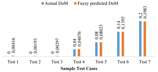
The DoM at different operating speed of rotating machine is predicted by using FIS. The output of FIS i.e. predicted DoM and actual values are compared as shown in Fig. 11. Also, it is clearly observed that DoM prediction with implemented Fuzzy Logic is in very precise limit as observed in Table 3. The minimum error is 0.01 % and maximum error is 0.85 %. The cumulative average error observed is less than one percent. This shows an effective implementation of Fuzzy Logic for prediction of DoM. It has reasonably succeeded in prediction of degree of misalignment with high accuracy.
Fig. 11Comparison between actual and predicted DoM
The speed range considered for prediction of DoM values can be obtained without changing range of input membership functions, output membership functions and fuzzy rules as vibration signals are normalized using Eq. (1), Eq. (2) and Eq. (3). Performance of DFMP method has been verified at different operating speed and it is observed that the proposed DFMP method is very effective to predict DoM. The present study is an important attempt in developing a tool which is useful in exploring prediction of misalignment.
7. Conclusions
It is clear from literature review that research on misalignment has been focused majorly with FFT or orbit analysis like technique where output vibration signal analysis is done, and results are predicted where fault information in non-stationary signal is not retrieved. Sometimes confusing description of harmonics generated is agreed in misalignment analysis. The 1X, 2X harmonic response is common consideration of presence of misalignment. It is seen that results obtained in misalignment prediction by combined approach of DWT with FIS are in close agreement with least deviation. Hence, an implementation of combined Discrete Wavelet Transform and Fuzzy Logic is done successfully. Fuzzy logic predicts very accurately precise values of DoM at variable speed conditions of rotating machineries. The selection of DB2 mother wavelet is in close tally with feature evaluated. It is seen that an average error encored in output result is less than 1 % for vibration signal analysis with this combined approach. Hence, this approach can be successfully implemented to predict degree of misalignment in majority of rotating machine condition monitoring. Continuous monitoring in run time condition is possible with FIS built in application.
References
-
Bognatz S. R. Alignment of critical and non-critical machines. Orbit, Vol. 4, 1995, p. 23-25.
-
Wowk Victor Machine Vibration: Alignment. 2nd Ed., Mc-Graw Hill Publications, 2000.
-
Ubale R., Dhumale R. B., Lokhande S. D. Open switch fault diagnosis in three phase inverter using diagnostic variable method. International Journal of Research in Engineering and Technology, Vol. 2, Issue 12, 2013, p. 636-640.
-
Lalit Patil, Dhumale R. B., Lokhande S. D. Fault detection and diagnosis technique for power inverter using discrete wavelet transform. International Journal of Electronics Circuits and Systems, Vol. 3, Issue 2, 2014, p. 174-178.
-
Ubale M. R., Dhumale R. B., Lokhande S. D. Method of open switch fault detection in three phase inverter using artificial neural network. International Journal of Research in Science and Advance Technology, Vol. 3, Issue 3, 2014, p. 78-82.
-
Dhumale R. B., Lokhande S. D., Thombare N. D., Ghatule M. P. Fault detection and diagnosis of high speed switching devices in power converters. International Journal of Research in Engineering and Technology, Vol. 4, Issue 2, 2014, p. 253-257.
-
Dhumale R. B., Lokhande S. D. Diagnosis of multiple open switch faults in three phase voltage source inverter. Journal of Intelligent and Fuzzy Systems, Vol. 30, Issue 4, 2016, p. 2055-2065.
-
Dhumale R. B., Lokhande S. D. Neural network fault diagnosis of voltage source inverter under variable load conditions at different frequencies. Measurement, Vol. 91, 2016, p. 565-575.
-
Dhumale R. B., Lokhande S. D. Condition monitoring of voltage source inverter. International Journal of Emerging Trends in Electrical and Electronics, Vol. 11, Issue 6, 2015, p. 21-26.
-
Alok Kumar, et al. Shaft misalignment detection using stator current monitoring. International Journal of Advanced Computer Research, Vol. 3, Issue 8, 2013, p. 305-309.
-
Al Badour F., Sunar M., et al. Vibration analysis of rotating machinery using time frequency analysis and wavelet techniques. Mechanical Systems and Signal Processing, Vol. 25, Issue 6, 2011, p. 2083-2101.
-
Tanks Oliver, Wang Qing The detection of wind turbine shaft misalignment using temperature monitoring. CIRP Journal of Manufacturing Science and Technology, Vol. 17, 2017, p. 71-79.
-
Simm Anthony, Wang Qing, et al. Laser based measurement for the monitoring of shaft misalignment. Measurement, Vol. 87, 2016, p. 104-116.
-
Arebi L., et al. A Comparative Study of Misalignment Detection Using Novel Wireless Sensor with Conventional Wired Sensor. IOP publishing, Huddersfield, UK, 2012.
-
Prabhu B. S., Sekhar A. S. Effects of coupling misalignment on vibrations of rotating machinery. Journal of Sound and Vibrations, Vol. 185, Issue 4, 1995, p. 655-671.
-
Bossio Jose M., et al. Angular misalignment in induction motor with flexible coupling. 35th Annual Conference of IEEE Industrial Electronics, 2009.
-
Tejas Patel, Ashish Darpe Vibration response of misalignment rotors. Journal of Sound and Vibration, Vol. 325, Issue 3, 2009, p. 609-628.
-
Dewell D. L., Mitchell L. D. Detection of misaligned disk coupling using spectrum analysis. Journal of Vibration, Acoustic, Stress and Reliability in Design, Vol. 106, Issue 1, 1984, p. 9-16.
-
Saavedra P. N., Ramirez D. F. Vibration analysis of rotors for the identification of shaft misalignment, part I and II. Journal of Mechanical Engineering science, Vol. 218, Issue 9, 2004, p. 987-999.
-
Huang Diangui Characteristics of torsional vibrations of a shaft system with parallel misalignment. Proceeding of Mechanical Engineering science, Vol. 219, Issue 11, 2005, p. 1219-1224.
-
Bhave S. Y., et al. Vibration signature due to shaft misalignment. Conference Proceeding IAT, 1982.
-
Umbrajkaar Amit, Krishnamoorthy A. Modelling and vibration analysis of shaft misalignment. International Journal of Pure and Applied Mathematics, Vol. 114, Issue 11, 2017, p. 313-323.
-
Watson Simon J., et al. Condition monitoring of the power output of wind turbine generators using wavelets. IEEE Transactions on Energy Conversion, Vol. 25, Issue 3, 2010, p. 715-721.
-
Mahdi Mousavi S., Aida Mollaeian A novel parallel modelling wavelet based mechanical fault detection using stator current signature of induction machine under variable load conditions. Journal of Electrical Engineering and Electronic Technology, Vol. 6, Issue 2, 2017, https://doi.org/10.4172/2325-9833.1000143.
-
Pratesh Jayaswal, Verma S. N., Wadhwani A. K. Application of ANN, fuzzy logic and wavelet transform in machine fault diagnosis using vibration signal analysis. Journal of Quality in Maintenance Engineering, Vol. 16, Issue 2, 2010, p. 190-213.
-
Li Xiaoli, Tso Shiu Kit Real-time tool condition monitoring using wavelet transforms and fuzzy technique. IEEE Transactions on Systems, Man, and Cybernetics, Part C (Applications and Reviews), Vol. 30, Issue 3, 2000, p. 352-357.
-
Zhou Jianzhong, Xiao Han, Li Chaoshun Shaft orbit identification for rotating machinery basedbon statistical Fuzzy vector chain code and support vector machine. Journal of Vibroengineering, Vol. 16, Issue 2, 2014, p. 713-724.
-
Sanjeevkumar P., Febin Daya Wavelet transform with fuzzy tuning based indirect field oriental speed control of three phase induction motor drive. International Conference Electrical Drives and Power Electronics, 2015.

