Abstract
It is possible to reduce personnel, vehicle cargo security, and cost with a vehicle tracking system. Algorithm and architecture were created using open source code programs, and elements such as software, cost efficiency, personal security, efficient fleet management, and time savings were measured. In the study, it is aimed to develop the existing systems by considering the plus and minus aspects of vehicle tracking systems. It was emphasized that the system was easy to apply, and low cost and comparisons were made with the advantages and disadvantages of the system. The most critical factor in fleet management is vehicle tracking systems. In our study, the problem was studied with a mechatronic system approach, open to development, and analytical approach. The system has been developed as a modular structure that is easily integrated into existing infrastructures. With the system created, it was aimed to increase the working efficiency of the company vehicles, to provide optimum solutions for vehicle maintenance processes, and to save fuel and time, by considering the safety of the driver.
1. Introduction
In recent years, vehicle tracking systems (ATS) have become widespread, especially in parallel with the developments in internet technology. The global positioning system (GPS), which was previously used in corporate applications, has become a part of our daily lives with the developing technology. Today, thanks to the size of GPS receivers placed in mobile phones, all segments of the society had the opportunity to meet with GPS technology [1]. ATSs determine the location of the vehicle using GPS technology and provide the easiest, most economical, and safest way to reach the planned routes [2, 3]. Initially, ATS devices, which were quite large, were reduced to smaller dimensions in parallel with the rapid development of technology. In this way, it has begun to be used in the monitoring of people and even animals [4].
In scientific studies started in the 2000s on this subject; In an ATS design supported by the World Wide Web (WEB) based on General Pocket Radio Service (GPRS), the GPRS server was connected to the internet and monitoring was performed on the digital map [5]. In another WEB-based vehicle tracking management system design, WEB services were used to process and display the data transferred to the GPRS server.
In addition, it was enabled to monitor via Personal Digital Assistant (PDA) [6]. In another WEB-based ATS, the location information of the vehicle tracking device is sent to the GPRS server via Short Message Service (SMS). There is an emergency button on the device, and alarm notification is provided in case of danger [7]. In the design of a WEB-based vehicle tracking management system, Global System for Mobile (GSM) base station information is transmitted along with the location information. If GPS information is interrupted, base station information is used in these systems.
Tracking of vehicles is provided over the internet with Google maps [8]. In a study, it is stated that if GPS receivers are located in closed areas, it is not possible to calculate the location because the GPS signal cannot be obtained [9]. In another study, the design and construction of a personal computer-based vehicle tracking system over GSM and the Map-Info-based digital map are integrated into the vehicle tracking software [10]. In this study, a vehicle tracking system, which can be connected to the Can-Bus (CB) communication protocol in the equipment of the vehicles, has been created. The data are taken from the vehicle's CB system and transferred to a receiver via a wireless connection and collected. Central data transfer points are determined as the lines or waiting places used by the vehicles. When vehicles arrive at these stations, data is collected, and a report is generated. The reports are designed with a simple interface. User restrictions can be made for reporting. Alarm conditions can be seen on the report screen, and the driver can be warned. It can also track fuel-performance relationship and driver behavior in the vehicle. In addition, other parameters listed above can also be delivered to those designated as digital messages. Authorities can provide feedback to the driver via the report screen. With this control and observation system, physical injuries such as vehicle information, vehicle wear, maintenance, fuel-saving, and any physical disruption to the vehicle can be prevented.
2. Material and method
Can-Bus system (Fig. 1.) German Bosch electrical electronics company started work on CB in 1983. After completing their work, they announced the CB system at the “Society of Automotive Engineers” conference in 1986. The CB communication protocol is the communication standard developed by Bosch for automotive. It provides communication between the brains and sensors on the vehicle. Today, it is a communication protocol that is widely used not only in the automotive industry but also in other industrial areas. It stands for “Controller Area Network BUS”, that is, “Control Area Network Bus” [11].
Fig. 1CB communication system [12]
![CB communication system [12]](https://static-01.extrica.com/articles/21471/21471-img1.jpg)
The information we have accessed through the CAN line enables it to be transferred to the vehicle tracking device. This information transferred to the vehicle tracking device is arranged as an interface to be presented to the users. We can obtain many vehicle data such as instant fuel consumption, total fuel consumption, immediate changes in fuel level, total vehicle mileage, instantaneous vehicle speed, axle weight, engine temperature, service mileage, fault codes with the CB communication protocol. The data we receive on the vehicle varies according to the brand, model, and year of manufacture. The data available from the vehicle are as follows:
– Transfer information.
– Instant fuel consumption.
– Remaining fuel amount.
– Average fuel amount.
– Oil condition.
– Failure and warning information.
– Engine condition, temperature.
To make the connections easily, a development card named Nodemcu, which is shown in Fig. 2, has been created. This board can be connected to the computer with a USB cable and installed directly on the program with Arduino. In addition, the card can be updated with remote access software. Arduino libraries were transferred on ESP8266. It is also possible to develop programs with many different programming languages such as Python, LUA, C/C ++.
Fig. 2Nodemcu development card [13]
![Nodemcu development card [13]](https://static-01.extrica.com/articles/21471/21471-img2.jpg)
2.1. Embedded system features
An embedded system is used for the prepaid system. It is a module that provides low cost, wireless network connection, and includes TCP/IP support. With a direct wireless connection (P2P), soft-AP can be installed. The most important feature of this module is that it can be used both as a server and as a client. Supporting IEEE 802.11 b/g/n standards, the module’s specifications support many communication protocols. In this way, it also allows the data from different microcontrollers to be transmitted. There is also 10-bit analog input and serial. It can be connected to the wireless internet network through communication. ESP8266 features are as follows:
– 802.11 b/g/n.
– Wi-Fi Direct (P2P), soft-AP.
– Integrated TCP / IP protocol stack.
– Integrated PLLs, regulators DCXO and power distribution units.
– Outputs + 19.5dBm in 802.11b mode.
– Can be used in low power 32-bit CPU processor applications.
– SDIO 1.1/2.0, SPI, UART.
– Opening and packet transfer time < 2 ms.
– Standby power consumption < 1.0 mW.
Arduino compiler was used to program the microcontroller ESP8266 on the Nodemcu Wi-Fi development board. In order to use the Arduino compiler, ESP8266 libraries are installed to communicate with the Arduino kernel and the CB module. By looking at the libraries, the software to be used was determined by examining the keywords and software examples. With the advancement of computer technology and more and more entering our lives, much different software is being developed. Various interfaces are designed on both mobile devices and computers. It is also essential to identify the most useful interfaces and indicate the advantages and disadvantages of these interfaces. The quality of service that is important in the interface design, which we can consider as a bridge that provides communication between the computer and the user, is. It can be used easily from the current updates of the current browsers. A front face prepared with the marking language suitable for this structure can be created.
This study was created with the Python programming language. Python is an object-oriented, interpretive, modular, and interactive, high-level language. Python is an interpretive language, meaning, unlike words such as C and C++, it can be run without compiling. Via the interface created as a result of the project, information such as license plate number, driver information, speed, location, seat belt information, fuel consumption, tracked route, and target distance can be followed as external data.
If there are violations, these violations are shown in red. Warnings and sanctions of these violations can be sent to the responsible person in the company either as a report or as a warning to the user through this interface. The contact information of the user is also available on this system
3. Experimental studies
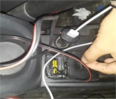
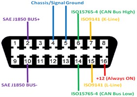
In the study, the location of the vehicle’s Onboard Diagnostics (OBD) socket should be determined. The location of this socket may differ in vehicle brands. The connection diagram of the OBD socket location and pin distribution is shown in Fig. 3. At this stage, it is essential to determine the CB-High and CB-Low outputs correctly.
Fig. 3OBD socket information and pin distribution


The correct connection to the CB module and the baud rate of the vehicle must be selected correctly. For our sample tool, this value is 500 kbps. The energy of the blade is provided from the charge input of the vehicle with the help of Universal Serial Bus (USB) cable, and alternatively, power can be obtained from the 16th pin of the OBD socket. Data exchange is provided by communicating with the CB module over the Nodemcu Wireless card (Fig. 4) through the SPI interface.
Fig. 4Nodemcu CB Module Connection [13]
![Nodemcu CB Module Connection [13]](https://static-01.extrica.com/articles/21471/21471-img5.jpg)
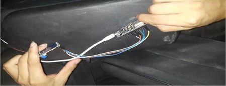
Fig. 5Nodemcu CB module connection application

The system is prepared by connecting the CB module to the CB-High, and CB-Low ends. (Fig. 5). The Nodemcu module was connected to the computer wirelessly, and the data was transmitted to the server.
4. Conclusions
The project has successfully passed the necessary stages, and recorded documents such as picture videos have been created. The CB module provided an accurate reading of the information, and the Esp8266 wireless module transmits this information completely. This information can be easily read in the designed interface, and an alarm can be sent by e-mail when necessary. Data systems are used in such systems. In this system, the vehicle tracking system was created by saving costs instead of this card. Although data cannot be obtained instantly, desired reporting and results can be obtained, and control is provided. Considering the requests of the users, the cost reduction can be important in terms of performance relation and can be the reason for preference.
The system is very economical in terms of hardware cost. Reporting can be monitored on an easy interface. Notifications are made in real-time and provide feedback. The system does not affect vehicle design, and it is seen that it does not cause an electrical problem. However, the system requires a GPS positioning feature for instant location determination and increases this cost. Therefore, instant location tracking is not possible. Instant data flow cannot be provided; only accumulated data can be used. Different coding is required for each vehicle type.
References
-
Uylu K. GPS Assisted Vehicle Navigation Systems Design. İ.T.Ü Fen Bilimleri Enstitüsü, Turkey, 2006.
-
Çivril Ö. Tracking Vehicles’ Positions and Movements on the Digital Maps with the Help of Satellites. Pamukkale Üniversitesi Fen Bilimleri Enstitüsü, Denizli, Turkey, 2011.
-
Ersoy S., Ertugrul I., Aygul E. The methods used in the automotive production: hemming operations planning. Marriage, Vol. 10, Issue 13, 2015, p. 12-25.
-
Jain V. R., Bagree R., Kumar A., Ranjan P. GPS based animal tracking system. Intelligent Sensors, Sensor Networks and Information Processing, 2009.
-
Giralda D. B., Anton Rodrigez M., Diaz Pernas F.-J., Diez J. F. Intelligent system for dynamic transport fleet management. Proceedings of 10th IEEE International Conference on Emerging Technologies and Factory Automation, 2005.
-
Goulas G. A. Helicopter taxi company software support system based on GPS, GSM and web services. IEEE Conference on Emerging Technologies and Factory Automation, 2006, p. 1107-1114.
-
Liu Q., Lu H., Zhang H., Zou B. Research and design of intelligent vehicle monitoring system based on GPS/GSM. 6th International Conference on ITS Telecommunications, Vol. 12, Issue 1, 2016, p. 1267-1270.
-
Thong S. T., Han C. T., Rahman T. A. Intelligent fleet management system with concurrent GPS and GSM real-time positioning technology. 7th International Conference on ITS Telecommunications, 2007.
-
Kaplan E. D., Hegarty C. Understanding GPS: Principles and Applications. Second Edition, Artech House, Norwood, 2005.
-
Balcılar M. PC Based Vehicle Tracking System Design and Construction Over GSM. Gazi Üniversitesi Fen Bİlimleri Enstitüsü, Ankara, Turkey, 2010.
-
Ersoy S. Vehicle security systems. Makina İmalat ve Teknoloji Kültürü Dergisi, Vol. 10, Issue 2, 2006, p. 58-64.
-
Emerich A. CAN Newsletter Magazine. https://can-newsletter.org/tools/tools-miscellaneous/140925_kickstarter-campaign-for-hacking-cars_canbus-triple_kuschel, 2019.
-
Koyanagi F. MCU ESP8266: Details and Pinout. https://www.instructables.com/id/ NodeMCU-ESP8266-Details-and-Pinout, 2019.

