Abstract
In order to solve the problem of accurate vehicle path tracking and address the issues of low convergence accuracy and susceptibility to local optima in Whale Optimization Algorithm (WOA), a nonlinear convergence factor is proposed and nonlinear inertia weights are introduced to improve the basic WOA. Firstly, the convergence factor in WOA is changed to a nonlinear convergence factor, and a nonlinear inertia weight is introduced to improve the convergence accuracy, local development ability, and global search ability. Then, this algorithm is combined with a fifth-degree polynomial. The simulation results show that the proposed method can solve the problem of vehicle path tracking effectively. And also, the vehicle can track the given path controlled by the proposed algorithm with higher accuracy and has stronger applicability. The study can help drivers easily identify safe lane-changing trajectories and area.
Highlights
- The proposed method can solve the problem of vehicle path tracking effectivelly.
- The vehicle can track the given path controlled by the proposed algorithm with higher accuracy and has stronger applicability.
- The study can help drivers easily identify safe lane-changing trajectories and area.
1. Introduction
In the past few decades, autonomous driving technology has developed rapidly. In the next 30 years, more and more intelligent vehicles will operate on public roads, which will allow enhancing the country's technological strength but also helping to alleviate urban traffic congestion. Motion planning is a very important role in intelligent vehicles. Appropriate motion planning algorithms can significantly reduce traffic accidents caused by driver’s fatigue or drunken condition. Research on trajectory generation has been ongoing for many years. The purpose of path algorithm research is to ensure that the vehicle can accurately track the reference path and ensure the vehicle driving stability and riding safety during the path tracking process. In recent years, fruitful research achievements were obtained in path tracking control algorithms, and many scholars optimized and innovated the existing algorithms. The goal of path tracking is to make the controlled vehicle travel along the expected path while ensuring the driving stability. A significant increase in the number of vehicles brought about a series of problems such as traffic congestion and safety accidents. And the main influencing factors, such as driver’s physical condition, psychological state, and improper driving skills, are human factors and depend on the current driver’s condition. Autonomous vehicle can transfer and share driving responsibilities, greatly reducing the probability of traffic accidents caused by such human factors. Path tracking control also became a hot topic of concern and research for scholars in the recent years. Path tracking control refers to the use of automatic steering control to ensure that the vehicle always follows the desired path while ensuring the driving safety and comfort. Due to the nonlinear and strong coupling characteristics of automobiles, their lateral and longitudinal movements are highly coupled, making it difficult for vehicles to ensure both path tracking accuracy and driving stability [1, 2].
Zhou et al. proposed a trajectory tracking control method for the tractor-trailer wheeled robot [3]. Song et al. studied a guidance and control framework of multiple autonomous surface underwater vehicles (multi-ASUV) based on deep reinforcement learning (DRL) for target tracking [4]. Miao et al. presented a new robust path-following (PF) control method for underactuated marine vehicles with multiple disturbances and constraints [5]. Wang et al. studied the problem of path tracking at Autonomous Ground Vehicles (AGVs) in the presence of sideslip angles [6]. Rath et al. proposed a robust model predictive controller for accomplishing an effective path following motion plan of an Autonomous Underwater Vehicle in face of uncertainties, external disturbances, and actuator constraints [7]. Murillo et al. presented a novel non-linear mathematical model of an articulated tractor-trailer system [8]. He et al. took a paddy field agricultural machinery body as the control object and established an agricultural machinery kinematics model based on the agricultural machinery pose correction [9]. Chen et al. presented an ant colony system-based algorithm to obtain good enough paths for unmanned aerial vehicles and fully covered all regions efficiently [10]. Zhu et al. proposed a novel cross-camera tracking method for vehicle loads by using deep metric learning and edge computing [11]. Sabiha et al. investigated the trajectory tracking control of an autonomous tracked vehicle [12]. Wang et al. proposed an optimal trajectory-tracking guidance method for Reusable Launch Vehicle (RLV) based on the neural Adaptive Dynamic Programming (ADP) [13]. Morais et al. proposed a robust recursive controller designed via multi-objective optimization [14].
Although many researchers are conducting theoretical and applied research, there are still many problems in vehicle path tracking. Although the frequency domain method can be used to solve the vehicle path tracking problem, it has many limitations when applied to transient responses. The time domain method is more sensitive to the boundary conditions and initial value conditions of an automobile’s motion. Moreover, its conversion accuracy is not ideal, and its stability and robustness need to be improved. Although the WOA has advantages such as fewer parameters and a simple structure, it is prone to getting stuck in local optimal solution and has low convergence accuracy. In order to obtain more accurate trajectory optimization results, this paper proposes a nonlinear convergence factor and introduces a nonlinear inertia weight to address the shortcomings of the WOA and meet the performance requirements of automotive trajectory tracking which can improve global search ability, convergence accuracy and speed.
2. Mathematical model of vehicle path tracking problem
2.1. Mathematical model of vehicle path tracking problem
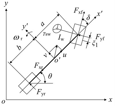
A nonlinear 4-DOF vehicle model shown in Fig. 1 is used to describe the vehicle path tracking problem.
In the state space form, is the equation is as follows:
The state variable is and the control variable is . Then Eq. (2) can be obtained by simplifying Eq. (1):
Fig. 14-DOF vehicle model
2.2. Optimal control object of path tracking problem
The minimum time required to complete the path tracking process is determined as the control object.
The cost function is:
where is the initial time, is the final time.
2.3. Tire model
The lateral forces of front and rear wheels can be expressed as (Eq. 4) [19]:
where and are the lateral stiffness values of the front and rear tires. and are the front and rear slip angles:
2.4. Constrains
The initial and terminal states are described as:
When the braking maneuver is applied to decelerate the vehicle, the constraints on , can be rewritten in the following manner:
So, the optimal path tracking problem can be described as:
where expresses the inequality constraint.
3. Whale optimization algorithm
WOA is a new meta-heuristic algorithm proposed by Seyedali Mirjalili and Andrew Lewis [16], which simulates the spiral hunting pattern of humpback whales searching for prey. The search space is approximated as a cone, the search path is approximated as a spiral line that rises around the surface of the cone, and the current optimal individual and target positions are approximated as two points. A spatial model is established as shown in Fig. 1. The process of humpback whales hunting on prey is divided into processes: 1) encircling the prey (i.e. reducing the search space), 2) contracting the encirclement (i.e. spiral update of the position), and prey search (i.e. target searching). Mathematical models are established for each of the three predatory stages mentioned above.
3.1. Search space reduction
When a humpback whale population searches for prey in a certain search space, the nearest humpback whale (the optimal individual) will gradually approach the prey through a random path from its current position, and other humpback whales in the population will use the optimal individual as a close target to approach the prey indirectly. When establishing a mathematical model, the optimal individual pair in the population is equal to the current optimal solution. In the WOA, it is assumed that the number of humpback whale populations is and the search space is D-dimensional, the mathematical form describing this predatory behavior is:
where is the current number of iterations; is the updated location; is the current optimum position; is the difference between the optimal solution and the individual whale; and are the coefficient vectors:
where and are the random vectors in [0, 1]; is the maximum number of iterations; is the convergence factor. As the number of iterations increases, it decreases linearly from 2 to 0, and its expression is:
3.2. Spiral position updating
Humpback whales adopt a spiral contraction and encirclement method during their predation, meaning that their position updates in a spiral pattern. Applying this behavior to the algorithm, the mathematical model of spiral predation behavior is established as follows:
Due to the simultaneous contraction and spiral ascent behavior of humpback whales, it is necessary to consider which iteration method to use when updating their position. At this point, the probability p is used as the assessment threshold, and the corresponding iteration method is selected based on different probability values. The specific expression is as follows:
where is the random vectors in [0, 1]; is the constant that defines the logarithmic spiral shape; l is the random vectors in [–1, 1].
3.3. Target Search
The above two stages are based on the premise of detecting the prey location (i.e. ). If the relevant information about the prey has not been found (i.e. ), humpback whales need to search for prey through different random methods. This process takes place at the target search stage, and the mathematical expression shall take the following form:
where is the randomly selected whale individuals in the population for the current iteration.
4. Improved WOA
4.1. Inertial weights introduction
In order to improve the local development ability and convergence accuracy of WOA, the idea of inertia weight is usually introduced into the algorithm. However, linearly changing inertia weights cannot achieve good results in actual iterations. Therefore, a nonlinear inertia weight proposed in [17] is introduced, and the expression is as follows:
where is the constant coefficient set as 0.01. At this point, the inertia weight decreases nonlinearly as the number of iterations increases.
4.2. Addition of nonlinear convergence factors
In the mathematical model of basic WOA, the global exploration ability is mainly influenced by parameter . And the parameter that affects is the convergence factor . To improve the global search ability of WOA, it is necessary to modify the convergence factor . Due to the linear convergence of in basic WOA, it is easy for WOA to fall into local optima in global search, resulting in inaccurate calculation results. In order to ensure that the rate of convergence in the early stage of the iteration is fast, and the convergence accuracy in the later stage is high in the actual optimization process, a nonlinear convergence factor is proposed, and the expression is as follows:
where is nonlinear and increasing, and has a fast convergence at the early stage, and a relatively slow rate of convergence at the later stage, which meets the convergence requirements of iterative optimization described in . Then the mathematical expression of individual position updating in the improved WOA can be summarized as:
When , the position updating formula should be expressed as:
4.3. MWOA algorithm steps
The basic steps of the algorithm are as follows:
Step 1. Set the population size as N and randomly generate the initial population position. The initialization parameters are , , , l, , , and the maximum iteration number is .
Step 2. Calculate the fitness value of each whale individual (i.e. search agent) in the population, select the humpback whale individual with the lowest fitness value, define it as the current optimal individual, and use to represent its position vector.
Step 3. In each iteration, update the relevant parameters of each search agent , , , l, , . If , the location update of each search agent is carried out by Eq. (20); Otherwise, calculate it according to Eq. (21).
Step 4. Compare the individuals in the updated population to determine the global optimal individual and current position.
Step 5. If the maximum number of iterations is reached, that is, the termination condition for the loop part in WOA is reached, obtain the output result; otherwise, return to Step 2 and continue the calculation until the termination condition is met.
The output result is the global optimal solution .
5. Numerical simulations and experimental verification
5.1. Numerical simulations
In order to verify the effectiveness of the algorithm for path tracking problem of vehicle, a simulation is established under lane changing condition with different speeds.
5.1.1. 40 km/h
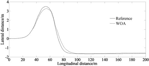
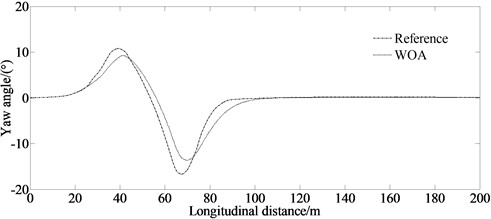
Fig. 2 contains the simulation result at the speed of 40 km/h. It can be seen from Fig. 2(a) that the vehicle can track the given path well under the control of the proposed algorithm. Fig. 2(b) indicates that there are peak values at 40 m and 65 m. This is because, when the vehicle enters and exits the corner, it needs a higher yaw angle to ensure the vehicle stability.
Fig. 2Simulation result under condition of 40 km/h
a) Lateral distance
b) Yaw angle
5.1.2. 80 km/h
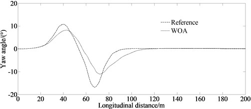
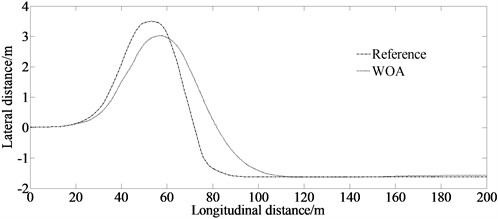
Fig. 3 contains the simulation result at the speed of 80 km/h. It can be seen from Fig. 3(a) that with the continuous increase of the vehicle speed, the error between the reference and the simulation becomes larger. However, the algorithm provided in this article still has a good control performance. From Fig. 3(b), it can be seen that there are peak values at 40 m and 70 m. This is because when the vehicle enters and exits the corner, it needs a higher yaw angle to ensure the vehicle stability. At the same time, the error between the reference and the simulation becomes larger.
Fig. 3Simulation result under condition of 80 km/h
a) Lateral distance
b) Yaw angle
5.2. Accuracy verification
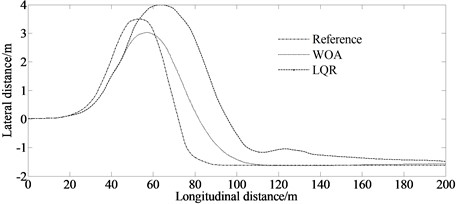
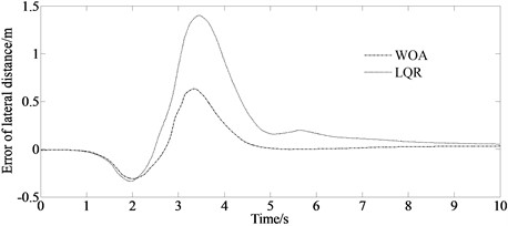
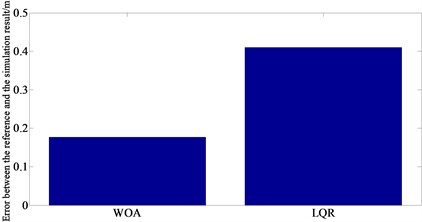
In order to verify the accuracy of the algorithm, a comparison between the traditional method and the proposed algorithm is considered.
Fig. 4 contains the result of accuracy verification. It shows that when tracking the same given path, the error between the reference and the simulation result of the WOA algorithm is smaller than that of the LQR method indicating at a higher calculation accuracy.
Fig. 4Accuracy verification
a) Lateral distance
b) Error of lateral distance
c) Error between reference and simulation result
5.3. Experimental verification
A virtual test adopting the Carsim software is conducted to verify the feasibility of the simulated results. Being a professional vehicle system simulation software, Carsim is the standard software in the vehicle industry adopted by numerous international automobile manufacturers and parts suppliers. Carsim adopts a system oriented parametric modeling method. Users only need to select each vehicle component module from the model database and configure the corresponding parameters as required to quickly complete the construction of a vehicle dynamics model. Carsim provided a variety of vehicle models including vehicles, light trucks and SUVs. The flow chart of simulation of Carsim is shown in Fig. 5.
From Fig. 6, it can be seen that for the lateral distance and the yaw angle, there are errors between the simulation and the virtual test values. The reason is that the model in the virtual test ignores the nonlinearity of the steering system and suspension system. However, the maximum value of mean error of the lateral distance and the yaw angle are 0.038 m and 0.018 degree respectively. The trend of the curves in Figs. 6(a)-(f) is enough to illustrate the correctness of the proposed method.
Fig. 5Flow chart of simulation of Carsim
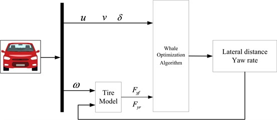
Fig. 6Experimental results of lateral distance and yaw angle
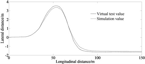
a) Lateral distance
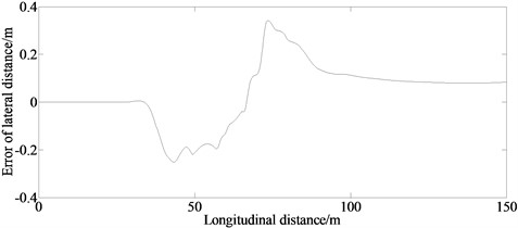
b) Error of lateral distance
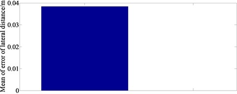
c) Mean error of lateral distance
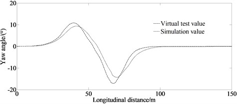
d) Yaw angle
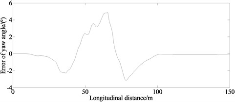
e) Error of yaw angle
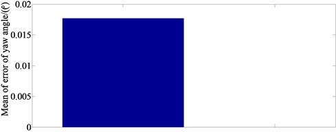
f) Mean error of yaw angle
6. Conclusions
To solve the problem of optimal vehicle path tracking, this paper establishes a Whale Optimization Algorithm improved by proposing a nonlinear convergence factor and introducing nonlinear inertia weights. Simulation and experimental results show that the proposed method has the advantage of high accuracy in solving the optimal path tracking control problem of the vehicle with multiple control variables and complex constraints, and can control the vehicle to complete the tracking of the given path at a high speed.
And also, this method can provide a reference for scholars to analyze the performance of overtaking and lane changing maneuverability of automobiles. However, this study did not consider the side-lane condition for autonomous vehicles. The collision avoidance of lane changes under various road conditions will be considered in future studies.
References
-
Y. Liu and D. Cui, “Vehicle state and parameter estimation based on double cubature Kalman filter algorithm,” Journal of Vibroengineering, Vol. 24, No. 5, pp. 936–951, Aug. 2022, https://doi.org/10.21595/jve.2022.22356
-
Y. Liu and D. Cui, “Vehicle state estimation based on adaptive fading Unscented Kalman filter,” Mathematical Problems in Engineering, Vol. 2022, pp. 1–11, Apr. 2022, https://doi.org/10.1155/2022/7355110
-
Y. Zhou and K.-W. Chung, “Path tracking control of a tractor-trailer wheeled robot kinematics with a passive steering angle,” Applied Mathematical Modelling, Vol. 109, pp. 341–357, Sep. 2022, https://doi.org/10.1016/j.apm.2022.04.025
-
D. Song, W. Gan, P. Yao, W. Zang, Z. Zhang, and X. Qu, “Guidance and control of autonomous surface underwater vehicles for target tracking in ocean environment by deep reinforcement learning,” Ocean Engineering, Vol. 250, p. 110947, Apr. 2022, https://doi.org/10.1016/j.oceaneng.2022.110947
-
J. Miao, X. Sun, C. Peng, and W. Liu, “DOPH∞-based path-following control for underactuated marine vehicles with multiple disturbances and constraints,” Ocean Engineering, Vol. 266, p. 113160, Dec. 2022, https://doi.org/10.1016/j.oceaneng.2022.113160
-
H. Wang, W. Song, Y. Liang, Q. Li, and D. Liang, “Observer-based finite frequency H∞ state-feedback control for autonomous ground vehicles,” ISA Transactions, Vol. 121, pp. 75–85, Feb. 2022, https://doi.org/10.1016/j.isatra.2021.03.027
-
B. N. Rath and B. Subudhi, “A robust model predictive path following controller for an autonomous underwater vehicle,” Ocean Engineering, Vol. 244, p. 110265, Jan. 2022, https://doi.org/10.1016/j.oceaneng.2021.110265
-
M. Murillo, G. Sánchez, N. Deniz, L. Genzelis, and L. Giovanini, “Improving path-tracking performance of an articulated tractor-trailer system using a non-linear kinematic model,” Computers and Electronics in Agriculture, Vol. 196, p. 106826, May 2022, https://doi.org/10.1016/j.compag.2022.106826
-
J. He et al., “Path tracking control method and performance test based on agricultural machinery pose correction,” Computers and Electronics in Agriculture, Vol. 200, p. 107185, Sep. 2022, https://doi.org/10.1016/j.compag.2022.107185
-
J. Chen, F. Ling, Y. Zhang, T. You, Y. Liu, and X. Du, “Coverage path planning of heterogeneous unmanned aerial vehicles based on ant colony system,” Swarm and Evolutionary Computation, Vol. 69, p. 101005, Mar. 2022, https://doi.org/10.1016/j.swevo.2021.101005
-
J. Zhu and X. Li, “Cross-camera tracking of vehicle loads based on deep metric learning and edge computing,” Measurement, Vol. 199, p. 111578, Aug. 2022, https://doi.org/10.1016/j.measurement.2022.111578
-
A. D. Sabiha, M. A. Kamel, E. Said, and W. M. Hussein, “ROS-based trajectory tracking control for autonomous tracked vehicle using optimized backstepping and sliding mode control,” Robotics and Autonomous Systems, Vol. 152, p. 104058, Jun. 2022, https://doi.org/10.1016/j.robot.2022.104058
-
X. Wang, Y. Li, Z. Quan, and J. Wu, “Optimal trajectory-tracking guidance for reusable launch vehicle based on adaptive dynamic programming,” Engineering Applications of Artificial Intelligence, Vol. 117, p. 105497, Jan. 2023, https://doi.org/10.1016/j.engappai.2022.105497
-
G. A. P. de Morais, L. B. Marcos, F. M. Barbosa, B. H. G. Barbosa, M. H. Terra, and V. Grassi, “Robust path-following control design of heavy vehicles based on multiobjective evolutionary optimization,” Expert Systems with Applications, Vol. 192, p. 116304, Apr. 2022, https://doi.org/10.1016/j.eswa.2021.116304
-
Y. Liu and J. Jiang, “Optimum path-tracking control for inverse problem of vehicle handling dynamics,” Journal of Mechanical Science and Technology, Vol. 30, No. 8, pp. 3433–3440, Aug. 2016, https://doi.org/10.1007/s12206-016-0701-9
-
S. Mirjalili and A. Lewis, “The whale optimization algorithm,” Advances in Engineering Software, Vol. 95, pp. 51–67, May 2016, https://doi.org/10.1016/j.advengsoft.2016.01.008
-
A. T. Sadiq, F. A. Raheem, and N. A. F. Abbas, “Robot arm trajectory planning optimization based on integration of particle swarm optimization and A* algorithm,” Journal of Computational and Theoretical Nanoscience, Vol. 16, No. 3, pp. 1046–1055, Mar. 2019, https://doi.org/10.1166/jctn.2019.7996
About this article
This research was supported by the Science and Technology Program Foundation of Weifang under Grant 2015GX007. And also, this research was financially supported by the Open Research Fund from the State Key Laboratory of Rolling and Automation, Northeastern University, under Grant 2021RALKFKT008. The first author gratefully acknowledges the supporting agencies.
The datasets generated during and/or analyzed during the current study are available from the corresponding author on reasonable request.
Fang Han: mathematical model and the simulation techniques. Yingjie Liu: spelling and grammar checking as well as virtual validation. Wen Peng: experimental validation.
The authors declare that they have no conflict of interest.
