Abstract
Using the active suspension system of an electric vehicle driven by two rear in-wheel motors as the research object, a 14-degree of freedom coupled vehicle dynamic model is established. Based on the model, a dual-loop proportion integration differentiation controller based on the particle swarm algorithm is designed to control the active suspension in this paper. The designed controller can not only ease the vibration of the vehicle body from the road surface roughness and the unbalanced electromagnetic force but also can improve the ride comfort of the vehicle. To further verify the effectiveness of the control method, the control effect of the active suspension controller designed in this paper is compared with that of a passive suspension and a dual-loop proportion integration differentiation controller without the particle swarm algorithm. The results show that the vertical vibration acceleration, the roller angle and the pitch angle of the vehicle body are significantly improved with the dual-loop proportion integration differentiation controller based on the particle swarm algorithm. Compared with the passive suspension and the dual-loop proportion integration differentiation controller without the particle swarm algorithm, the improvement ratio of the vertical vibration acceleration is 20.92 % and 11.93 %, respectively; the roll angle improvement ratio can reach 57.23 % and 22.02 %, respectively; and the improvement ratio of the pitch angle is 30.23 % and 18.94 %, respectively. The comparison results show that the dual-loop proportion integration differentiation controller optimized with the particle swarm algorithm can better improve the ride comfort of the vehicle.
1. Introduction
The vehicle suspension system is a key component of improving the ride comfort and handling stability of vehicles [1]. During the running process, the active suspension can produce an expected active control force based on the road condition, movement state, and vehicle load, so that the active suspension is always in the best working condition to improve the ride comfort and handling stability of the vehicle. Therefore, the control of active suspensions is an important development direction in the field of automobile suspension.
Designing the active suspension is the reasonable choice for the control method and strategy. At present, with the development of modern control theory and technology, more and more control methods have been applied to active suspension control, such as proportion integration differentiation (PID) control, optimal control, indistinct control, predictive control, neural network control, etc. [2-6]. In these control methods, PID control is widely used because of the simpler structure, stronger robustness and effective control. In [7], a single neuron PID control is used in the control of an active suspension system. In [8], a self-tuning PID controller is designed to control the active suspension. In [9, 10], the effectiveness of active suspension with a PID controller and a neural PID controller is verified based on the comparative analysis. The results show that the comprehensive performance of the active suspension controlled by the neural PID controller is better than that controlled by the PID controller. In [11], fuzzy and PID algorithms are combined and used in active suspension control. The results show that the integrated control algorithm is better than a controller with a single control algorithm. In [12], a PID controller with a self-adjusting parameter function is designed to control the active suspension and can improve the vehicle’s performance to some extent. In conclusion, the above studies were all designed on the basis of traditional vehicles using a single-loop PID structure to control the active suspension.
However, for the electric vehicle (EV) driven by in-wheel motors (IWMs), the excitation in the vertical direction acted on the vehicle is not only from the road surface roughness (RSR), but also from the electromagnetic force (EMF) produced by the motor magnet gap deformation which is caused by the RSR, uneven load, etc. [13].
Focusing on the issue above, a dual-loop active suspension control structure that is based on the particle swarm optimization (PSO) algorithm and PID control is proposed in this paper. The control structure is applied to the active suspension control of EVs to reduce the shock and the vibration of the vehicle body from the RSR and EMF and to improve the ride comfort of the vehicle. Furthermore, to verify the effectiveness of the control structure proposed in this paper, a passive suspension and a dual-loop PID controller without the PSO algorithm are compared.
2. Active suspension system model of the EV driven by IWM
2.1. Active suspension dynamic model
A rear IWMs drive EV is taken as the research object. The electric wheel structure is the form of direct drive without speed reducer, the detailed structure can be found in [14]. Fig. 1 shows the active suspension dynamic model of the whole vehicle. There are 14 degrees of freedom in the dynamic model, including one degree of freedom for the longitudinal movement of the vehicle, three degrees of freedom for the vertical, pitch, and roll movement of the vehicle body, six degrees of freedom for the vertical movement of the unsprung mass, and four degrees of freedom for the rotational movement of the wheels.
Fig. 114-degree of freedom dynamic model
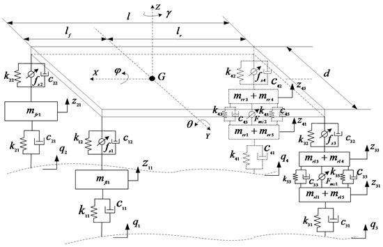
Using Newton’s Second Law, the mathematical model can be deduced based on Fig. 1:
The vertical displacement of the join point of vehicle body and the four suspensions can be deduced as:
Nonlinear of the adaptive suspension has been considered in the model, the nonlinear characteristics of the spring can be expressed as follow [15]:
When τ= 0, the spring is linear. Here, τ= 0.01.
For the damping coefficient, the nonlinear characteristics can be expressed as follow [16]:
2.2. RSR and EMF model
2.2.1. Mathematical model of the RSR
For the whole dynamic model with 14 degrees of freedom, four random RSR input signals are required to each wheel. Considering the RSR correlation among the four wheels in the space and time domain, the state equation of the four-wheel RSR input model can be expressed as follows [17]:
where:
˙Y(t)=[˙q1(t)˙q2(t)˙q3(t)˙q4(t)˙x1(t)˙x2(t)]T,
A=[a100000e-2πn00dud-ud0000-12ul+a100000e-2πn00dud-(12ul+ud)0001-12ul0000172u2l2000-12u2l2-6ul],
B0=[b10b1000]T,a1=-2πn00u,b1=2πn0√Sq(n0)u.
2.2.2. Mathematical model of the EMF
The air gap length of the IWM is the function of time t. The specific expression is as follows:
Transient air gap magnetic flux density is the synthetic magnetic flux density which is caused by the no-load air gap magnetic field generated by the permanent magnet and the armature reaction magnetic field generated by the three-phase stator winding, that is [18-21]:
Based on the Maxwell magnet stress tensor theory, the magnetic force density in the radial and tangential direction in 2-D magnetic field under polar coordinate can be calculated by:
Transforming the magnetic force density from the polar coordinates to Cartesian coordinate, the magnetic force density in X and Y direction is:
Considering the axial length of the IWM, the forces acting on the direction of X and Y of stator’s center can be obtained by the following integral:
3. Design of dual-loop PID controller based on PSO algorithm
3.1. Dual-loop PID control structure
Vehicle vibration in the vertical direction can be considered to consist of two parts: a part caused by the RSR and EMF excitation, and another part caused by the inertia of the sprung mass [22]. Aiming at these two parts of vibration, the dual-loop PID control structure that is shown in Fig. 2 is adopted to control the active suspension system.
Fig. 2Dual-loop PID control structure of active suspension
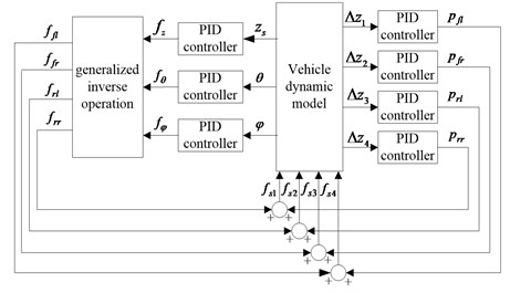
According to the control objective of active suspension, the deviation between the expected value and the actual value of the vertical acceleration, the pitch angle, the roll angle, and the suspension dynamic travel of the vehicle body is taken as the PID controller input.
For the inner loop controller, the deviation of the suspension dynamic travel ∆Zi (i=1, 2, 3, 4) between the expected and actual value is selected as the input variable of four PID controllers, and the suspension control force pj (j=fl, fr, rl, rr) is selected as the output variable to reduce the vibration caused by the RSR and EMF.
For the outer loop controller, the deviation between the expected and actual values of the vertical acceleration, the pitch angle, and the roll angle of the vehicle body is the PID controller input, and the control force (fz, fθ, and fφ) is selected as the output variable to reduce the vibration caused by the inertia of the sprung mass. According to the mechanical relationship between the vehicle body and suspension, the control force (fz, fθ, and fφ) can be expressed as:
By solving the generalized inverse matrix of H, the target control force of four suspensions fi (i=fl, fr, rl, rr) can be obtained:
Total control force of the suspensions is the superposition from the inner and outer loop controller, which can be expressed as:
3.2. Optimization of PID control parameters based on PSO algorithm
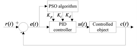
For the PID controller, the choice of control parameters Kp, Ki and Kd plays a significant role in the control effect. Generally, the appropriate selection of PID control parameters requires repeated debugs based on the designer’s experience; it is difficult to obtain the optimum value. Focusing on the above issue, the PSO algorithm is used in the dual-loop PID control structure to dynamically adjust the control parameters and to meet the optimal control effect. Fig. 3 shows the schematic of the PID controller with a PSO algorithm.
In this paper, the PSO algorithm with inertia weight coefficient is used for the PID parameter self-tuning and optimizing. In this algorithm, the speed and position of the particles can be updated as follows [23-24]:
Weight coefficient wk decides the search ability of the particles in the global and local range. To avoid “oscillating” phenomenon in the global optimal and local optimal solution when particles searching in the solution space, the weighting factor wk linearly reduces from the maximum wmax to the minimum weighted value wmin in the speed update formula, as shown in Eq. (18):
Fig. 3Schematic of PID controller with PSO algorithm
3.3. Optimization model of active suspension
3.3.1. Optimization objective function
Considering the driving dynamics of the whole vehicle, the vertical acceleration, the lateral angle, the pitch angle and the relative displacement of the IWM are chosen as the control objective. The weighting coefficient method is adopted to transform the multi-objective optimization problem into a single objective optimization problem. Additionally, to conquer the numerous inconsistent problems of the above control objectives, each control variable of the active suspension is divided by the corresponding passive suspension control variable. The optimization objective function is obtained as follows:
where σa(¨zs), σa(φ), σa(θ), σa(z33-z31) and σa(z43-z41) are the root mean square (RMS) value of the vertical acceleration, the roll angle, the pitch angel, the relative displacement between the stator and rotor of the left rear IWM and right rear IWM of the active suspension. σp(¨zs), σp(φ),σp(θ),σp(z33-z31) and σp(z43-z41) are the RMS value of the corresponding performance index of the passive suspension.
3.3.2. Constraint condition
Suspension dynamic travel: The allowable limited travel [fd] of the suspension is the maximum compression travel from the balance position of the vehicle body. The suspension dynamic travel and limit travel should be appropriately, otherwise the collision probability between the frame and the axle block will be increased in the driving process. The constraint condition about the suspension dynamic travel can be expressed as:
where σ(z1-z11), σ(z2-z21), σ(z3-z33) and σ(z4-z43) are the RMS of the left front, the right front, the left rear and the right rear suspension dynamic travel.
Tire dynamic load: To improve the stability and safety of the vehicle, the tire dynamic load should meet the following conditions:
where σ(Fdfl),σ(Fdfr), σ(Fdrl) and σ(Fdrr) are the RMS of the left front, the right front, the left rear and the right rear tire dynamic load. Gfl, Grl and Grr are the RMS of the left front, the right front, the left rear and the right rear tire static load.
According to the structural design requirements of the IWM, the relative displacement of the rotor and the stator should be satisfied with the following conditions:
where σ(z33-z31) and σ(z43-z41) are the RMS of the relative displacement of the left rear and right rear IWMs.
3.3.3. Optimization objective
Based on the optimization control objective and the constraint conditions above, the optimization problem in this study is a minimal design problem with constraint conditions. The optimization control problem can be formulated as:
s.t.
{g3(X)=σa(¨zs)-σp(¨zs)<0,g4(X)=σa(ϕ)-σp(ϕ)<0,g5(X)=σa(θ)-σp(θ)<0,g6(X)=σa(z1-z11)[fd]-13<0,g7(X)=σa(z2-z21)[fd]-13<0,g8(X)=σa(z3-z33)[fd]-13<0,g9(X)=σa(z4-z43)[fd]-13<0,g10(X)=σa(Fdfl)Gfl-13<0,g11(X)=σa(Fdfr)Gfr-13<0,g12(X)=σa(Fdrf)Grf-13<0,g13(X)=σa(Fdrr)Grr-13<0,g14(X)=σa(z33-z31)-0.001<0,g15(X)=σa(z43-z41)-0.001<0.
3.4. Dual-loop PID controller based on PSO algorithm
PSO, a type of swarm intelligent optimization algorithm, is put forward by a foraging act of research and observation about groups of birds. A PSO algorithm has the characteristics of good convergence and parallel global search; because of these characteristics, the algorithm can search the global optimal solution with a larger probability and effectively solve complex optimization problems [25-26]. Therefore, the PSO algorithm is used for PID parameter self-tuning and optimization in this paper. The optimization control process of the dual-loop PID controller based on the PSO algorithm is shown in Fig. 4.
Fig. 4Optimization control process of the dual-loop PID controller based on the PSO algorithm
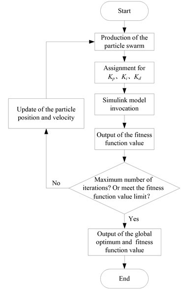
Table 1Vehicle parameters
Symbol | Unit | Value |
m | Kg | 1450 |
ms | Kg | 1160 |
Ix | Kg·m2 | 606 |
Iy | Kg·m2 | 1800 |
Ixz | Kg·m2 | 45 |
Iwi | Kg·m2 | 2.5 |
kj1 (j=1, 2, 3, 4) | N/m | 200000 |
cj1 (j=1, 2, 3, 4) | N/(m/s) | 100 |
kj2 (j=1, 2) | N/m | 35000 |
kj2 (j=3, 4) | N/m | 40000 |
cj2 (j=1, 2) | N/(m/s) | 1500 |
cj2 (j=3, 4) | N/(m/s) | 1800 |
ηj (j=1, 2) | – | 0.4 |
ηj (j=3, 4) | – | 0.32 |
n | – | 0.33 |
k33, k43, k35, k45 | N/m | 5000000 |
lf | m | 1.2 |
lr | m | 1.4 |
d | m | 1.44 |
hs | m | 0.488 |
rt | m | 0.3 |
4. Simulation and result analysis
4.1. Vehicle parameters
The vehicle parameters are summarized in Table 1, and the IWM parameters are shown in Table 2.
According to the Eqs. (3-5), the nonlinear characteristic of the suspension is shown in Fig. 5.
Table 2IWM parameters
Item | Symbol | Unit | Value |
Magnet gap thickness | g0 | mm | 1.5 |
Rotor inner radius | rri | mm | 229 |
Constant magnet thickness | hm | mm | 6 |
Remanence | BT | T | 0.98 |
Slot number | Qs | – | 36 |
Magnetic polar number | p | – | 6 |
Fig. 5Nonlinear characteristic of the suspension
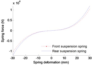
a) Nonlinear stiffness characteristic
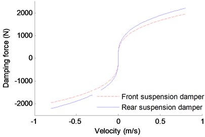
b) Nonlinear damping characteristic
4.2. Simulation and result analysis
Assuming that the vehicle runs on the road of B-class, and the vehicle speed is kept at 20 m/s. For the PSO algorithm, parameter selection is critical for the algorithm efficiency. At present, the selection of the parameters mostly relies on the experience and the test. So far, many researchers have made a body of studies and have gained great achievements on the PSO parameter selection [27-28]. Based on the previous works and several tests, the key PSO parameters are set as shown in Table 3.
Table 3PSO parameters
Parameter | Value |
Particle number | 100 |
wmin | 0.4 |
wmax | 0.9 |
c1 | 2 |
c2 | 2 |
kmax | 100 |
In order to verify the effectiveness of the control structure proposed in this paper, a dual-loop PID controller without the PSO algorithm and a passive suspension are adopted to control the vehicle dynamics at the same conditions. Fig. 6 shows the contrast control results of the vertical acceleration, the lateral angle, the pitch angle and the relative displacement. Here, the weight coefficient of each index in the simulation is: λ1= 0.4, λ2= 0.2, λ3= 0.2, λ4=λ5=0.1.
To make a better comparison over the three control methods, statistical analysis of the above figures are carried out, and the RMS value of each performance indexes is shown in Table 4.
Table 4RMS value of the performance index using different control method
RMS value | Passive suspension | Dual-loop PID control | Dual-loop PID with PSO control |
Vertical acceleration (m/s2) | 1.1019 | 0.9894 | 0.8714 |
Roll angle (°) | 0.2343 | 0.1285 | 0.1002 |
Pitch angle (°) | 0.1343 | 0.1156 | 0.0937 |
Relative displacement of the left rear IWM (mm) | 7.8717e-2 | 7.8655e-2 | 7.8361e-2 |
Relative displacement of the right rear IWM (mm) | 7.9454e-2 | 7.8945e-2 | 7.8468e-2 |
As shown in Fig. 6 and Table 4, compared with the passive suspension and the dual-loop PID control without the PSO, the vertical vibration acceleration, the roll angle and the pitch angle of the vehicle body using dual-loop PID control with PSO have significant improvement, and the relative displacement of the IWM rotor and the stator has some improvement. Ratio of the difference between the index’s RMS obtained from the passive suspension method (or dual-loop PID control) and the dual-loop PID with PSO control method to the index’s RMS obtained from the passive suspension method (or dual-loop PID control) is used to indicate the improving degree of the performance index obtained from the control method proposed in this paper. And the calculation results show that, compared to the passive suspension and the dual-loop PID control without the PSO, the improvement ratio of the vertical vibration acceleration is 20.92 % and 11.93 %, respectively, the roll angle improvement ratio can reach 57.23 % and 22.02 %, respectively, and the improvement ratio of the pitch angle is 30.23 % and 18.94 %, respectively. Therefore, the dual-loop PID controller with PSO designed in this paper has good improvement for the ride comfort of EVs driven by IWMs.
Fig. 6Comparison result of the different control method
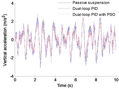
a) Vertical acceleration
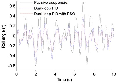
b) Roll angle
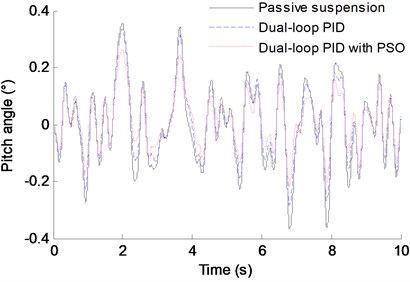
c) Pitch angle
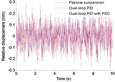
d) Relative displacement of the left rear IWM
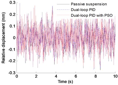
e) Relative displacement of the right rear IWM
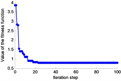
The iterative process of the controller is shown in Fig. 7.
As shown in Fig. 7, after 32 iteration steps, the iterative search process converged to a stable state, and the objective function value is reduced to 0.7986. The controller developed in this paper has a good convergence.
Fig. 7The value of the fitness function in the whole iterative process
5. Conclusions
To reduce the shock and the vibration of the vehicle body caused by the RSR and the EMF, a dual-loop PID control structure with a PSO algorithm is proposed for the active suspension control of EVs driven by IWMs in this paper. Based on this study, some conclusions can be obtained:
1) For EVs driven by IWMs, the excitation in the vertical direction acted on the vehicle is not only from the RSR but also from the EMF produced by the motor magnet gap deformation that is caused by the RSR, uneven load, etc. Therefore, in addition to the excitation of the RSR, the EMF must be considered in active suspension control.
2) Dual-loop PID control is adopted in active suspension control according to the different causes of vibration. For the vibration caused by RSR and EMF, the inner loop PID controller is used to reduce the deviation between the desired and the actual value of the suspension dynamic travel. For the vibration caused by the inertia of the sprung mass, the outer loop PID controller is used to reduce the deviation between the desired and actual values of the vertical acceleration, roll angel, and pitch angle. In addition, the PSO algorithm is adopted to optimize the control parameters of the PID controller to improve the blindness of the PID control parameter adjustment.
3) To verify the effectiveness of the control structure proposed in this paper, a dual-loop PID controller without the PSO algorithm and a passive suspension are adopted to control the vehicle dynamics at the same conditions. Comparative analysis shows that compared with the passive suspension and the dual-loop PID control without the PSO algorithm, the vertical vibration acceleration, the roll angle and the pitch angle of the vehicle body using the dual-loop PID control with the algorithm PSO have significant improvement, and the relative displacement of the IWM rotor and the stator has some improvement. Where, the improvement ratio of the vertical vibration acceleration is 20.92 % and 11.93 %, respectively, the roll angle improvement ratio can reach 57.23 % and 22.02 %, respectively, and the improvement ratio of the pitch angle is 30.23 % and 18.94 %, respectively. In addition, the controller developed in this paper has a good convergence. Therefore, the dual-loop PID controller with the PSO algorithm has good improvement for the ride comfort of EVs driven by IWMs.
References
-
Zeng Jieru, Gu Zhengqi, Li Weiping, et al. A research on the fuzzy PID control for vehicle semi-active suspension based on genetic algorithm. Automotive Engineering, Vol. 32, Issue 5, 2010, p. 429-433.
-
Sun Xiana Study and Simulation on the Active Suspension Control Theory. Hunan University, Chang Sha, 2008.
-
Gao Bo The Fuzzy Adaptive Theory and Method in the Industrial Control Research. Northwestern Polytechnical University, Xi’an, 2007.
-
Liu Shaojun, Li Yan Study of anticipated control method pertinent to active. Suspension based on a half-car model. Information and Control, Vol. 29, Issue 2, 2000, p. 6-13.
-
Marrzbanrad J., Ahmadi G., Zohoor H. Stochastic optimal preview control of a vehicle suspension. Journal of Sound and Vibration, Vol. 275, Issues 3-5, 2004, p. 973-990.
-
Zhang Baolin Optimal tracking control for vehicle active suspension systems. Journal of System Simulation, Vol. 21, Issue 2, 2009, p. 551-553.
-
Liu Xiaofeng, Xie Xinhua Based on single neuron PID control of vehicle active suspension system. Applied Mechanics and Materials, Vol. 380, Issue 384, 2013, p. 528-531.
-
Ab Talib Mat Hussin, Darus Intan Z. Mat. Self-tuning PID controller for active suspension system with hydraulic actuator. IEEE Symposium on Computers and Informatics, 2013, p. 86-91.
-
Hou Zhi-xiang, Sheng Quan-tai, Wu Yi-hu Active suspension system with single neural adaptive PID controller. Journal of System Simulation, Vol. 16, Issue 9, 2004, p. 2107-2111.
-
Wang Chunhua, Tang Yan Self-adaptive PID control based on neural network for active suspension vehicle. Computer Simulation, Vol. 26, Issue 5, 2005, p. 274-277.
-
Xie Zhengchao, Wong Pakkin, Zhao Jing, et al. Design of a denoising hybrid fuzzy-PID controller for active suspension systems of heavy vehicles based on model adaptive wheelbase preview strategy. Journal of Vibroengineering, Vol. 17, Issue 2, 2015, p. 883-904.
-
Ab Talib Mat Hussin, Darus Intan Z. Mat. Self-tuning PID controller for active suspension system with hydraulic actuator. IEEE Symposium on Computers and Informatics (ISCI), Langkawi, Malaysia, 2013.
-
Luo Yutao, Tan Di Study on the dynamics of the in-wheel motor system. IEEE Transactions on Vehicular Technology, Vol. 61, Issue 8, 2012, p. 3510-3518.
-
Lu Chao, Tan Di, Gang Xianyue Parameter sensitivity analysis of coupling dynamics of in-wheel motor driving electric vehicle. Science Technology and Engineering, Vol. 15, Issue 28, 2015, p. 78-87.
-
Zhao Heping, Huang Hongcheng, Li Hongguang, et al. Dynamic characteristics of vehicle suspension with non-linear springs. Journal of System Simulation, Vol. 13, Issue 5, 2001, p. 649-651.
-
Bi Fengrong, Hao Zhiyong, Xie Qingsen, et al. Optimal design of non-linear damping for automobile suspending system. Journal of Tian Jin University, Vol. 35, Issue 1, 2002, p. 78-82.
-
Zhang Lijun, Zhang Tianxia Study on general model of random inputs of the vehicle with four wheels correlated in time domain. Transactions of the Chinese Society for Agricultural Machinery, Vol. 36, Issue 12, 2005, p. 29-31.
-
Zhu Z. Q., Howe D., Bolte E., et al. Instantaneous magnetic field distribution in brushless permanent magnet DC motors, part 1: open-circuit field. IEEE Transaction on Magnetics, Vol. 29, Issue 1, 1993, p. 124-135.
-
Zhu Z. Q., Howe D. Instantaneous magnetic field distribution in brushless permanent magnet DC motors, part Ⅱ: armature-reaction field. IEEE Transaction on Magnetics, Vol. 29, Issue 1, 1993, p. 136-142.
-
Zhu Z. Q., Howe D. Instantaneous magnetic field distribution in brushless permanent magnet DC motors, part Ⅲ: effect of stator slotting. IEEE Transaction on Magnetics, Vol. 29, Issue 1, 1993, p. 143-151.
-
Zhu Z. Q., Howe D. Instantaneous magnetic field distribution in brushless permanent magnet DC motors, part Ⅳ: magnetic field on load. IEEE Transaction on Magnetics, Vol. 29, Issue 1, 1993, p. 152-158.
-
Fang Z., Shu W., Du D., et al. Semi-active suspension of full-vehicle model based on double-loop control. Procedia Engineering, Vol. 16, 2011, p. 428-437.
-
Shi Y., Eberhart R. C. A modified particle swarm optimizer. Proceedings of the 1998 Congress on Evolutionary Computation, 1998.
-
Shi Y., Ebethart R. C. Empirical study of particle swarm optimization. Proceedings of the 1999 Congress on Evolutionary Computation, 1999.
-
Hyun K., Kim J. H. Quantum-inspired evolutionary algorithm for a class of combinational optimization. IEEE Transactions on Evolutionary Computing, Vol. 6, Issue 6, 2002, p. 580-593.
-
Kadirkamanathan V., Selvarajah K., Fleming P. J. Stability analysis of the particle dynamics in particle swarm optimizer. IEEE Transactions on Evolutionary Computation, Vol. 10, Issue 3, 2006, p. 245-255.
-
Carlisle A., Dozier G. An off-the-shelf PSO. Proceedings of the Particle Swarm Optimization Workshop, Indianapolis, Indiana, USA, 2001, p. 1-6.
-
Shi Y., Eberhart R. C. Parameter Selection in particle swarm optimization. Evolutionary Programming VII: Proceedings of the 7th Annual Conference on Evolutionary Programming, New York, 1998, p. 591-600.
About this article
This research is supported by the National Natural Science Foundation of China (Grant No. 51405273), and sponsored by Shandong Province Higher Educational Science and Technology Program (Grant No. J14LB08) and Doctoral Program for Shandong University of Technology.

