Abstract
This research investigates the effect of vortex induced vibrations on flow past a circular cylinder for two-dimensional unsteady incompressible flow at different Reynold’s number. The pressure bases steady solver is used for computation along with standard k-ε turbulence model. The change in the lift and drag coefficient with respect to increase in Reynolds number is studied and contours of vorticity are plotted. The pressure distribution on the fixed cylinder for different Reynolds number is also presented. It is found that drag coefficient reduces with the increasing Re and lift coefficient increases up to Reynold’s number 104. Moreover, the pressure difference on the fixed cylinder increases with the increasing Reynold’s number.
1. Introduction
The flow past circular cylinder is gaining attention of researchers due to its primitive significance in the engineering applications. Steady flow past a circular cylinder gives the various flow regimes at different Reynolds numbers and coefficient of drag rely upon the Reynolds number [1].
In his research, Xiong elaborates that Vortex induced vibrations generates when a structure is placed normally to the direction of flow in a Newtonian fluid so that it can fluctuate due to separation in vortices shedding and both natural and shedding frequency becomes equal [2].
Vortex shedding can successfully lead to separation of delay, drag reduction, and reduction of vibration and noise. There are many features which results from the interactions between the external disturbance, and the flow around the circular cylinder.
Vortex shedding is an oscillating flow of a fluid like air, and water around the bluff bodies at Reynold’s number based on the characteristic length of the body. On the bluff bodies, the flow separation takes place to causes the pressure difference on different surface of the body. The vortices detach from the body periodically producing the Von-Karman street. Results computed from the experimental studies are most reliable, but due to the cost limitations, nowadays numerical methods are more preferred as they also provide reliable, and acceptable results [3].
Fluid passing through the model separates the flow at one or more than one sharp corner and makes the contours and as the Reynolds number increases the substantial difficulties starts occurring [4].
By using laminar separation bubble, and turbulent model, an increase in a Reynolds number we found that there is a rapid reduction in drag force and increases in lift force [5].
By doing experiment on a circular cylinder the investigation of vortex induced vibrations with Low damping ratio gives the idea that there is a change in velocity [6].
To do the computational simulation first order SAS-SST turbulent model has been used on a 2-D cylinder near different wake regions and found that shape of mean velocity is related to fluctuation in velocities [7].
In this paper, we consider the case of flow past a circular cylinder at different Reynolds number. Our research work includes the computational work. The simulations carried out for 2-D Circular Cylinder only. Thus, the present work deals with the lift and drag coefficient in comparison to increase in Reynolds number.
2. Governing equations
Two major governing equations for 2-D incompressible turbulent laminar flow we have used.
Continuity equation is given in Eq. (1):
Navier stokes equations are given in Eq. (2) and Eq. (3).
For X-direction component:
For Y-direction component:
where ρ is the density, U is the free stream velocity, p is the pressure, μ is the dynamic viscosity of fluid, u and v are the velocities in x and y directions respectively.
2.1. Quantities of interest
Re is the Reynold’s number, Cl and Cd are the lift and drag coefficient. Cp is the pressure coefficient and Cf is the skin friction coefficient. D is the diameter of cylinder, Fl and Fd are the lift and drag force respectively.
3. 3.Computational domain and meshing
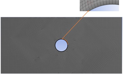
The numerical computation of drag and lift coefficient for different Reynold’s number is studied using Ansys Fluent 19.1. The 2-D cylinder of diameter 5 mm is formed and computational domain is created around it having dimensions of 150 mm×70 mm. The fluid domain with boundary conditions is given in Fig. 1. The inlet is assigned as velocity inlet and outlet is having atmospheric pressure i.e. 101325 Pa and all other walls are having no slip condition. The structured 2-D quadrilateral mesh is used for the domain and inflation layers are formed around the cylinder. The mesh with inflation layers is shown in Fig. 2.
The steady pressure-based solver is used to study the aerodynamic effects around the cylinder. The turbulence model used is standard k-ε and SIMPLE scheme is used for pressure and velocity coupling with second order upwind for momentum.
Fig. 1Domain around the cylinder
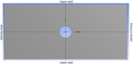
Fig. 2Meshing around the cylinder with inflation layers
4. Results and discussion
The numerical simulation around cylinder is carried out by varying the velocity at inlet to get different Reynold’s number and to analyze the change in lift, drag and pressure coefficient with respect to Re. Table 1 shows the drag coefficient and lift coefficient values for different Reynold’s number. The plot for the averaged Cd and Cl along the increasing Re is shown in Fig. 3 and Fig. 4 respectively. It is observed that the drag coefficient decreases on increasing the Re while lift coefficient increases up to Re= 104 and drops for higher Re.
Table 1Coefficient of lift and drag coefficient for different Reynold’s number
Reynold’s number | Coefficient of drag (Cd) | Coefficient of lift (Cl) | |
Re1 | 100 | 0.027670638 | 4.0792E-05 |
Re2 | 1000 | 0.017270244 | 9.78343E-05 |
Re3 | 10000 | 0.013354575 | 0.000193594 |
Re4 | 100000 | 0.008396121 | 0.000159222 |
Re5 | 1000000 | 0.006609571 | -8.03183E-05 |
Fig. 3Coeffcient of drag vs Reynold’s number
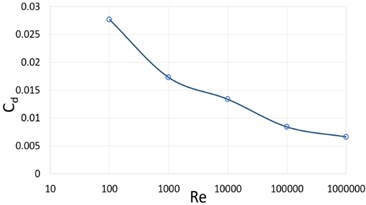
Fig. 4Coeffcient of lift vs Reynold’s number
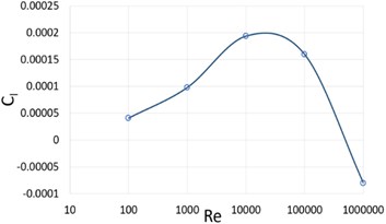
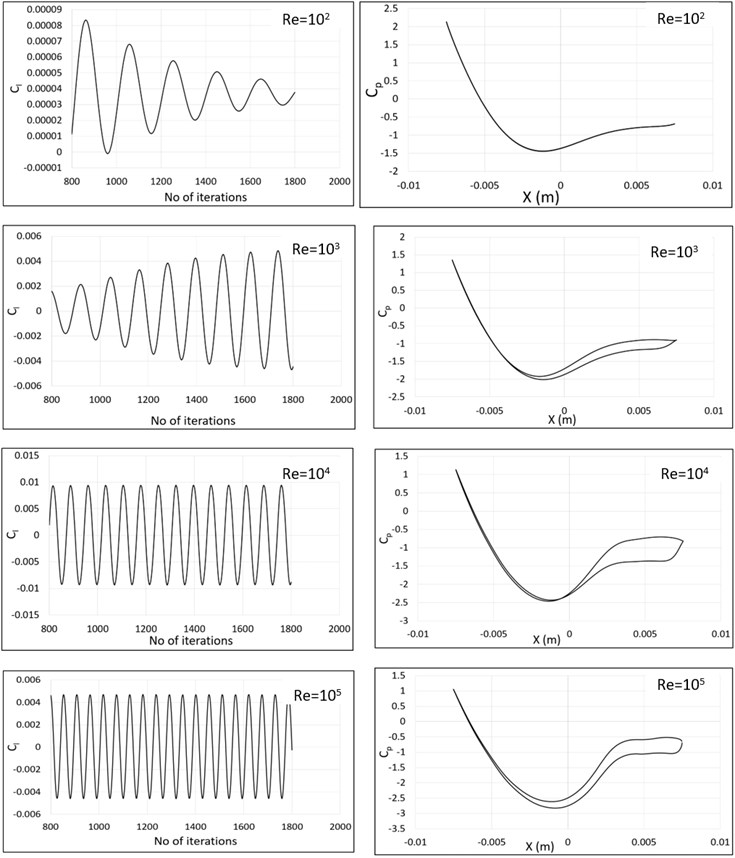
Fig. 5 represents the coefficient of lift and pressure distribution on fixed cylinder for at Re=102 ,103 ,104 and 105. The Cl is plotted for the iteration ranging from 800 to 1800. The Cl value increasing as Re increases till 104 while decreases for further higher values which can be seen from the graph. The value of pressure coefficient is having overlapped curve for at Re=102 and the difference between pressure distribution increases along the increasing Re.
Fig. 5The lift coefficient and pressure coefficient distribution along the fixed cylinder wall at different Reynold’s number
The vorticity contour is plotted in Fig. 6 to check the wake pattern on the cylinder for increasing Re. The range of vortex shedding is kept from –104 to 104. The oscillations around the cylinder increases with Reynold’s number forming von Karman street around the cylinder. It can be seen that separate shear layers are rolling on the upper and lower wall of fixed cylinder. The red color in the vorticity contour represents the clockwise rotation while blue color represents the counterclockwise rotation of vortices.
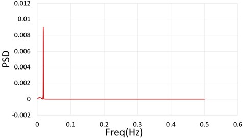
To understand the oscillations around the cylinder due to formation of vortex shedding the power spectral density of the lift coefficient is determined using Fast Fourier Transformation. The maximum frequency for the Re= 105 using FFT is 0.018 Hz. Fig. 7 represents the power spectral distribution for the same.
Fig. 6Velocity contours at different Reynolds numbers
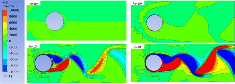
Fig. 7Power spectral distribution vs frequency
5. Conclusions
In this paper the numerical computation for the lift and drag coefficient with increasing number of Reynold’s number is represented. The drag coefficient reduces with the increasing Re and lift coefficient increases up to Reynold’s number 104. Similarly, the pressure difference on the fixed cylinder increases with the increasing Reynold’s number. The vorticity contour and power spectral distribution of lift coefficient is also presented in the results and discussion section.
References
-
Martinez R. C., Sweeney L. G., Finlay W. H. Aerodynamic forces and moment on a sphere or cylinder attached to a wall in a Blasius boundary layer. Engineering Applications of Computational Fluid Mechanics, Vol. 3, Issue 3, 2009, p. 289-295.
-
Xiong Y., Peng S., Zhang M., Yang D. Numerical study on the vortex-induced vibration of a circular cylinder in viscoelastic fluids. Journal of Non-Newtonian Fluid Mechanics, Vol. 272, 2019, p. 104170.
-
Singha S., Sinhamahapatra K. Flow past a circular cylinder between parallel walls at low Reynolds numbers. Ocean Engineering, Vol. 37, Issues 8-9, 2010, p. 757-769.
-
Rajani B. N., Kandasamy A., Majumdar S. Numerical simulation of laminar flow past a circular cylinder. Applied Mathematical Modelling, Vol. 33, Issue 3, 2009, p. 1228-1247.
-
Chopra G., Mittal S. Numerical simulations of flow past a circular cylinder. Journal of Physics: Conference Series, Vol. 822, 2017, p. 012019.
-
Brika D., Laneville A. Vortex-induced vibrations of a long flexible circular cylinder. Journal of Fluid Mechanics, Vol. 250, 1993, p. 1-481.
-
Shim Y. M., Sharma R., Richards P. Numerical study of the flow over a circular cylinder in the near wake at Reynolds number 3900. 39th AIAA Fluid Dynamics Conference, 2009.

