Abstract
Wake-induced vibrations of a 2-DOF circular cylinder which is placed behind a stationary square cylinder with tandem arrangement are numerically investigated at low Reynolds numbers by using semi-implicit Characteristics-based split (CBS) finite element algorithm in this study. Numerical results demonstrate that the side length of the upstream square cylinder can significantly affect the characteristics of flow patterns, oscillation frequency, maximum amplitudes, X-Y trajectories, and hydrodynamic coefficients of the rear circular cylinder. The predominant vortex shedding patterns are 2S, 2P and 2T mode. In addition to the figure “8”, “raindrop” and figure “dual-8” are observed in the X-Y vibrating trajectories for the circular cylinder. Finally, the interactions between cylinders are revealed according to the phase portrait of fluid force to displacement and the power spectral densities (PSD) features of the vibration amplitude on the rear circular cylinder and the instantaneous flow field, together with the wake-induced vibration (WIV) mechanism underlying the oscillation characteristics of the circular cylinder behind a stationary square cylinder with different sizes.
1. Introduction
Vortex-induced vibration (VIV) is a practical subject with potential significances in many engineering fields, such as bridges and chimney stacks, heat exchanger tubes, marine vehicles, and ocean risers. VIV of an elastically mounted circular cylinder, as one of the most fundamental problems for this subject, has been extensively studied. When the cylinder is vibrating only in the transverse direction, flow patterns, such as ‘2P’, ‘2S’, and ‘P+S’ (where S means a single vortex and P means a pair of vortices), can be observed at different parameter configurations. They are always coupled with the three typical branches, e.g. the initial, upper and lower branches, with the lock-in characteristic in the upper branch in which the cylinder’s non-dimensional vibrating amplitude can reach up to 1.0. As the cylinder can oscillate in inline and transverse directions, the cylinder’s motion always shows shapes of figure-8 and O. Meanwhile, its non-dimensional vibrating amplitude can be as higher as 1.5 together with a ‘2T’ wake pattern (T means a triple of vortices). For more details of the VIVs of one circular cylinder, the review literatures by Williamson and Govardhan [1], Sarpkaya [2], Gabbai and Benaroya [3], Bearman [4] and Wu et al. [5] can be referenced.
When two or more flexible cylinders immersed in the fluid domain are arranged in staggered or tandem configuration, a sub-branch of VIV, termed wake-induced vibration (WIV), arises. Different from the case of a single cylinder which is caused to vibrate by the vortices shedding from the cylinder itself, the downstream cylinder’s oscillations in WIV are also strongly affected by the incoming vortices generated from the upstream one. Although in recent years the research on WIV has attracted greater attention [6-14], understanding on this issue is still not as adequate as the single cylinder case yet.
Assi et al. [6-8] performed experimental investigations in still water on wake-induced vibration interferences between two tandem circular cylinders with 1-DOF and 2-DOF at different spacing ratios in the high Reynolds number region, respectively. They observed interference galloping patterns for a gap spacing ratio ranging from 2 to 5.6. There have been a lot of studies implementing numerical methods to investigate the WIV effect. Borazjani and Sotropoulos [9] reported the flow characteristics of two tandem VIV cylinders having both one and two degrees of freedom at a small spacing ratio L/D=1.5, and concluded that the initial excitation mechanisms were dominated by the vortex-shedding pattern at low reduced velocities, but as it became higher, the gap-flow mechanism would provide the power for the shedding vortices. This kind of wake flow can be categorized as proximity-wake interference. Carmo et al. [10] numerically investigated 2D and 3D of the wake-induced vibration of a circular cylinder which only oscillates in the transverse direction behind the fixed cylinder at different spacing ratios (L/D= 1.5-8.0), respectively. They pointed out that the variation of spacing ratio has a significant influence on the dynamic behavior of the rear cylinder. Lin et al. [13] studied the effects of some key parameters, such as spacing ratio, reduced mass and reduced velocity, on the transversely vibrating cylinders in tandem arrangement by lattice Boltzmann method. The biased vibration region was found in the cases of large reduced velocity, small separation and low reduced mass at subcritical Re. Mittal and his collaborators conducted numerical simulations for two identical circular cylinders with spacing ratio of 5.5 [15, 16]. The downstream cylinder showed a higher amplitude in the transverse direction, which was regarded as a typical characteristic of the WIV. Papaioannou et al. [17] investigated the influences of gap spacing and reduced velocity on the vortex-induced vibration of two tandem cylinders with Re=160, Mr= 10 and damping coefficient ξ= 0.01 using numerical method. Three cases of spacing ratios (L/D= 2.5, 3.5, 5.0) were reported, respectively. Compared with an isolated cylinder case, the dynamic motions of the bodies and flow field were more complex. Bao et al. [18] conducted a numerical investigation on the vortex-induced vibration of two oscillating cylinders in the tandem arrangement with different natural frequencies at L/D= 5.0. They pointed out that the dynamic characteristic of the upstream cylinder was similar to that of a single cylinder, whereas that of the downstream cylinder was greatly affected by the upstream wake. In addition, the in-line dynamic response was more sensitive to the natural frequency ratio than the response in the transverse direction.
Recently, Selvakumar and Kumaraswamid [19] reported that an experimental investigation was performed in a low-speed wind tunnel in which an elastically mounted circular cylinder was surrounded by from one to six identical cylinders and the fluid flow characteristics; and the possibility of suppressing flow-induced vibration excitation in the test cylinder were predicted. Wang et al. [20] performed numerical studies of WIV of two unequal-sized circular cylinders in tandem arrangement with the spacing ratio of 5.5. The oscillation amplitudes and trajectory figures of the downstream cylinder were analyzed. In our previous work [12, 21], WIV of a circular cylinder behind a stationary circular/square cylinder with equal size was investigated, in term of dynamic response, wake pattern distributions and the fluid-solid interaction dynamics.
The aforementioned studies used experimental techniques and numerical simulation methods. The advantages of experiment lie in that the Reynolds number is as high as in the turbulence flow, which can simulate the real engineering situation, but the experiment would be limited by some specified parameters. In contrast, the numerical simulation method is able to comprehensive analyze the vibrations under various conditions by changing a variety of parameters, such as Reynolds number, spacing ratio and reduced velocity. In addition, typical characteristics of the VIV at large Reynolds number obtained in the experiments can also be revealed by numerical simulations [22]. However, one drawback of numerical simulation method is that the computational cost would be significantly increased, as the Reynolds number becomes greater [23]. Although the previous studies can provide preliminary understandings, due to the complicated nature of WIV, the mechanisms and characteristics of WIV have not been well addressed for cylinders in tandem arrangement with different side lengths and spacing ratios.
In the current study, we continue to investigate the WIV of the two-cylinder system using a numerical simulation method. This system is comprised of an unequal-sized upstream stationary square cylinder and a two-degree-of-freedom (2-DOF) downstream circular cylinder. In this work, the side length of the square cylinder is changed from 0.2 to 2.0 times of the diameter of the circular cylinder, while the spacing ratio is set as higher as 10 which is expected to provide an enough gap for the fully developed vortices between the two cylinders. The Reynolds number of the fluid-solid system is set as Re= 120 that enables two dimensional simulations for all the cases. The objectives of this study are to explore the effects of basic parameters, such as the size of the upstream cylinder and reduced velocity, on the characteristics of VIV dynamic responses, and to contribute to revealing the mechanism of wake-induced vibration for two cylinders’ tandem system in a laminar flow region.
The framework of this study is presented as follows. The details of the Arbitrary Lagrangian-Eulerian (ALE) forms of the fluid governing equations, the solid movement equations are described firstly. To validate the computational code, the study of coupled cross-flow/in-line VIV of the single circular cylinder is carried out, with the simulated results in accordance with existing data. Then, we elaborate on the flow characteristics and dynamic behaviors of the rear circular cylinder as well as the wake-induced vibration mechanism underlying the dynamic responses of the cylinder are elucidated. Finally, some main conclusions of this work are summarized in the last section.
2. Numerical method and code verification
2.1. Governing equations and numerical details
To account for the fluid dynamics in the VIV and WIV systems, the non-dimensional Navier-Stokes (N-S) equation and the continuity equation for the incompressible viscous flow are employed, shown in Eqs. (1-2). Both equations are described under the ALE framework [24]:
where ui represents the fluid velocity, and wi the grid velocity tensor in the ith direction, p the pressure, xi (i= 1, 2 in 2-D problem and 1, 2, 3 in 3-D problem) the Cartesian coordinates, and t the time. Further, the Reynolds number is Re=(U∞D)/v, where D= 1.0 is the characteristic length in the non-dimensional fluid domain, U∞ the free stream velocity, and v the fluid kinematic viscosity.
The computation procedure forms into a semi-implicit CBS scheme, which is expected to be more stable and robust than the classical explicit one [21, 26, 27]. Details of the CBS algorithm have been shown in our previous publication [21]. Some essential equations of the algorithm are listed as below:
=-(unj-wnj)∂uni∂xj+12Re∂2uni∂xj∂xj,
The movement governing equations of the oscillating cylinder with two-degrees-of-freedom (2-DOF) are modeled as a mass-spring damper system. The solid dynamic Eqs. (6-7) can be solved by a Newmark-β type method introduced in the work by Bao et al. [12]. The discrete forms of the computational steps are also presented in Han et al. [21]:
where, the X and Y are the cylinder displacements in the x1- and x2- direction. Mr=4m/(πρD2) is the cylinder’s non-dimensional reduced mass, where m is the cylinder mass of a unit length, and ρ is the fluid density. ξ is the structural damping ratio. Ur=U∞/(fnD) represents the reduced velocity, where fnis the natural frequency of the cylinder. CL=(2FL)/(ρU2∞D) and CD=(2FD)/(ρU2∞D) are the lift and drag coefficients, as FL and FD are lift and drag force applied on the cylinder, respectively.
The cylinder motion within a time step will induce the updating of the grid. The grid displacement, Wi, is calculated using a Laplace-related algorithm shown as follows:
where γ is a parameter for controlling the mesh deformation. The grid velocity is calculated by wi=(∂Wi)/∂t. Eq. (8) can be solved by standard FEM procedure. Details of the grid updating scheme is introduced in Wang et al. [20].
For solving the VIV case which is one of the typical fluid-structure interaction (FSI) problems, the staggered algorithm is employed. This scheme has been used for satisfactory solutions as shown in the publications [12, 20, 28]. Briefly, the computational steps during one time interval ∆ are summarized as: (a) obtain the velocities and pressure in the fluid domain by the CBS algorithm; (b) calculate the drag and lift coefficients, and , of the cylinder, and compute the cylinder motions, and , by the Newmark- type method; (c) get the updated grid movements, , using the equation; (d) return to step (a) to restart a new iteration step until the VIV behaviors become stable.
2.2. Code verification
The computational code has been verified in our previous work [21, 29]. We further validate the accuracy of the computational approach by using it to solve the VIV of an isolated cylinder with two degrees of freedom in uniform cross-flow. This example has also been taken as a reference by Papaioannou et al. [17]. The free oscillation of a circular cylinder with 2-DOF is carried out in the subsection. The size of flow domain, the geometry of the model and boundary conditions are given in Fig. 1(a). The cylinder whose center locates at point (0, 0) has a diameter 1.0. The entire computational domain is defined as [–25, 54]×[–30, 30]. On the surface of the cylinder it is imposed as , and a uniform flow used at the inlet of the computational domain as a boundary condition is prescribed to be 1.0 and 0.0, while the pressure is set to zero at the outlet. Symmetry conditions are used at the lateral boundaries as: 0.0, 0.0. The system parameters are set as follows: the reduced mass 10.0, the damping ratio 0.01, the reduced velocity 3.510.0, the damping ratio Reynolds number 160 and 0.002.
The schematic mesh grids for the whole computational domain and around the cylinder are respectively illustrated in Figs. 1(b) and 1(c). In the wake flow region and the area around the cylinder, higher resolutions of grid density are acquired. To test the mesh independency, a mesh-refinement study is performed. Three groups of grid system are adopted in the current examples. In Grid I, there are 100 nodes on the surface of the cylinder, while in Grid II and Grid III there are 200 and 400 nodes, respectively. Some details of the three groups are presented in Table 1, which also provide the results of some grid parameters, with the percentage changes written inside the bracket. It is observed that the maximum deviation of results, such as and , is 6.03 %, when comparing Grid I with Grid II, whereas no significant change exists between Grid II and Grid III (only 2.52 % change in the value of ). Therefore, all the investigations presented hereafter are based on the mesh characteristics of Grid II.
Fig. 1Schematic of an isolated oscillating circular cylinder
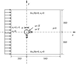
a) The computational domain and boundary conditions
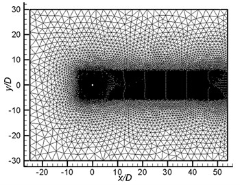
b) The whole mesh
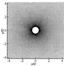
c) Meshes around the cylinder
Table 1The grid independence test for the freely oscillating circular cylinder at Ur= 4.5 and Re= 160
Grid | Grid nodes distributed on the cylinder | No. of elements | No. of nodes | ||
Grid I | 100 | 25 357 | 12 738 | 0.0109 | 0.502 |
Grid II | 200 | 50 697 | 25 429 | 0.0116 (6.03 %) | 0.525 (4.38 %) |
Grid III | 400 | 92 391 | 45 836 | 0.0119 (2.52 %) | 0.533 (1.50 %) |
Comparisons in the non-dimensional maximum amplitudes () in 2-DOF are shown in Fig. 2 between our results and existing data [17]. As shown in Fig. 2, these results are in good accordance with each other, verifying that the numerical scheme and resolution used in this paper are adequately accuracy and reliable for the solution of VIV in the laminar region.
Fig. 2Comparisons on the dimensionless maximum vibration amplitudes from present numerical results with existing data (Papaioannou et al., [17]) for a 2-DOF oscillating circular cylinder
![Comparisons on the dimensionless maximum vibration amplitudes from present numerical results with existing data (Papaioannou et al., [17]) for a 2-DOF oscillating circular cylinder](https://static-01.extrica.com/articles/17611/17611-img4.jpg)
a) Inline direction ()
![Comparisons on the dimensionless maximum vibration amplitudes from present numerical results with existing data (Papaioannou et al., [17]) for a 2-DOF oscillating circular cylinder](https://static-01.extrica.com/articles/17611/17611-img5.jpg)
b) Transverse direction ()
3. Problem description
The computational model is illustrated in Fig. 3. Two cylinders are positioned in the fluid domain with an inline configuration. The upstream cylinder is a square shape with the side length of , and the diameter of the downstream circular cylinder is 1.0, which is also equal to the characteristic length in the fluid domain. The fluid domain is configured as [–35, 65×] [–30, 30], and the centers of the two cylinders are placed at (–10, 0) and (0, 0), so that the spacing ratio is 10. The square cylinder is kept stationary, while the circular cylinder is capable of freely oscillating with a two-degree-of-freedom (2-DOF) characteristic by connecting with a spring-damping system in the inline and transverse directions, respectively. The natural frequencies of the circular cylinder in the two directions are set identical as . The reduced mass of the circular cylinder is as low as 2.546. The damping coefficient of the dynamic system is 0.0 in order to enable its highest amplitude. During the computations, the reduced velocity, , is changed from 3 to 26. The Reynolds number is fixed as 120, which is in the laminar flow regime and enables the 2D computations. To test the effects of ratio on the WIV system, the side length of the square cylinder varies, with the value set as 0.2, 0.5, 1.0, 1.5, and 2.0, respectively. The dimensionless time step is 0.002. The computation stops when the FSI system is fully development to a stable state.
Most of the boundary conditions are exactly the same as those in the 2-DOF VIV circular cylinder benchmark case in the previous section. The only difference is that on the surface of the square cylinder, 0 and 0; on the surface of the 2-DOF circular cylinder, and .
4. Flow characteristics and dynamic responses of the rear circular cylinder
4.1. Flow patterns
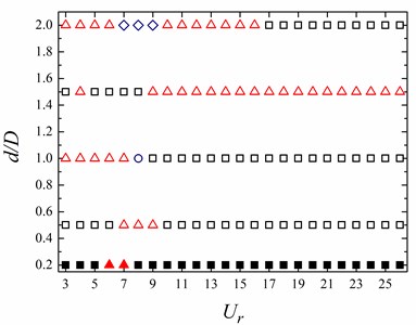
Fig. 4 summarizes the wake patterns to show how they are affected by the and . Three types of fully developed flow pattern, 2S, 2P and 2T, are observed at different side length ratios () and reduced velocities (). At lower , the 2S and 2P mode are dominant. The vortex street is not formed in the gap between both cylinders at 0.2, as seen in Figs. 5(a) and (b). With the increasing of , vortex shedding phenomenon is clearly seen behind the square cylinder, as seen in Figs. 5(c)-(e). At 1.0, 2 and 2 modes are observed at 3 7 and 9 26, respectively. 2T mode occurs at 1.0 and 8, as seen in Figs. 5(d). On the contrary, as 1.5, 2P mode occurs at higher (9 26) and 2S mode shows at lower . At 2.0, the predominant vortex shedding patterns are 2S and 2P mode. It is worth noting that a pair of vortices sheds from both upper and lower sides of the rear cylinder, as seen in Fig. 5(e), and the shape of vorticity behind the rear circular cylinder resembles the figure-eight, then two vortices gradually merge into a big one.
Fig. 3Computational model and boundary conditions for the oscillating circular cylinder behind a stationary square cylinder
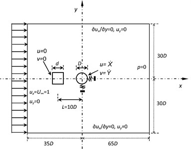
Fig. 4Flow pattern distributions at different side length ratios (d/D) and reduced velocities (Ur) for the WIV of the circular cylinder: ∆ = 2S pattern (solid and open squares denote steady and wake in the gap between cylinders, respectively.); ◇= 2S pattern with the figure-eight shape of vorticity; ∆ = 2P pattern (solid and open triangles denote steady and wake in the gap between cylinders, respectively.); and ○ = 2T pattern
4.2. Frequency of oscillation
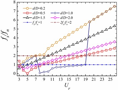
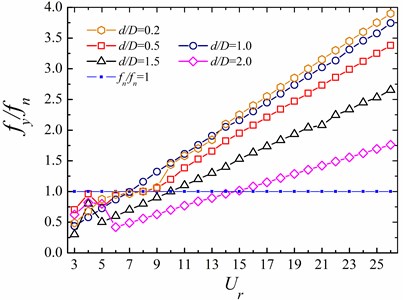
Fig. 6 shows the relationships between frequency ratios (, ) and reduced velocities related to the WIV systems. The definitions of these frequencies are given as follows: , the natural frequency of the circular cylinder; and : the main vibrating frequency of the circular cylinder in the - and - direction, respectively.
As shown in Fig. 6(a), when the reduced velocity is small (3 9), the variations of frequency ratio as a function of reduced velocity are obvious with the increasing of size ratio in the inline direction. At 0.2, the gradually increases as increases. The inline vibrating frequency, , is twice of its natural frequency, 2, for 5 9. For the case of 0.5, the gradually decreases with the increasing of and reaches the minimum value at 5, and then it increases. While, the trend of at 1.0 with the change of is reverse to that of the 0.5 case: it reaches a peak as high as 2.0 at 7, and then followed by a dramatic decrease at 8. As the size ratio further increases, the value of continuously increases with the increasing of . Additionally, for the large reduced velocity (9 26), the trend of with the change of is the same at different size ratio cases: with the increasing of , the value of gradually increases. It should be noted that, for the case of 1.0, the value of is smaller than that of the other cases in the range of 9 19, and the frequency ratio is close to 1.0 for 14 19.
Fig. 5Instantaneous vorticity contours for the WIV system at different cases

a) 0.2, 4

b) 0.2, 7

c) 0.5, 8

d) 1.0, 8

f) 1.5, 10

e) 2.0, 8
Fig. 6The relationships between frequency ratio and reduced velocity for the rear circular cylinder at different ratios of d/D
a) In the -direction ()
b) In the -direction ()
On the other hand, with the change of , there is a change trend of vibration frequency only with small variations at small reduced velocities in the transverse direction. It can be found from Fig. 6(b), the change of has a great influence on the resonance region of downstream cylinder. For the small , the transverse vibration frequency is close to the natural frequency in the range of 5 9. However, for the large , the synchronization phenomenon occurs at 6 8 ( 1.0), 9 11 ( 1.5), 14 16 ( 2.0), respectively.
4.3. Amplitude of oscillation
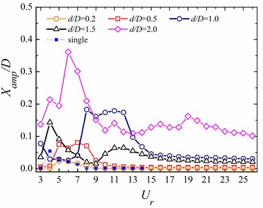
To understand the effects of the shape and reduced velocity changes on the dynamic responses of the downstream circular cylinder, the relationships of non-dimensional maximum vibrating amplitudes for the circular cylinder under various reduced velocities in different cases are presented in Fig. 7. Additionally, the results of the single cylinder case with similar structural parameters are also plotted for comparison. The is the maximum vibrating amplitude defined as ( within one vibrating cycle, while is that of (.
Fig. 7The relationships between the maximum vibrating amplitude and reduced velocity for the circular cylinder at different ratios of d/D
a) In the -direction ()
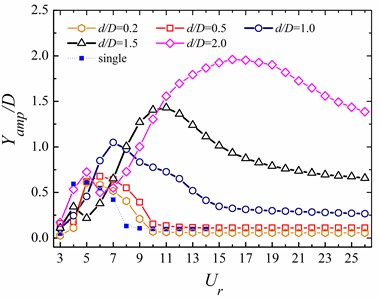
b) In the -direction ()
It can be observed from Fig. 7 that the maximum amplitudes of the rear cylinder are very close to those expected for an isolated cylinder at almost the same reduced velocity for the lower . There is no vortex street behind the square cylinder, as seen in Figs. 5(a) and 5(b). Hence, the wake of the square cylinder has a significant effect on the rear one. The same behavior was also observed in the published literatures [14, 17]. With the increasing of , the changes of oscillation amplitude at both the inline and transverse direction are obvious. In the inline direction, the vibration amplitude of circular cylinder is very small at lower reduced velocities. The value of gradually increases until it reaches a peak at 5 ( 0.5) and 8 ( 1.0), respectively. Then the values of keep larger in the range of 5 8 ( 0.5) and 8 12 ( 1.0). The oscillation amplitude in the inline direction gradually decreases and then it remains constant in the higher reduced velocity region. On the other hand, as 0.5, the maximum amplitude () firstly increases until it reaches the maximum at 6, and then decreases, and finally maintains a smaller value at the higher reduced velocities (). The trend of transverse vibration amplitude at 1.0 is similar to that of 0.5 case. It should be noted that there is a dramatic increase in the peak value of for every case. It reaches a peak as high as 0.67 at 6 and 0.5, while as 1.0 the peak value of reaches 1.05 at 7. For the higher , the dynamic characteristics of the circular cylinder only appears the ‘single-resonance’ phenomenon in the transverse direction for 1.5, while the performance of ‘dual-resonance’ is found at 2.0. For 1.5, the oscillation amplitude in the inline direction is smaller in comparison with the case of 2.0. However, the trend of is similar to that at 2.0: as continuously increases, the value of increases until it reaches a local peak at 4, then gradually decreases to be a small value, increases again, and finally approaches to a constant. In addition, the peak of the transverse amplitude occurs at 11 ( 1.5), and 16 ( 2.0), respectively. It should also be noted that a dramatic change in the can be found at 2.0. The comparisons between the current case and the other cases additionally demonstrate that parameters, such as spacing ratio, cylinder shape, and the existence of the front cylinder, have a significant influence on the vibrations of the rear circular cylinder.
4.4. - trajectories of the rear circular cylinder
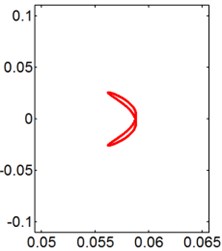
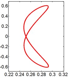
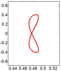
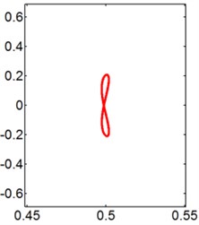
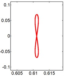
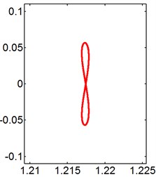
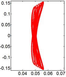
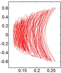
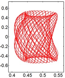
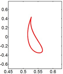
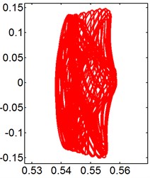
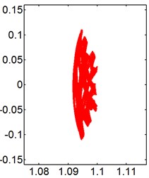
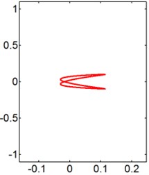
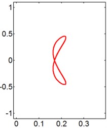
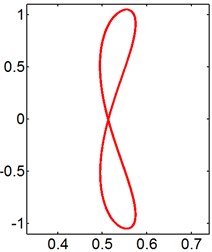
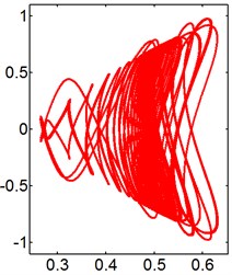
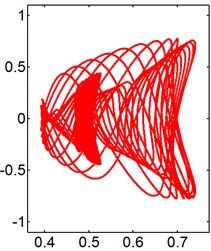
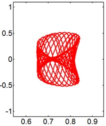
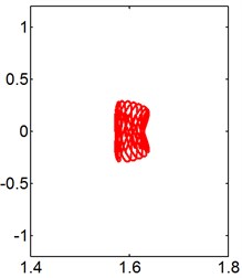
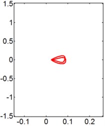
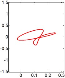
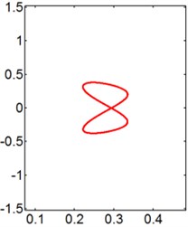
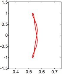
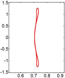
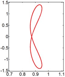
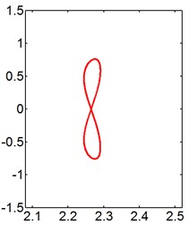
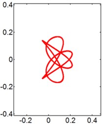
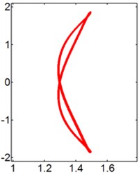
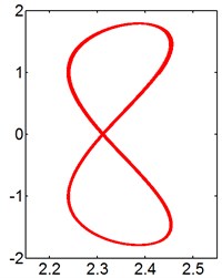
In general, the trajectory of an isolated elastically mounted cylinder resembles a figure “8”, while the motion shows the shapes of figure “8”, figure “dual-8” and raindrop for the cylinder behind a stationary square cylinder. The Lissajous figures of the trajectory for two tandem cylinders at different reduced velocities when 0.2, 0.5, 1.0, 1.5 and 2.0 are presented in Figs. 8-12, respectively.
For the smaller ( 0.2), the dynamic behaviors are similar to those expected for an isolated cylinder, and the motion orbits of the circular cylinder resemble figure “8” motion, as seen in Fig. 8. It can be seen that, the downstream circular cylinder motions appear to be figure “8” type and its amplitude is quite low in the unlock-in region. However, in the range of lock-in, the oscillation amplitude is large in the transverse direction. It represents the result associated to the ‘single-resonant’ only in the transverse direction.
Fig. 8X-Y trajectories of the 2-DOF circular cylinders behind a square cylinder under different reduced velocities at d/D= 0.2
a) 3
b) 5
c) 8
d) 9
e) 10
f) 12
As increases up to 0.5 and 1.0, the change of has a significant influence on the motion of the downstream cylinder. The Lissajous figures of the trajectory resemble irregular figure at 0.5, as shown in Fig. 9. The dominant of cylinder orbital trajectories is irregular figure 8 for the small , while the motion orbit transforms from the raindrop to a messy and unrepeatable trajectory at 9. Additionally, at 1.0, with the increasing of , the shape of cylinder motion transforms from the figure “8” to the irregular shape.
For the larger cases ( 1.5 and 2.0), the prominent - trajectories of the circular cylinder are figure “8” and figure “dual-8”, as shown in Figs. 11 and 12. As 4, the motion orbits of downstream cylinder is not symmetrical to the central line. A possible explanation for this feature is that the transverse fluid force on the surface of the cylinder is unbalanced, shown in Fig. 14(c). Additionally, the Lisasajous figure of the circular cylinder exhibits vertical figure “dual-8” at 8 and 1.5. Moreover, the motion orbit of the circular cylinder shows the lateral figure “dual-8” shape at 6 and 2.0, which is symmetrical to the central line. With the increasing of , the oscillation amplitude of the cylinder in the transverse direction gradually increases, then maintains a large value Fig. 7(b), and the shape of cylinder motion transforms from the lateral figure “dual-8” to the figure “8”. As further increases, the motion orbit of the rear cylinder exhibits vertical figure “dual-8” at 14. And then the shapes of cylinder motion show figure “8” again at larger .
Fig. 9X-Y trajectories of the 2-DOF circular cylinders behind a fixed square cylinder under different reduced velocities at d/D= 0.5
a) 3
b) 5
c) 8
d) 9
e) 10
f) 14
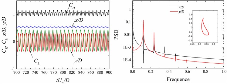
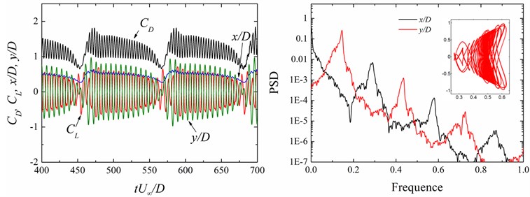
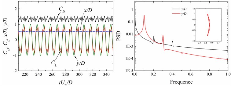
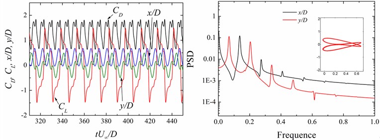
Fig. 13 shows the time histories of the motions (, ) and the fluid force coefficients (, ) of the rear circular cylinder, power spectral densities (PSD) of the displacements and the oscillation orbits at different cases. It is worth noting that in this study the motion of the cylinder is sensitive to the size of the upstream square cylinder. With the change of size ratio ( 0.2-2.0), the motion of the cylinder converts from the figure “8” trajectory to the raindrop one for the small case, and then it shows irregular figure “8”; the - trajectory resembles figure “dual-8” in the single-resonance response and the response characteristics appear dual-resonance phenomena with a further increasing value of .
To explain the effect of the size of the upstream square cylinder on the vibration characteristics of downstream cylinder, the phase portraits of the forces (, ) relative to the vibrations (, ) of the downstream cylinder are presented in Fig. 13. The size ratio has a significant effect on the phase portraits of the forces and the corresponding motions of the cylinder. In the cases of 0.5 and 9, the phase portrait of relative to is out-of-phase, giving rise to the smaller-amplitude oscillation in the in-line direction, seen in Fig. 13(a). However, for the case of 1.0 and 8, the time of each cycle for the rear cylinder is longer, acting as a modulation period. With the increasing of , the phase portraits of fluid forces relative to displacements are similar to that of the case of 0.5 and 9, seen in Fig. 13(c). As the further increases to 2.0, the phase portrait of relative to changes from out-of-phase to in-phase, resulting in the larger-amplitude oscillation in the inline direction. Hence, the size ratio of two cylinders causes the changes of the energy transferring process and the oscillation amplitude.
Fig. 10X-Y trajectories of the 2-DOF circular cylinders behind a fixed square cylinder under different reduced velocities at d/D= 1.0
a) 3
b) 5
c) 7
d) 8
e) 10
f) 13
g) 20
On the other hand, with the change of , the PSD features of the vibration displacement singles dramatically change. The above-mentioned VIV responses are explained conveniently in terms of the characteristics of PSD. The multiple vibration frequency components of the displacements at both the inline and transverse direction are co-triggered at the same frequency, resulting in the raindrop motion, as shown in Fig. 13(a). The same phenomenon was also observed in our previous work [28]. With the increasing of , the multiple vibration frequency components of the transverse direction with those of the inline one and the dominant vibration frequency in the transverse direction is twice of that in the inline one. Hence, the - trajectory shows the irregular figure “8”, as shown in Fig. 13(b).
For the larger size ratio, there are only the 1st and 2nd harmonic contents in the displacement singles at both the inline and transverse direction and the dominant vibration frequency in the transverse direction is twice of that in the inline one, seen in Fig. 13(c). However, the value of PSD relative to the dominant transverse vibration frequency is much greater than that in the inline direction. Hence, the oscillation of the circular cylinder shows signal-resonance of figure “dual-8” motion. When the values of PSD relative to the dominant vibration frequency are the same at both the transverse and inline direction in the case of 2.0 and 6, resulting in the inline vibration of the cylinder significantly intensifying and the dual-resonance of figure “dual-8” motion.
Fig. 11X-Y trajectories of the 2-DOF circular cylinders behind a fixed square cylinder under different reduced velocities at d/D= 1.5
a) 3
b) 4
c) 6
d) 8
e) 9
f) 10
g) 20
4.5. Hydrodynamic coefficients
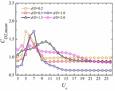
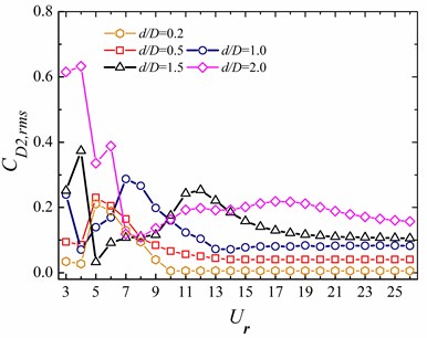
Due to the long distance between the two cylinders, the effect of the rear cylinder on the front one is insignificant and the upstream square cylinder behaviors are similar to the single cylinder case. Hence, we only select the data of the rear cylinder to display the hydrodynamic characteristics of the WIV system in the subsection. The mean and root mean square (rms) values of the hydrodynamic coefficients, including the drag and lift coefficients ( and ), of the two cylinders are shown in Fig. 14, respectively.
Fig. 12X-Y trajectories of the 2-DOF circular cylinders behind a fixed square cylinder under different reduced velocities at d/D= 2.0
a) 3
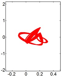
b) 4
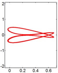
c) 6
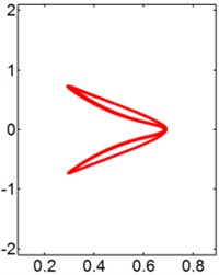
d) 8
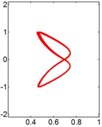
e) 9
f) 14
g) 20
The mean drag coefficient () of the vibrating downstream circular cylinders increases with the reduced velocity until it reaches the peak values, then decreases, as shown in Fig. 14(a).
The peak value for the smaller occurs at 5-7, respectively. However, it occurs at 10 for 1.5. Most of the values of are around zero Fig. 14(c), which is mainly induced by the symmetrical vibrations of the circular cylinders. It is worth noting that for 1.5 and 2.0, the - trajectories of the rear circular cylinder at 4 is not symmetrical about the central line, as shown in Figs. 11(b) and 12(b), which is responsible for the sudden “jumps” in the curves of vs . Figs. 14(b) and (d) shows that both and have a great influence on the variations of the and .
Fig. 13Time history of the force coefficients (CD, CL) and displacements (x/D, y/D) and power spectral density (PSD) functions of the displacement signals (x/D, y/D) at different cases
a)0.5, 9
b)1.0, 8
c)0.5, 8
d)2.0, 6
Fig. 14Hydrodynamic coefficients at different reduced velocities for the downstream 2-DOF circular cylinder
a) Mean drag coefficient, ()
b) Root mean square of the drag coefficient, ()
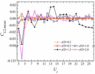
c) Mean lift coefficient, ()
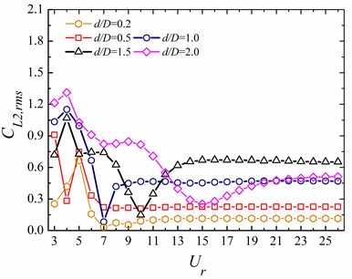
d) Root mean square of the lift coefficient, ()
4.6. Vortex dynamics of the wake-induced vibration
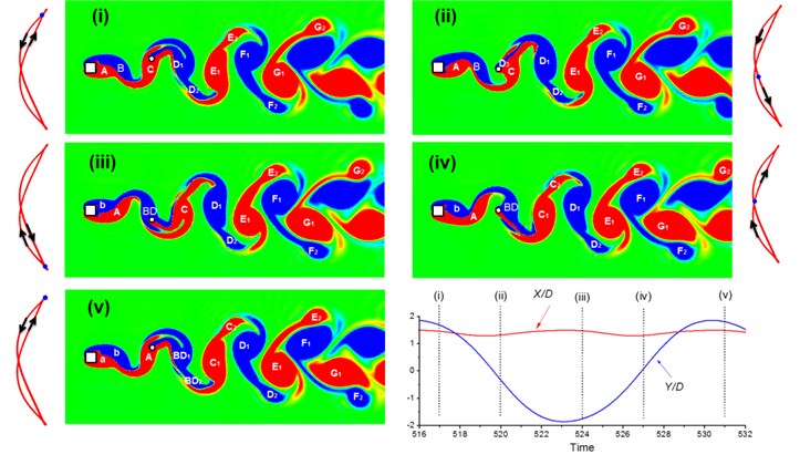
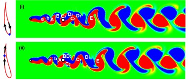
To investigate the dynamics of the WIV system, two types of the wake developments are shown in Figs. 15 and 16 by means of the instantaneous vorticity contours as well as the motions of the circular cylinder within one cycle.
Fig. 15 shows the instantaneous vorticity changes at 2.0 and 14, with stages marked from (i) to (v). The time series of the circular cylinders inline and transverse motion curves and the - trajectories which are the one type of “dual-8” are also exhibited. Also in the - trajectory figures, the position of the circular cylinder and its moving direction are marked.
As started from stage (i) where the circular cylinder is in the upper position, the vortices are marked by “----------”, which constantly move towards the downstream direction. From (i) to (ii), the circular cylinder moves downward and reaches the middle position; a new vortex “” is generated from the tail of . From (ii) to (iii), the circular cylinder keeps moving downward; “” and “” merge into a new vortex “”; a new vortex “” is generated from the square cylinder. From (iii) to (iv), the circular cylinder moves upward, and arrives at the middle position again; vortex “” develops into two vortices “” and “”; vortices “” and “” separate from each other. From (iv) to (v), the circular cylinder reaches the upper position; vortex “” develops into two vortices “” and “”; a new vortex “” appears around the square cylinder. By comparing the starting stage (i), and the ending stage (v), it can be easily identified how the vortices are developing within one period and they correspond to: from “----------”to “----------”.
Fig. 15Instantaneous vorticity developments for the WIV system at Re= 120, d/D= 2.0 and Ur= 14
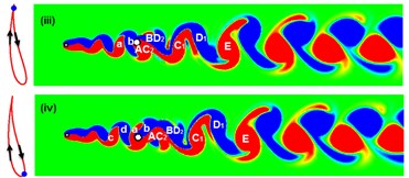
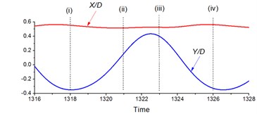
In Fig. 16 the flow pattern developments at 120, 0.5 and 9 are also investigated. At stage (i), the vortices are named as “--------” while the circular cylinder is in the lower position. From stages (i) to (ii), as the circular cylinder moves upward, vortices “” and “” merge into a new vortex “”. In (iii), the circular cylinder is in the upper position, the vortices “” and “” merge into a new “”. From (iii) to (iv), the circular cylinder moves to the lower position again, and two new vortices “” and “” are marked. Therefore, the vortices relationship between (i) and (v) is: “--------” in (i) and “-------” in (iv).
Fig. 16Instantaneous vorticity developments for the WIV system at Re= 120, d/D= 0.5 and Ur= 9
5. Conclusions
Flow characteristics and dynamic responses of a 2-DOF circular cylinder positioned behind a stationary square cylinder are investigated by using a CBS algorithm through finite element analysis. The spacing ratio is as higher as 10. The ratio of the side length of the square cylinder and the circular diameter, , varies from 0.2 to 2.0 to study its effects on the FSI system. The Reynolds number is set as 120. The flow patterns, oscillation frequency characteristics, dynamic behaviors and hydrodynamic coefficients of the rear cylinder are investigated. Key findings and conclusions are summarized as follows:
1) The vortex shedding patterns of 2S, 2P and 2T, are observed. Specially, at higher spacing ratio 10, there would be no vortices generation between the gap of the two cylinders under 120 and 0.2. Therefore, the 2S wake mode can be caused by two types: free shear layer induced vibration and wake vortex induced vibration, which is determined not only by the Reynolds number and spacing between the cylinders but also by the size ratio.
2) With the increasing of , the lock-in boundaries become wider. The transverse vibrating amplitude of the circular cylinder reaches the peak at 6 ( 0.5). However, for 2.0, the peak occurs at 16. Additionally, the dual-resonance pheromone can be found at larger size ratios.
3) The motion orbits of figure “8” and raindrop are commonly found in the - vibrating trajectories for the circular cylinder. It is worth noting that the motion orbit shows “dual-8” shape at higher such as 1.5 and 2.0 in the current case.
4) The wake-induced vibration mechanism underlying the dynamic responses of the rear cylinder is revealed according to the phase portrait of fluid forces to displacements, the PSD features of the vibration amplitudes and the instantaneous flow fields. The change of flow characteristics impacts the dynamic responses of the downstream cylinder.
It is expected that the findings and comparisons of the present work are supportive in revealing the basic mechanisms of WIV of a two-cylinder system with different cylinder size and shape, which may always occur in related engineering field such as in ocean engineering and fluid research.
References
-
Williamson C., Govardhan R. Vortex-induced vibrations. Annual Review of Fluid Mechanics, Vol. 36, 2004, p. 413-455.
-
Sarpkaya T. A critical review of the intrinsic nature of vortex-induced vibrations. Journal of Fluids and Structures, Vol. 19, 2004, p. 389-447.
-
Gabbai R., Benaroya H. An overview of modeling and experiments of vortex-induced vibration of circular cylinders. Journal of Sound and Vibration, Vol. 282, 2005, p. 575-616.
-
Bearman P. Circular cylinder wakes and vortex-induced vibrations. Journal of Fluids and Structures, Vol. 27, 2011, p. 648-658.
-
WuX. D., GeF., HongY. S. A review of recent studies on vortex-induced vibrations of long slender cylinders. Journal of Fluids and Structures, Vol. 28, 2012, p. 292-308.
-
Assi G., Meneghini J., Aranha J., et al. Experimental investigation of flow-induced vibration interference between two circular cylinders. Journal of Fluids and Structures, Vol. 22, 2006, p. 819-827.
-
Assi G., Bearman P., Meneghini J. On the wake-induced vibration of tandem circular cylinders: the vortex interaction excitation mechanism. Journal of Fluid Mechanics, Vol. 661, 2010, p. 365-401.
-
Assi G., Bearman P., Carmo B.,et al. The role of wake stiffness on the wake-induced vibration of the downstream cylinder of a tandem pair. Journal of Fluid Mechanics, Vol. 718, 2013, p. 210-245.
-
Borazjani I., Sotiropoulos F. Vortex-induced vibrations of two cylinders in tandem arrangement in the proximity-wake interference region. Journal of Fluid Mechanics, Vol. 621, 2009, p. 321-364.
-
Carmo B., Sherwin S., Bearman P., et al. Flow-induced vibration of a circular cylinder subjected to wake interference at low Reynolds number. Journal of Fluids and Structures, Vol. 27, 2011, p. 503-522.
-
Huera-Huarte F., Bearman P. Vortex and wake-induced vibrations of a tandem arrangement of two flexible circular cylinders with near wake interference. Journal of Fluids and Structures, Vol. 27, 2011, p. 193-211.
-
Bao Y., Zhou D., Tu J. H. Flow interference between a stationary cylinder and an elastically mounted cylinder arranged in proximity. Journal of Fluids and Structures, Vol. 27, 2011, p. 1425-1446.
-
Lin J. Z., Jiang R. J., Ku X. K. Numerical prediction of an anomalous biased oscillation regime in vortex-induced vibrations of two tandem cylinders. Physics of Fluids, Vol. 26, 2014, p. 132-143.
-
Tu J. H., Zhou D., Bao Y., et al. Flow-induced vibrations of two circular cylinders in tandem with shear flow at low Reynolds number. Journal of Fluids and Structures, Vol. 59, 2015, p. 224-251.
-
Mittal S., Kumar V. Flow-induced oscillations of two cylinders in tandem and staggered arrangements. Journal of Fluids and Structures, Vol. 15, 2001, p. 717-736.
-
Prasanth T., Mittal S. Flow-induced oscillation of two circular cylinders in tandem arrangement at low Re. Journal of Fluids and Structures, Vol. 25, 2009, p. 1029-1048.
-
Papaioannou G., Yue D., Triantafyllou M., et al. On the effect of spacing on the vortex-induced vibrations of two tandem cylinders. Journal of Fluids and Structures, Vol. 24, 2008, p. 833-854.
-
Bao Y., Huang C., Zhou D., et al. Two-degree-of-freedom flow-induced vibrations on isolated and tandem cylinders with varying natural frequency ratios. Journal of Fluids and Structures, Vol. 35, 2012, p. 50-75.
-
Karthik Selva Kumar K., Kumaraswamidhas L. A. Experimental investigation on flow-induced vibration excitation in an elastically mounted circular cylinder in cylinder arrays. Fluid Dynamics Research, Vol. 47, 2015, 015508.
-
Wang H., Yang W., Nguyen K. D., et al. Wake-induced vibrations of an elastically mounted cylinder located downstream of a stationary larger cylinder at low Reynolds numbers. Journal of Fluids and Structures, Vol. 50, 2014, p. 479-496.
-
Han Z. L., Zhou D., Tu J. H. Wake-induced vibrations of a circular cylinder behind a stationary square cylinder using a semi-implicit characteristic-based split scheme. Journal of Engineering Mechanics (ASCE), Vol. 140, 2014, p. 1759-1774.
-
Ding L., Bernitsas M. M., Kim E. S. 2-D URANS vs. experiments of flow induced motions of two circular cylinders in tandem with passive turbulence control for 30,000<Re<105,000. Ocean Engineering, Vol. 72, 2013, p. 429-440.
-
Zhao M., Cheng L., An H., et al. Three-dimensional numerical simulation of vortex-induced vibration of an elastically mounted rigid circular cylinder in steady current. Journal of Fluids and Structures, Vol. 50, 2014, p. 292-311.
-
Donea J., Giuliani S., Halleux J. An arbitrary Lagrangian-Eulerian finite element method for transient dynamic fluid-structure interactions. Computer Methods in Applied Mechanics and Engineering, Vol. 33, 1982, p. 689-723.
-
Zienkiewicz O. C., Codina R. A general algorithm for compressible and incompressible flow-Part I. the split characteristic-based scheme. International Journal for Numerical Methods in Fluids, Vol. 20, 1995, p. 869-885.
-
Han Z. L., Zhou D., Tu J. H. Laminar flow patterns around three side-by-side arranged circular cylinders using semi-implicit three-step Taylor-characteristic-based-split (3-TCBS) algorithm. Engineering Applications of Computational Fluid Mechanics, Vol. 7, 2013, p. 1-12.
-
Han Z. L., Zhou D., Tu J. H., et al. Flow over two side-by-side square cylinders by CBS finite element scheme of Spalart-Allmaras model. Ocean Engineering, Vol. 87, 2014, p. 40-49.
-
Tu J. H., Zhou D., Bao Y., et al. Flow-induced vibration on a circular cylinder in planar shear flow. Computers and Fluids, Vol. 105, 2014, p. 138-154.
-
Han Z. L., Zhou D., He T., et al. Flow-induced vibrations of four circular cylinders with square arrangement at low Reynolds numbers. Ocean Engineering, Vol. 96, 2015, p. 21-33.
Cited by
About this article
Support from the Key Program of National Natural Science Foundation of China (No. 51434002), the Major Program of the National Natural Science Foundation of China (No. 51490674), National Natural Science Foundation of China (Nos. 11602214, 51278297, 51679139), Hunan Provincial Natural Science Foundation of China (No. 2016JJ3117), Doctoral Disciplinary Special Research Project of Chinese Ministry of Education (No. 20130073110096), Scientific Research Project of Department of Education of Hunan Province (No. 15C1318) and China Ocean Mineral Resources Research and Development Association Project under contract No. DY125-14-T-03 are greatly acknowledged.

