Abstract
The present work is focused upon development of multi-body dynamic (MBD) models of a military tracked recovery and towed vehicles in Adams Tracked Vehicle (ATV) toolkit, and carrying out the dynamic analysis of towing operation with the vehicles. Towing is one of the important recovery operations for the military recovery vehicle, which is generally carried out on plain terrain conditions. However, it is also desired to tow another vehicle of similar weight class over certain gradients as well. In this regard, it is required to assess the structural rigidity of the tow bar assembly, while negotiating the gradients. The finite element models of the tow bars have been developed in Abaqus/CAE, from which the modal information is extracted. The finite element models of the tow bars have been integrated with the MBD model of the recovery and towed vehicles in ATV through Adams/Flex. The dynamic analyses of towing operation with the existing tow bar assembly, have been carried out over different gradients, based on which required design modifications have been proposed to minimize the relative angular motion between the tow bars while descending the gradient. With an objective of further weight reduction and enhanced gradient climbing capability, suitable recommendations have further been provided to modify the tow bar assembly design. Dynamic simulations were carried out with the modified tow bar assembly design, through which higher gradients could be negotiated with reduced tow bar assembly weight. The above dynamic analyses have provided a base platform for arriving at the standard operating procedure of carrying out the towing operation in practice. The analyses have also established a framework for future design of tow bar assemblies under the influence of a three dimensional vehicle dynamic environment.
Highlights
- Multibody dynamic model of recovery and towed vehicles developed by incorporating flexibility of tow bars.
- Hydro-gas suspension non-linear characteristics incoporated in the multibody dynamic model.
- Tow bar assembly dynamics observed over the gradient and suitable stopper arrangement suggested.
- Design modification of tow bar assembly carried out and relative planar motion eliminated.
- Suitable weight reduction of the tow bar assembly acheived with increased gradient negotiation capability.
- Provided the base platform for design freezing of tow bar assembly and standard operating procedure arrived at.
1. Introduction
Generally, ropes are employed to tow a bogged down military vehicle with another recovery vehicle of almost the same weight class. However, the operations become limited to only plain terrains, as the vehicle inertial effects over gradients may cause serious accidents with tow ropes. In order to overcome this limitation, it becomes necessary to incorporate tow-bars in order to provide increased advantages of towing over the gradients. In such a dynamic environment, it is required to assess the structural dynamic rigidity of the tow bars, in order to provide inputs for suitable design modifications. It may also be noted that the vehicle obstacle negotiation capability during towing, would also depend on the kinematic configuration of the tow bar assembly in relation to the vehicle and road geometric parameters. The fundamental concepts of vehicle dynamics have been detailed by [1]. The tracked vehicle behaviour while negotiating standard terrains, was captured in Adams Tracked Vehicle toolkit of MSC. Adams and superimposed over the ISO standard charts for ride comfort analysis by [2]. A dynamic simulation tool was developed for predicting the motion of a towed seeding implement using low order models, by [3]. The frequency agreements of the measured and simulated PSD peaks were acceptable, considering the model simplifications [3]. Ref. [4] have elaborated a method, which could conduct a comparative analysis of forces acting on towed vehicles over different terrain conditions. The relationship between the towed vehicle and terrain profile as well as the connectivity between a stochastic road profile and artificially built road, enabling the design of an artificial road profile for similar order of fatigue testing, was described by [4]. Ref. [5] have brought out the effects of track slip over various terrains, on the cornering dynamics responses of a small size farming vehicle through a detailed multi-body dynamics model.
It is observed that significant research was carried out in the field of tracked vehicle dynamics. However, in the present work, influence of the MBD models of tracked recovery and towed vehicles on the structural dynamic behavior of the tow bars, has been brought out in detail through Adams/Flex and ATV. Such detailed and integrated analyses with an objective of framing a suitable platform for future design of tow bars and also for formulating a standard operating procedure of towing by including the effects of non-linear trailing arm suspension dynamics, have not been reported in literature till date.
Fig. 1MBD model of the military recovery and towed vehicles
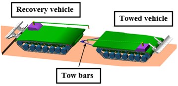
Due to frontal space constraints, it was preferable to carry out towing operation from the vehicle rear side. Both the recovery and towed vehicles were connected by the tow bar assembly, as shown in Fig. 1. The MBD models of both the recovery and towed vehicles were modeled in the rebound position in ATV. Relevant finite element models were taken as reference, in order to obtain required parameters for developing the MBD models of both the recovery and towed vehicles. Both the recovery and towed vehicle models were equipped with 14 road-wheel stations, comprising hydro-gas suspension systems, which were modeled as equivalent non-linear torsional springs and dampers. Vehicle motion was imparted in the form of sprocket angular velocity to the recovery vehicle. It was assumed that the power-pack and brake systems in the towed vehicle had failed. Therefore, no sprocket motion was imparted to the towed vehicle, and the track system had the ability to freely roll without any damage to the suspensions also. Dynamic analyses have been carried out, subsequent to the static equilibrium condition.
2. Finite element modeling and substructuring
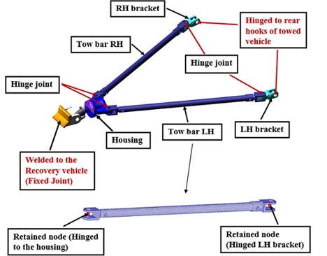
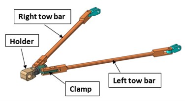
In order to carry out proper assessment of the obstacle negotiation capability, apart from the vehicle dynamic behaviour, it was also required to observe the structural dynamics responses of the tow bars and ascertain that the tow bar stresses were well within safe limits, while negotiating the terrains. Therefore, the tow bars were modeled as flexible bodies using 10 noded tetrahedral finite elements in Abaqus/CAE. Substructuring technique was used, through which information regarding the tow bar natural frequencies and retained nodal degrees of freedom were extracted (shown in Fig. 2). The flexible tow bars, along with their modal information and retained nodal degrees of freedom, are assembled through Adams/Flex in ATV. Suitable joints and contacts were defined between different parts of the tow bar assembly, as shown in Fig. 2.
3. Dynamic simulation over level 1 gradient
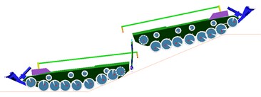
The dynamic analysis of the tracked recovery vehicle, towing another similar weight class vehicle, was carried out over the Level 1 gradient at 5 kmph speed. The recovery and towed vehicle models were positioned at an appropriate distance from the Level 1 gradient (shown in Fig. 3), and started from rest with acceleration @ 0.8 m/s2, in order to achieve 5 kmph speed before encountering the gradient. Snapshot of the tracked recovery and towed vehicles, descending the Level 1 gradient, is indicated in Fig. 4.
Fig. 2Tow bar assembly
The tow bars were also subjected to high oscillating relative planar motion, while descending the gradient because of vehicle inertial effects and consideration of brake failure in the towed vehicle due to which the von-Mises stress magnitudes were high in magnitude towards the end, which caused buckling of the tow rods. Therefore, it was observed that the vehicle was not able to safely carry out the towing operation with another similar weight class vehicle, while ascending and descending the Level 1 gradient even at 2 kmph vehicle speed.
Fig. 3Recovery and towed vehicles before Level 1 gradient

Fig. 4Vehicle behavior while descending Level 1 gradient
4. Simulation over level 2 gradient
Further dynamic analysis was carried out through an iterative approach, in order to arrive at the gradient, safe enough for carrying out the towing operation of recovery vehicle with another similar weight class vehicle. Subsequently, the multi-body analysis was carried out with the recovery vehicle, ascending and descending the Level 2 gradient (lesser than Level 1) at crawling speed of 2 kmph with the towed vehicle. The remaining analysis conditions were similar to that, described in Section 3. The snapshots indicating the dynamics of both vehicles and tow bar while descending the Level 2 gradient, are shown in Figs. 5 and 6.
Fig. 5Vehicle behavior while descending the Level 2 gradient (side view)
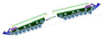
Fig. 6Vehicle dynamics behavior while descending the Level 2 gradient (top view)

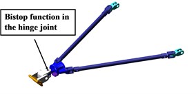
In this case also, relative planar motion was observed between the tow bars, while descending the Level 2 gradient, as observed in Fig. 6. Even at gradients lesser than that of Level 2 also, the phenomenon of relative motion between the tow bars, was observed. Therefore, in order to minimize the relative planar movement, it was proposed to incorporate a bistop contact function between the tow bars (shown in Fig. 7), which represented a stopper arrangement.
Fig. 7Bistop function location
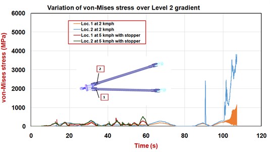
The comparative von-Mises stresses at the tow bar critical locations 1 and 2 with and without the bistop arrangement over Level 2 gradient, have been shown in Fig. 8. It is observed from Fig. 8 that even at a higher vehicle speed of 5 kmph, the maximum von-Mises stresses at locations 1 and 2 are comparatively reduced (about 522 MPa at loc. 2), with the tow bar bistop arrangement. However, without the bistop function, the stresses have high magnitudes and similar order of fluctuations even at 2 kmph vehicle speed.
Fig. 8Structural dynamic responses of tow bars with and without bistop arrangement
Based on the analysis recommendations, the bistop arrangement was practically implemented in the tow bar assembly by introducing an extra C clamp arrangement. Based on the dynamic analysis and experimental evaluation, safe operation of the tow bar assembly was ensured over the Level 2 gradient.
However, with the above arrangement, overall weight and length of the tow bar assembly increased, which caused handling difficulties. Therefore, it was required to further modify the tow bar assembly design with decreased length. Several vehicle dynamic analyses iterations were carried out, through which vital inputs and recommendations were provided to the concerned division for modifying the assembly design, as described in Section 5.
5. Transient dynamic analysis with the modified tow bar assembly
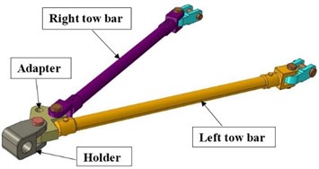
As mentioned in Section 4, the modified tow bar assembly design, arrived at through the detailed vehicle dynamic analyses, is shown in Fig. 9. Integral arrangement is established between the left tow bar and adapter. The right tow bar is assembled with the adapter through pin joint. This arrangement transforms the tow bar assembly to a structure, which would also prevent the relative planar motion, apart from overall length and weight reduction.
Fig. 9Modified tow bar assembly
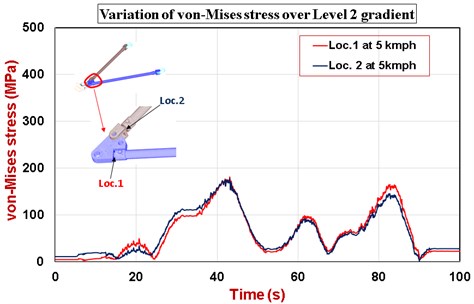
Dynamic analysis was performed over the Level 2 gradient, through which the dynamic behaviour of both the recovery and towed vehicles were observed to be normal. The von-Mises stress variations were captured at critical locations of the modified tow bar assembly, and plotted in Fig. 10. The von-Mises stresses at the tow bar critical locations were much lower (about 181 MPa), compared to that in the previous arrangement, with mass reduction by 25 kg.
Fig. 10Variation of von-Mises stresses on left and right tow bars over Level 2 gradient
Further weight reduction was achieved through design modification of the left and right tow bars with box cross section, as shown in Fig. 11. In this case, the left tow bar is hinged with the adapter having two pins, thereby arresting the relative motion between the left tow bar and adapter. The right tow bar is similarly assembled with the adapter, as described in Fig. 10. With the tow bar modified to box cross section, the von-Mises stress at the tow bar critical locations were observed to be about 121 MPa, with mass reduction by 60 kg with respect to the existing configuration.
Fig. 11Modified tow bar assembly with box section
6. Conclusions
The MBD models of both the military recovery and towed vehicles were developed and integrated with flexible tow bars in ATV through Adams/Flex. Due to formation of a four bar mechanism, relative planar motion was observed in the tow bar assembly while descending the Level 2 gradient, which in turn caused the tow bar stresses to reach beyond allowable limits. Based on the analysis observations, it was proposed to implement additional stopper arrangement in the tow bar assembly in order to limit the relative planar motion, and limit the stress magnitudes within allowable limits. Further design modifications were proposed to be carried out in order to reduce the overall length and weight of the tow bar assembly. In this regard, several dynamic analyses iterations were carried, based on which, vital inputs could be provided to the concerned division for modifying the tow bar assembly design. Dynamic analysis was also carried out with the modified tow bar assembly design over the Level 2 gradient, which revealed lesser magnitudes of tow bar structural response, compared to the previous configuration. The analysis methodology has established a base platform for arriving at the standard operating procedure of towing with a military recovery vehicle, and also for freezing the design configuration of future recovery vehicles.
References
-
Gillespie T. D. Fundamentals of Vehicle Dynamics. Society of Automotive Engineers, USA, 1992.
-
Saayan B., Balamurugan V. Multi-body dynamics analysis of military tracked vehicles using tracked vehicle toolkit of MSC. International Conference on Multi Body Dynamics, Vijayawada, India, 2011, p. 373-383.
-
Paulson I. W. P., Dolovich A. T., Noble S. D. Development of a dynamic simulation model of a towed seeding implement. Journal of Terramechanics, Vol. 75, 2018, p. 25-35.
-
Gurmai L., Kiss P. A comparative study of destructive effects resulting from road profile acting on off-road towed vehicles. Journal of Terramechanics, Vol. 81, 2019, p. 57-65.
-
Mocera F., Nicolini A. Multibody simulation of a small size farming tracked vehicle. Procedia Structural Integrity, Vol. 8, 2018, p. 118-125.
About this article
The authors are grateful to Shri V. Balamurugan, Director, CVRDE, Shri S. Ramesh, Addl. Director (CEAD), Shri R. Murugesan, Scientist ‘G’ and Shri S. Pazhanikumar, Scientist ‘G for extending all the facilities, advice, support and granting permission to publish the paper. The authors also thank CEAD, Special Vehicles division as well as BEML for all their support.
