Abstract
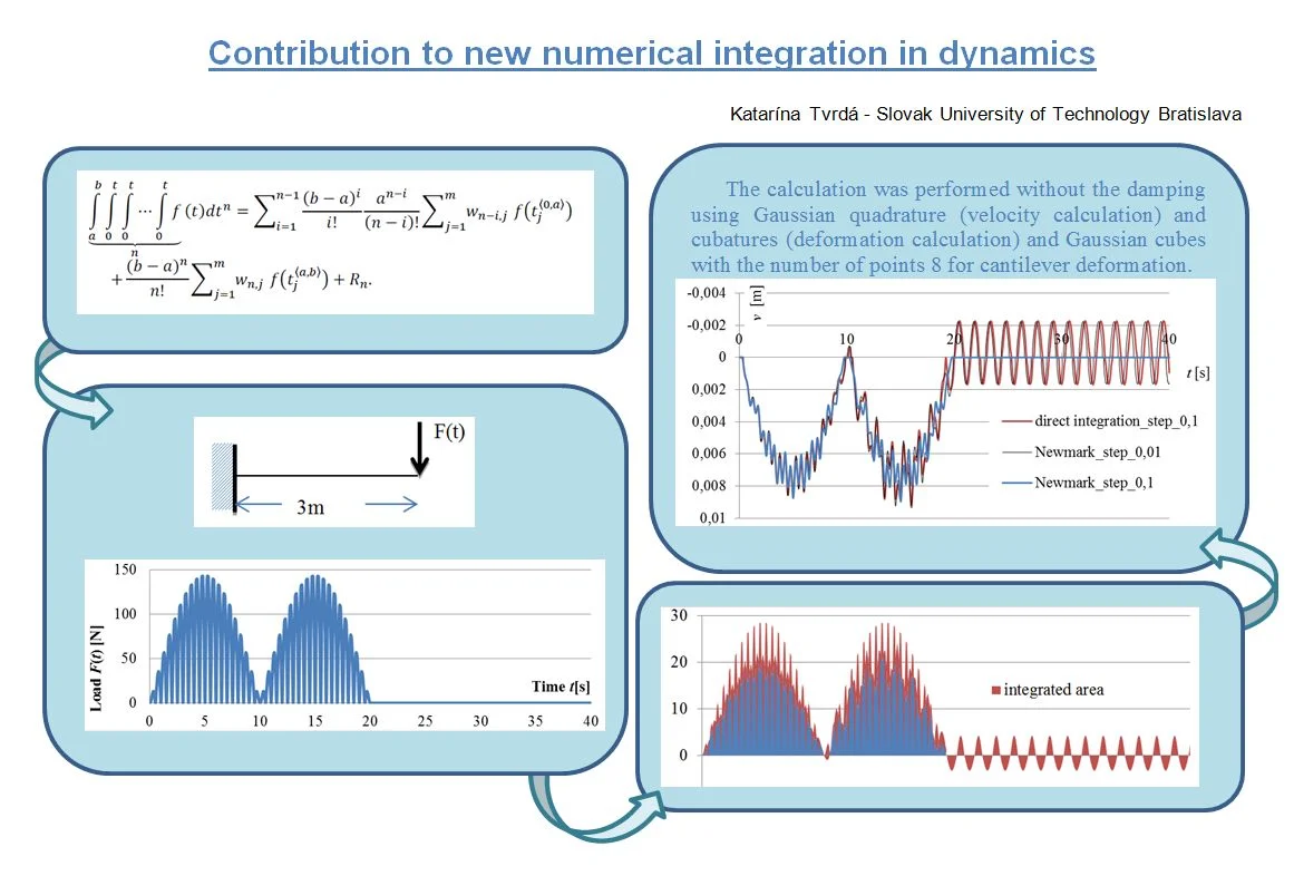
The problem of time integration in the dynamics of building structures is primarily a mathematical problem of the accuracy of the numerical integration of the acceleration time course. All existing methods are trying more or less successfully to master this problem. The best known and most widely used is the Newmark method, which by its very nature is only a trapezoidal rule applied to both acceleration and speed. The most effective method of numerical integration of repeated integrals was introduced mathematically [1], namely the modification of numerical integration methods of the Gaussian type for use on repeated integrals. In this work is introduced their simple use in problem solution of mechanics and dynamics of structures and consequently comparison of the results with the traditional Newmark Direct Time Integration method is presented.
Highlights
- The problem of time integration in the dynamics of building structures is primarily a mathematical problem of the accuracy of the numerical integration of the acceleration time course.
- The best known and most widely used is the Newmark method, which by its very nature is only a trapezoidal rule applied to both acceleration and speed.
- The most effective method of numerical integration of repeated integrals was introduced mathematically.
- The modification of numerical integration methods of the Gaussian type was used on repeated integrals.
- The present paper shows the possibilities of a new method of numerical integration of repeated integrals and their practical use in nonlinear calculations in statics and dynamics of structures.
1. Introduction
The transformation of repeated integrals into simple ones is analytically derived in published work [1]. Simultaneously there is also listed a modification of some existing numerical methods for their efficient solution.
In principle, it is possible to substitute each repeated integral with borders [a,b] by a single integral, or integrals. In the numerical solution of the integral, this means transformation to a simple sum of multiples of weights wi,j and functional values f(tj) in a suitable choice of the nodes tj Eq. (1), where n is the number of repeated integrals and m is the number of nodes. The detailed explanation of the modified Gaussian type numerical methods for repeated integrals the reader can find in [1]. The final expression has the form:
+(b-a)nn!∑mj=1wn,jf(t〈a,b〉j)+Rn.
Seeing that it is a Gaussian quadrature that has been splitted and transformed by Cauchy’s theorem [2] to solving repeated integrals [1], the error term Rn is then according to [4]:
From a practical point of view it is important to note that the standard Gaussian quadrature with the m number of points accurately integrates all polynomial functions of the order of equal and less than (2m-1). Derivation [1] implies that with each repeated integral the accuracy decreases by one. Thus, the polynomial accuracy of common Gaussian cubatures with m number of points is (2m-n).
The Eq. (1), as shown below, allows us to solve numerically the technical tasks whose relationships are defined by the higher order integrals (hence the problem of forced vibration, too) by applying simple algebraic operations.
2. Illustrative use of modified Gaussian integration
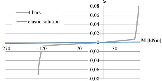
Let us consider the real concrete cantilever in Fig. 1, with a cross-section 0,3×0,5 m and reinforced by 4 tension bars with dependence between torque and the resulting strain deformation (curvature κ(M)).
This dependence is definitely non-linear (Fig. 2) and can be easily determined for each particular cross-section.
Fig. 1Cantilever loaded by a force F= 30 kN
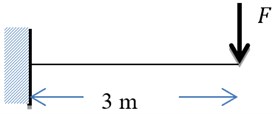
Fig. 2Graph of the dependence of curvature κ from the moment M
The deflection is defined by Eq. (3) [3]:
This integral is not analytically solvable in general. Our solution from [1] can due to Eq. (1) substitute the integral Eq. (3) with sum Eq. (4), while the chosen number of nodes m gives us the polynomial accuracy of the approximation (2m-2) for twice repeated integral, which gives us enough possibilities to solve with sufficient precision:
Relation Eq. (4) contains only one sum compared to relation Eq. (1) because of the integration boundary a was chosen zero and therefore the whole first sum of Eq. (1) is equal to zero. The entire solution, including the weights for Gauss-Legendre cubature of 8th order, is shown in Table 1.
As it can be seen from Table 1, by applying Eqs. (1) to (3) we have received a simple relationship Eq. (4) on the basis of which at specified nodes (prescribed by the given method), the curvature values for 4 bars of reinforcement (or even in the linear solution) are just multiplied by the relevant weight, and their sum is multiplied by the coefficient (in this particular case L2/2).
Table 1Displacement of cantilever with material nonlinearity
Points [m] | Moment [kNm] | Weight [–] | 4 bars | Elastic solution | ||
x(i) | w2,i | κ(M) | κ(M)w2,i | κ(M)/10-5 | κ(M)w2,i | |
0,059565 | –88,213 | 0,099218636439 | –0,0038153 | –0,0003786 | –85,5399210 | –8,487154324.10-5 |
0,305000 | –80,850 | 0,199772274907 | –0,0034939 | –0,000698 | –78,3999917 | –1,5662144703.10-4 |
0,711701 | –68,649 | 0,239284827746 | –0,0029615 | –0,0007087 | –66,5686870 | –1,5928876797.10-4 |
1,224848 | –53,254 | 0,214606276760 | –0,0022929 | –0,0004921 | –51,6407844 | –1,1082436469.10-4 |
1,775152 | –36,745 | 0,148077506617 | –0,0015791 | –0,0002338 | –35,6319429 | –5,276289257.10-5 |
2,288299 | –21,351 | 0,074421818131 | –0,000916 | –6,817.10-5 | –20,7040403 | –1,540832321.10-5 |
2,695000 | –9,150 | 0,022608759545 | –0,0003931 | –8,888.10-6 | –8,8727355 | –2,00601544.10-6 |
2,940435 | –1,787 | 0,002009899851 | –7,680E-05 | –1,544.10-7 | –1,7328063 | –3,482767.10-8 |
Σκ(M)w2,i | –2,5883.10-3 | –5,8181818182×10⁻⁴ | ||||
Displacement [m] = | 0,011647 | 2,6181818181818×10⁻³ | ||||
In such a simple way are obtained the result of repeated integral, in this case deflection of a structure, with the physical nonlinear behavior of the material for given cross-sectional reinforcement as well as for the elastic solution according to Fig. 2. The precision of Gaussian numeric cubature of 8th order responds to result of the best approximation of the polynomial order 14, what means that due the numeric cubature we get the exact solution of deflection of elastic cantilever to 15 digits, where EI= 103125 kNm2. The same deflection result 2,6181818181818×10⁻³m was obtained from an analytical solution from the theory of elasticity, thereby confirming the good convergence of the scheme used. More about the solution of repeated integrals can be found in the work [1].
3. Analysis of the oscillation of the reinforced concrete cantilever
3.1. Direct integration of the d’Alembert’s differential equation
In calculating of forced oscillation and time response of structures, various methods of direct integration of the d’Alembert’s differential equation at discrete time points are often used [5]. In Eq. (5) it is presented in the form for a physical nonlinear material:
where φ(v(t)) is stiffness force, C is damping, mmass is structural mass, v(t) is displacement and F(t) is applied dynamic force.
Till now, the most common method is the classic Newmark method [6], which is the extension of the trapezoidal rule to the second integral. Its biggest disadvantage is that it accurately integrates max. linear accelerations. This means that to reduce the aberrance with a significantly variable dynamic load that cannot be described by linear acceleration requires a very dense division. Using [1], we can pre-determine the accuracy of integration, depending on step length, load function, acceleration approximation, and desired accuracy result, if necessary, by selecting the type and order of numerical integration. From the point of view of the precision of the calculation of the most critical quantity, the accuracy of the acceleration approach within the calculation interval time step becomes more accurate. This can be improved by a number of ways, such as interpolating over multiple intervals, by adding known derivate values from the previous calculation at the beginning of the interval or selecting other iterated parameters within the time interval.
3.2. Dynamic analysis of the reinforced concrete cantilever
Let us consider the cantilever loaded according to Fig. 1, with four bars, the dynamic load being defined by the time-dependent function:
The curve of the dynamically changing force in the time from 0 to 40 seconds according to the relationships Eq. (6) and (7) is shown in Fig. 4.
Fig. 4The time dependence diagram of the dynamic load

The calculation was performed without considering the damping using Gaussian quadrature (velocity calculation) and cubatures (deformation calculation) with the number of points 16 for time integration, and Gaussian cubes with the number of points 8 for cantilever deformation.
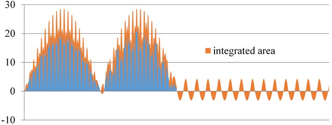
Fig. 5Integrated area for velocity and displacement calculation
The time step 0,1 sec was chosen for calculation. At each time step we estimate the stiffness force φ(v(t)) acting at the point of the force F(t) and the concentrated mass mmass.
When the cantilever is loaded by this force, the corresponding deformation v1 and ¨v1 is obtained (time step method).
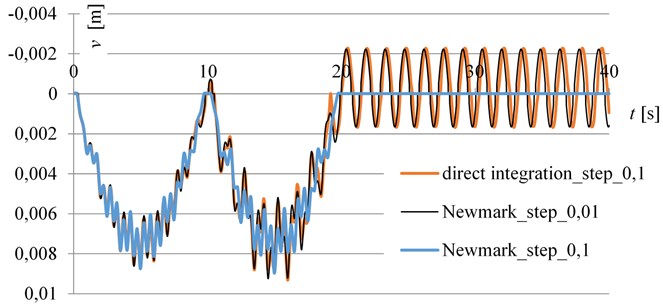
Within each time step, we must integrate part the area of Fig. 5, which is very irregular. According to [1], we integrate this area within each time interval, which allows us to increase the time step while maintaining the required accuracy. The deflection results are shown in Fig. 6.
It is clear from the results that the integration area of Fig. 5 is very fragmented and the linear Newmark integration for step 0,1 does not have sufficient accuracy of the calculation (see Fig. 6).
The result-comparable calculation by the Newmark’s method had to be accomplished with a step of 0,01, that is 10 times more divisive than our present solution.
The irregular shape of the wave after load termination is due to the material non-linearity.
Fig. 6The time – deflection diagram
4. Conclusions
The present paper shows the possibilities of a new method of numerical integration of repeated integrals [1] and their practical use in nonlinear calculations in statics and dynamics of structures. Compared to the methods used so far, their use is simple and the choice of the correct integration method (Newton-Cotes, numerical integration of Gaussian type) and order can optimize the requirements for integration accuracy with regard to the efficiency of the effort. This was not enabled by the methods so far. The advantage of this method is that the larger computation step can be implemented, but on the other hand, there is an increased risk of aliasing [7, 8]. Therefore, it is necessary to verify the result by further calculations with a reduced time step length for at least two waves.
References
-
Tvrdá K., Minárová M. Computation of definite integral over repeated integral. Tatra Mountains Mathematical Publications, Vol. 75, 2018, p. 1-14.
-
Folland G. B. Advanced Calculus. Prentice Hall, 2002.
-
Dický J., Mistríková Z., Sumec J. Elasticity and Plasticity in Civil Engineering. Slovak University of Technology, 2005.
-
Abramowitz M., Stegun I. Handbook of Mathematical Functions. Dover Publications, Inc. New York, 1972.
-
Koloušek V., et al. Civil Structures Stressed by Dynamic Effects. Bratislava SNTL, 1967, p. 1055, (in Czech).
-
Sokol M., Tvrdá K. Dynamic of Buildings. Bratislava, 2011.
-
Don P. M., Arun N. N. Reconstruction filters in computer graphics. Computer Graphics, Vol. 22, Issue 4, 1988, p. 221-228.
-
Dale R. D. Numerical Methods for Wave Equations in Geophysical Fluid Dynamics. Springer, Science+Business Media, New York, 1998.
About this article
The work has been supported by the grant from Grant Agency of VEGA in Slovak Republic No. 1/0412/18.
