Abstract
Imaging for damage in plate structure by Lamb waves is one of the most effective methods in the field of structural health monitoring. In order to improve the accuracy of damage localization, a novel method is proposed to modify damage exponent probability imaging algorithm based on delay-and-sum imaging by using time reversal Lamb waves. A new probability distribution function is introduced to improve the damage index probability method and is combined with delay-and-sum method for damage localization. Experimental results on aluminum plate show that the hybrid algorithm achieves better accuracy of damage location and imaging quality than the conventional delay-and-sum method.
1. Introduction
Structural health monitoring (SHM) has been an important research field in material integrity nondestructive testing (NDT). As a special ultrasonic wave, Lamb wave has been widely used in the health monitoring of thin plate or shell structure in recent years because of its long propagation distance and low energy attenuation. When the Lamb wave propagates through the defect of the structure, the scattering phenomenon occurs. The damage can be regarded as a secondary source, and the scattered signal propagates in all directions, which pass through the defect again and form a larger echo [1-3].
Time reversal based on the principle of acoustic reciprocity can focus energy in space and time, through which the position of sound source can be obtained, and the signal of sound source can be reconstructed. Ing and Fink [4] compensate the dispersion of Lamb wave automatically by time reversal method. The experiments show the spatial and temporal focusing characteristics of Lamb wave. Wang et al. [5] synthesizes time reversal and synthetic aperture techniques for damage image in structures.
Damage Index (DI) is proposed to characterize changes caused by structural damage and identify the existence of the damage. Wang D et al. [6] proposes a probabilistic imaging algorithm for damage index based on sensor network. Wang et al. [5] proposes a delay-and-sum (DAS) algorithm which effectively images the received signals but results in artifacts for multiple defects. Sohn et al. [2] studies the relationship between the damage condition and the consistency of shape of the source and the reconstructed signal and uses the damage index to characterize the damage degree. Hay et al. [7] proposes a reconstruction algorithm for probabilistic inspection of damage (RAPID), which is a probability-based damage imaging method.
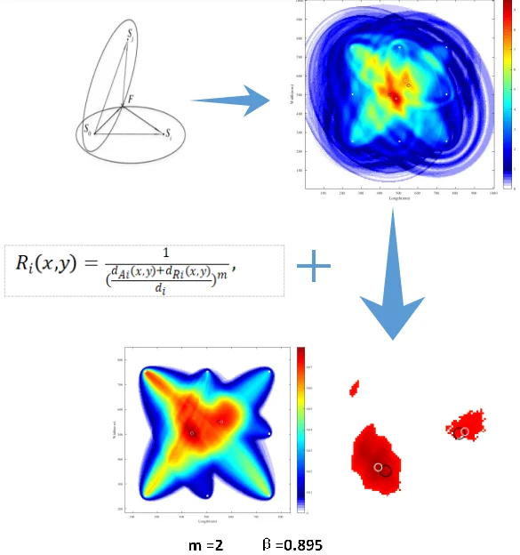
In this paper, we propose a modified damage index probability imaging algorithm based on delay-and-sum imaging algorithm by synthesizing time-reversed Lamb waves. A new probability distribution is investigated to better describe the probability of defect occurrence. The validity of the new algorithm is verified by experiments and the damage location is accurately displayed.
2. Principle of time reversal method
Time reversal means that the receiver receives a signal transmitted by the sound source in time domain, and then transmits the signal from the corresponding receiving sensor, that is, first to the second, and then to the first. By focusing energy in space and time, the position of sound source can be obtained and the reconstruction of signal from sound source can be realized.
We refine the above process. First, the electrical signal is converted to mechanical strain through the transmitter, where other factors are ignored, and only piezoelectric conversion is considered [8]:
where ω is angular frequency, ka(ω) is electro-mechanical efficiency coefficient, V(ω) is driving voltage, and ε(ω) is mechanical strain. The Lamb waves generated by the mechanical strain propagates in the medium, and the signals received at the receiver are as follows:
where ks(ω) is mechanical-electro efficiency coefficient and G(ω) is a transfer function. The time reversal of the signal VB(ω) is equivalent to the complex conjugation V*B(ω) in frequency domain. Then the signal that reverses the time is transmitted from the receiver, at which point the signal received at the transmitter is the refactoring signal:
=ks(ω)⋅G(ω)⋅ka(ω)⋅k*s(ω)⋅G*(ω)⋅k*a(ω)⋅V*(ω)
=T(ω)⋅K(ω)⋅K*(ω)⋅V*(ω),
where G(ω) is the same transfer function as in Eq. (2) based on the reciprocity of elastodynamics [9]. For simplification, let (ω)=G(ω)⋅G*(ω) and K(ω)=ka(ω)⋅ks(ω).
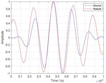
For thin plate without defects, G(ω) is a constant, so the reconstructed signal is similar to the original signal. For the case of thin plate with defect,G(ω) is nonlinear, and the frequency dispersion occurs, so the reconstructed signal is distorted compared with the excitation signal after the final time reversal [10], as shown in Fig. 1. In this paper, the reconstructed signals are normalized and enveloped.
Fig. 1Reconstruction signal dispersion
3. Proposed method
3.1. Delay-and-sum imaging
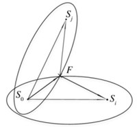
The delay and sum imaging algorithm is a combination of elliptic imaging algorithm and time reversal theory. The position of damage is the intersection of multiple ellipses as shown in Fig. 2. In detection region with damage, the time of the point X(x,y) can be calculated by Eq. (4):
where S0 is the transmitting sensor, Si is the ith receiving sensor, and cg is Lamb wave group velocity.‖S0X‖ is the distance from S0 to X(x,y).‖SiX‖ is the distance from Si to X(x,y). The pixel value of point X(x,y) can be calculated by Eq. (5) for a known time reversal of the reconstruction signal:
where I(x,y) is the damage imaging value of the position X(x,y), N is the number of the signals, Ai is a coefficient for balancing the transducers’ output,t(x,y) is the time from point X(x,y) to a set of transmitter-receive pairs, fi is the reconstruction signal, and ts is delay time.
Fig. 2Delay-and-sum imaging method
3.2. Improved damage index probability imaging
According to time reversal method, the damage index of a sensing path can be defined as the similarity between the reconstructed signal from this transmitting - receiving pair and the original excitation signal. There are several methods to calculate the damage index of a sensing path, and in this paper the classical method [11] is used. The damage index reflects the influence of defect on the sensing path, as follows:
where i denotes the ith damage sensing path, t0 and t1 are the signal start time and the end time, respectively. The probability of defect occurrence at a certain point can be reconstructed from a DIi mapped probability distribution function. For N sensing paths in detection region, the damage probability of each pixel X(x,y) can be expressed as Eq. (7):
where P(x,y) is the defect probability at position (x,y) within detection region,pi(x,y) is the estimation from theith sensing path, and Wi[Ri(x,y)] is the probability distribution function. In this paper, the distribution function is improved on the basis of the study of Sheen et al. [11]. The relative distance between the transmitter-receiver pair Ri(x,y) is defined as:
where dAi is the distance from X(x,y) to the transmitter in the ith sensing path. Similarly, dRi is the distance to the receiver. di is the distance from the transmitter to receiver. m is an index of distribution decline rate which determines the decreasing rate of damage index in elliptical distribution. By controlling the descent rate of the distribution function, the corresponding distribution boundary is controlled by Eq. (9):
where β is a shape parameter of a certain sensing path, which determines the distribution boundary. The best distribution function in DAS weighted damage probability index algorithm is explored for the optimum combination of m and β.
3.3. Improved DAS weighted damage probability imaging
In DAS method, damage is located at where the amplitude of ellipse is maximum. Therefore, the distribution function of damage probability is further improved. According to Eq. (5) and Eq. (9), the improved distribution function is expressed as Eq. (10):
So the overall image by the proposed algorithm is as follows:
4. Experiment and results
4.1. Experimental setup
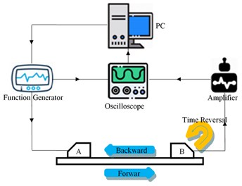
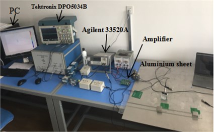
Experimental instrument consists of a host computer, an arbitrary waveform signal generator (Agilent 33520A), an independently designed active signal amplifier (based on the TI op amp chip OPA657), and a 4-channel oscilloscope (Tektronix DPO5034B). The system is shown in Fig. 3.
Fig. 3Schematic illustration of experimental setup
a) Experimental system
b) Experiment set-up
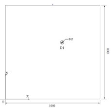
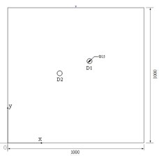
Two pieces of 1000×1000×1.5 mm3 aluminum plate with a single circular hole defect and double circular hole defects, respectively, are used in the experiment. The diameter of all the defects is 15 mm. Taking the lower left corner of aluminum plate as the origin, the coordinate of single circular hole defect is (550, 550), the coordinates of double circular hole defects are (550, 550) and (450, 500), and the unit is mm, as shown in Figs. 4(a) and 4(b).
Fig. 4Diagram of sample plates
a) Single flaw sample
b) Double flaws sample
c) Sensing paths layout
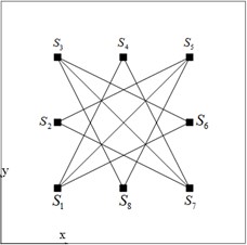
At the same time, the strategy of limited detection region is used to physically avoid the influence of edge reflection. The detection region is divided into 400×400 grids with an area of 2.5×2.5 mm2 for each grid. The arrangement of eight sensors (S1~S8)is shown in Fig. 4(c), with coordinates of (mm):S1(250,250), S2(500,250), S3(750,250), S4(500,750), S5(750,750), S6(750,500), S7(750,250), and S8(500,250). The sensor (Bat brand by Changzhou Ultrasonic Electronics Co. Ltd.) with an oblique probe with a dip angle of 30° is used in the experiment.
The attenuation of Lamb wave is inevitable in the transmission process. In order to reduce the attenuation on the reconstructed signal, a 5-cycle Hanning window-modulated sine wave is used as the excitation signal, and the frequency is 500 kHz.
The time reversal reconstruction signal of all the paths as shown in Fig. 4(c) is obtained. All signals are normalized and enveloped. The parameter m is set to 1/2, 1 and 2, and the optimum imaging combination is found by the experimental regulation of parameter β.
4.2. Data processing and experimental results
According to Eq. (6), the damage index along different sensing paths for single flaw is shown in Table 1, and for double flaws is shown in Table 2. Six sensing paths along which the amplitudes of reconstructed signals are the first six largest are selected for imaging by Eq. (11).
Table 1Damage index of single flaw
Paths | S4-S7 | S1-S5 | S1-S6 | S3-S6 | S3-S7 |
DI | 0.1402 | 0.1336 | 0.1330 | 0.1287 | 0.1242 |
Paths | S3-S8 | S2-S5 | S1-S4 | S2-S7 | S5-S8 |
DI | 0.1212 | 0.1202 | 0.1189 | 0.1160 | 0.1010 |
Table 2Damage index of double flaws
Paths | S4-S7 | S1-S5 | S3-S7 | S1-S4 | S3-S6 |
DI | 0.1695 | 0.1450 | 0.1429 | 0.1386 | 0.1322 |
Paths | S3-S8 | S1-S6 | S2-S7 | S2-S5 | S5-S8 |
DI | 0.1299 | 0.1228 | 0.1192 | 0.1167 | 0.1129 |
For single-flaw sample, with distribution drop rate parameter m = 1/2, 1and 2, the best shape parameter is calculated as β= 0.974, 0.948 and 0.895, respectively. The corresponding images are shown in Figs. 5(a), 5(b) and 5(c), where the same black circle is the actual damage position, and the white circle is the damage location estimated by the proposed algorithm. It is seen that the three sets of parameter combination of m and β show a good localization. The estimated damage position is (557.5, 562.5). In order to facilitate observation, A 90 % threshold value is used for Fig. 5(c) for better illustration, and the enlarged image is as shown in Fig. 5(d), where the black circle is the actual damage position, and white circle is the estimated damage position with the largest pixel value.
For double-flaw sample, the parameter combination of m and β are the same as for single-flaw. The images for double-flaw are shown in Fig. 6(a), 6(b) and 6(c). For m = 1/2 and β = 0.974, the estimated positions of the two defects are (560, 550) and (435, 512.5), respectively. For m= 1 and β = 0.948, the estimated position of damage 1 is (560, 550); there are two possible positions for damage 2, which are (435, 512.5) or (440, 505). For m = 2 and β = 0.895, the image of double flaws shows the best localization. The estimated positions of double flaws are (560, 550) and (440, 505), respectively. An enlarged image by applying a 90 % threshold value to Fig. 6(c) is shown in Fig. 6(d), where the black circle is the actual damage position, and the white circle is the estimated damage position with the largest pixel value.
The proposed method is compared with DAS imaging using the same setting. The images of DAS method are shown in Fig. 7(a) and 7(b).
Fig. 5Imaging results of single-flaw sample
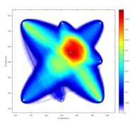
a)m = 1/2,β = 0.974
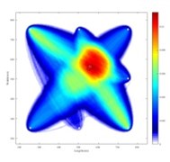
b)m = 1,β = 0.948
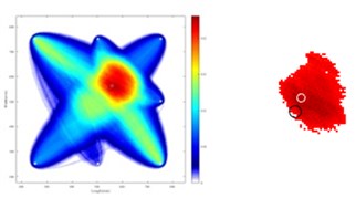
c)m = 2,β = 0.895
Fig. 6Imaging results of double-flaw sample
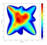
a)m = 1/2,β = 0.974
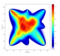
b)m = 1,β = 0.948
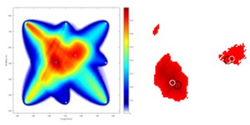
c)m = 2,β = 0.895
Fig. 7Imaging results of DAS
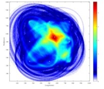
a) Single-flaw sample
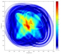
b) Double-flaw sample
The errors of our proposed method and DAS method for single flaw and double flaws sample are listed in Table 3. Generally, our proposed method has a better damage localization than DAS method for both single-flaw and double flaw cases. For parameter combination of m= 2 and β= 0.895, our proposed method shows the most accurate damage position.
Table 3Error of our proposed algorithm and DAS method
Algorithm | Single defect | Double defects | |
D1 | D1 | D2 | |
Our proposed method (m= 2,β= 0.895) | 14.58 mm | 10.00 mm | 11.18 mm |
Delay-and-sum | 19.04 mm | 29.15 mm | 40.31 mm |
5. Conclusions
Based on the delay-and-sum weighted damage index probability method, the proposed method improves the distribution function by introducing a distribution drop rate parameter m. The time reversal lamb wave is used to focus the scattering energy, and the damage index is obtained by calculating the reconstruction deviation from the original signal. Experimental result shows that the method has better location accuracy compared with the delay-and-sum weighted damage index probability method, which validates the efficiency of the proposed method, and the best parameter combination are distribution drop rate parameter m = 2 and the shape parameter β = 0.895. In future studies, more precise positioning can be achieved through more accurate group velocity measurements.
References
-
Xu B., Giurgiutiu V. Single mode tuning effects on lamb wave time reversal with piezoelectric wafer active sensors for structural health monitoring. Journal of Nondestructive Evaluation, Vol. 26, Issues 2-4, 2007, p. 123-134.
-
Park H. W., Kim S. B., Sohn H. Understanding a time reversal process in Lamb wave propagation. Wave Motion, Vol. 46, Issue 7, 2009, p. 451-467.
-
Liqiang G., Weiguang Z., Yifeng L. Research on hybrid techniques of time-reversal ellipse location and tomographic imaging of lamb wave. Journal of Nanjing University (Natural Science), 2019.
-
Ing R. K., Fink M. Time-reversed Lamb waves. IEEE Transactions on Ultrasonics, Ferroelectrics and Frequency, Control, Vol. 45, Issue 4, 1998, p. 1032-1043.
-
Wang C. H., Rose J. T., Chang F. K. A synthetic time-reversal imaging method for structural health monitoring. Smart Materials and Structures, Vol. 13, Issue 2, 2004, p. 415-423.
-
Wang D., Ye L., Lu Y., et al. Probability of the presence of damage estimated from an active sensor network in a composite panel of multiple stiffeners. Composites Science and Technology, Vol. 69, Issue 13, 2009, p. 2054-2063.
-
Hay T. R., Royer R. L., Gao H., et al. A comparison of embedded sensor Lamb wave ultrasonic tomography approaches for material loss detection. Smart Materials and Structures, Vol. 15, Issue 4, 2006, p. 946.
-
Su Z., Ye L. Identification of damage using lamb waves: from fundamentals to applications. Lecture Notes in Applied and Computational Mechanics, Springer-Verlag London, 2009.
-
Crawley E. F., De Luis J. Use of piezoelectric actuators as elements of intelligent structures. AIAA Journal, Vol. 25, 1987, p. 1373-1385.
-
Sohn H., Park H. W., Law K. H., et al. Damage detection in composite plates by using an enhanced time reversal method. Journal of Aerospace Engineering, Vol. 20, Issue 3, 2007, p. 141-151.
-
Seyedpoor S. M., Montazer M. A damage identification method for truss structures using a flexibility-based damage probability index and differential evolution algorithm. Inverse Problems in Engineering, Vol. 8, 2015, p. 1303-1322.
Cited by
About this article
This work was supported by the National Natural Science Foundation of China with Grant Nos. 61671285.
Qingwei Xia was responsible for proposal and writing of the ideas of the thesis. Yanyan Liu was responsible for guidance of the thought of the paper and the revision of the paper. Yu Lu constructed experimental instrument and the basis of imaging code. Shuhao Cao was responsible for discussion on experimental data acquisition and thinking. Hanfei Zhang was responsible for a cooperative study on the feasibility of the ideas of the thesis. Shiwei Ma was responsible for the guidance of the large-direction of the paper and the gatekeeper of the paper’s innovation point.

