Abstract
Vibration monitoring of blasting excavation of drainage tunnel in Lufeng Nuclear Power Plant is carried out and the data of blasting vibration is analyzed in this paper. The results show that: (1) The vertical vibration velocity of the rock mass is greater than the horizontal radial and horizontal tangential vibration velocity (2) The blasting vibration velocity of rock mass decreases with distance, which is affected by rock structure and explosive quantity. The monitoring research in this paper has guiding significance for vibration prediction and control in tunnel blasting excavation.
1. Introduction
Slope instability refers to the occurrence of cracks, loosening and sliding in the slope after blasting or earthquake, which seriously affects the stability of the slope [1, 2]. In the dynamic problems of rock engineering, the common dynamic loads are engineering blasting, earthquake, locomotive and mechanical vibration [3, 4]. In practical engineering, blasting vibration is more common than ground motion, and rock damage caused by blasting is more complex [5].
In this paper, blasting vibration monitoring is carried out in the construction site. The influence of blasting vibration on rock slope and the law of vibration attenuation in practical engineering are studied [6-8].
2. Overview of Lufeng nuclear power station project
2.1. Engineering survey
The drainage tunnel of the drainage tunnel project of No.1 and No.2 units of Lufeng Nuclear Power Plant is 3512.336 m, of which mileage SSK0+000.000-SSK0+736.000 (hereinafter referred to as ‘1# drainage tunnel’), SSK2+620.000-SSK3+512.366 (hereinafter referred to as ‘2#’ The drainage tunnel is constructed by the mining method with a length of 1628.336 m. The longitudinal section of the drainage tunnel is designed to have a maximum longitudinal slope of 31.25 ‰, a minimum longitudinal slope of 1.66 ‰, and a minimum buried depth of 12 m. The effect diagram of the nuclear power plant is shown in Fig. 1.
2.2. Design parameters
According to the design drawings of drainage tunnels, the classification of surrounding rocks of drainage tunnels is shown in Table 1.
The parameters of excavation support for different types of surrounding rock are as follows:
Type II-A section is used in grade II surrounding rock section. The tunnel excavation section span is 8060 mm and height is 8080 mm. The initial lining is C25 shotcrete with 80 mm thickness, anti-seepage grade P6, single layer Ф8 steel mesh, 250 mm×250 mm spacing, 2.5 mm long diameter 25 mm cartridge coil anchor (HRB400) in a 120-degree range of vault, and 1.2 m×1.2 m spacing.
Table 1Classification of surrounding rock of drainage tunnel
Serial number | Mileage | Length (m) | Surrounding rock category |
1 | SSK0+150.000-SSK0+211.000 | 61 | ⅤA-2 |
2 | SSK0+211.000-SSK0+330.000 | 119 | ⅡA |
Fig. 1Lufeng nuclear power project sketch map

V-A-2 section is used in grade V surrounding rock section. The tunnel excavation section spans 8500 mm and its height is 8650 mm. The initial lining is made of C25 shotcrete with a thickness of 300 mm, impermeability grade P6, 4Ф25 limb grille steel frame (spacing 0.6 m/hull) and double Ф8 steel mesh (spacing 200 mm×20 mm). A hollow grouting anchor pipe of 4.0 m long Ф25 is set in the 235-degree range of the vault roof, with a spacing of 1.0 m×1.0 m (longitudinal×circumferential). Full-section curtain grouting, grouting using forward grouting, each grouting section length of 30 m, grouting material using C-S (ordinary cement-water glass) double slurry, water-cement ratio of 1:1, C:S (mass ratio) of 1:1, the first grouting pressure should be adjusted according to the field test, the remaining grouting hole pressure is greater than 2 MPa.
3. Safety threshold of blasting vibration and vibration monitoring system
3.1. Control standard for newly poured concrete and cut-off wall
1. The age of concrete is 1-3 days, and the peak velocity of particle vibration is not more than 1.5 cm/s.
2. The age of concrete is 3-7 days, and the peak velocity of particle vibration is not more than 2.5 cm/s.
3. The age of concrete is 7-28 days, and the peak velocity of particle vibration is not more than 5 cm/s.
3. The peak velocity of particle vibration is not more than 2.5 cm/s when the reinforcing range of cut-off wall is about 18 meters away.
4. The peak velocity of particle vibration is not more than 7.5 cm/s within 18 meters of the reinforcement range of the cut-off wall.
3.2. Monitoring system
This project adopts TC-4850 self-recording instrument vibration testing system. The blasting vibration self-recording instrument (TC-4850) is equipped with acceleration and speed sensors, which can replace the traditional monitoring system of the tape recorder and cable transmission signal in various complex environments.
According to the characteristics of this project, the main contents of vibration monitoring include monitoring the impact of blasting construction on high rock slope, monitoring the impact of blasting construction on newly poured concrete, and monitoring when blasting construction may cause damage to adjacent earth buildings. Each measuring point is equipped with horizontal radial, horizontal tangential and vertical velocity sensors.
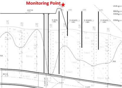
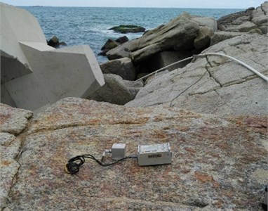
This test is mainly aimed at monitoring blasting vibration of rock mass on the top of the cut-off wall in high rock slope during tunnel blasting excavation, as shown in Fig. 2.
Fig. 2Blasting vibration monitoring point position and instrument layout diagram

a)

b)
4. On-site monitoring results and analysis of blasting vibration
By analyzing the results of blasting vibration monitoring in the site, the following results are drawn:
Table 2 shows the monitoring results of rock mass vibration at the top of the cut-off wall of high rock slope during 15 blasting excavation of tunnel construction at different locations. The total and maximum explosive quantities, horizontal distance between monitoring point and explosion source and vibration velocity in three directions are listed in the table. It is obvious from the table that the vertical velocity of the rock mass is greater than the horizontal radial and horizontal tangential velocity. Moreover, the times when the vibration velocity reaches its maximum in three directions are not the same, due to the difference of propagation velocity between the shear wave and longitudinal wave in rock mass. All other on-site monitoring results illustrate this phenomenon.
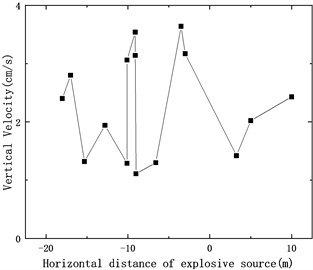
Fig. 3 shows that the vertical vibration velocity of rock mass varies with the location of the explosion source. From the figure, it can be seen that the overall trend of the variation of the vibration velocity is that the vibration velocity decreases with the horizontal distance between monitoring point and explosion source. However, due to the influence of natural conditions of rock strata and explosive charge quantity, the vibration speed will fluctuate to a certain extent. The law of vibration attenuation observed in this paper can be applied to the prediction and control of blasting vibration in tunnel excavation engineering so as to reduce the damage to rock mass and buildings caused by blasting.
Table 2Monitoring results of peak vibration velocity and main frequency of blasting in tunnel construction
Number | Total explosive dose/kg | Maximum explosive charge/kg | Horizontal distance/m | Radial velocity /cm.s-1 | Radial frequency /Hz | Tangential velocity /cm.s-1 | Tangential frequency /Hz | Vertical velocity /cm.s-1 | Vertical frequency /Hz |
1 | 120 | 8.562 | –18 | 0.63 | 35.7 | 0.40 | 31.3 | 2.4 | 26.3 |
2 | 120 | 8.562 | –17 | 0.96 | 27.8 | 0.45 | 21.7 | 2.8 | 16.7 |
3 | 36 | 7.852 | –15.3 | 0.76 | 27.8 | 0.99 | 15.2 | 1.32 | 14.7 |
4 | 120 | 8.562 | –12.8 | 0.90 | 14.7 | 0.51 | 25.0 | 1.94 | 14.7 |
5 | 29 | 8.62 | –9.1 | 0.48 | 50.0 | 0.37 | 62.5 | 0.54 | 38.5 |
6 | 72 | 6.86 | –10.1 | 0.45 | 45.5 | 0.32 | 35.7 | 1.29 | 38.5 |
7 | 96 | 7.86 | –10.1 | 1.45 | 12.5 | 0.81 | 9.6 | 3.06 | 30.0 |
8 | 120 | 8.65 | –9.1 | 0.94 | 12.5 | 1.17 | 15.6 | 3.14 | 23.8 |
9 | 72 | 6.86 | –9 | 0.28 | 55.6 | 0.25 | 33.3 | 1.11 | 31.3 |
10 | 56 | 9.792 | –6.6 | 0.42 | 45.5 | 0.30 | 20.8 | 1.30 | 26.3 |
11 | 72 | 7.65 | –3.5 | 1.14 | 13.9 | 0.84 | 45.5 | 3.64 | 26.3 |
12 | 72 | 7.65 | –3 | 2.17 | 31.3 | 2.33 | 18.5 | 3.17 | 21.7 |
13 | 120 | 10.8 | 3.27 | 2.30 | 33.3 | 1.73 | 25.0 | 1.42 | 41.7 |
14 | 192 | 14.9 | 5 | 1.30 | 13.5 | 0.45 | 20.0 | 2.02 | 19.2 |
15 | 192 | 14.9 | 10 | 1.67 | 13.9 | 0.84 | 11.9 | 2.43 | 38.5 |
Fig. 3Vertical vibration velocity variation with explosion source location

5. Conclusions
In this work, blasting excavation vibration of drainage tunnel in Lufeng Nuclear Power Plant construction project is monitored in real time. The results obtained show that the vertical vibration velocity of the rock mass is greater than the horizontal radial and horizontal tangential vibration velocity, in which the times when the vibration velocity reaches its maximum in all directions are not the same. In terms of attenuation law, the overall trend of the vibration velocity is that the vibration velocity gradually becomes smaller as the distance increases, influenced by natural conditions of rock strata and explosive charge quantity. The results can be applied to the prediction and control of blasting vibration in engineering so as to reduce the damage to rock mass and buildings caused by blasting.
References
-
Zeng Y. Q., Li H. B., Xia X., Liu Y. Q., Zuo H., Jiang J. L. Analysis on monitoring and controlling techniques about blasting vibration effect of open channel in Taishan nuclear power station. Journal of Vibroengineering, Vol. 20, Issue 4, 2018, p. 1797-1813.
-
Li X. F., Li H. B., Zhang Q. B., Jiang J. L., Zhao J. Dynamic fragmentation of rock material: characteristic size, fragment distribution and pulverization law. Engineering Fracture Mechanics, Vol. 199, 2018, p. 739-759.
-
Zeng Y. Q., Li H. B., Xia X., Liu B., Zuo H., Jiang J. L. Analysis on time-frequency characteristics and delay time identification for blasting vibration signal by Hilbert-Huang transform in Fangchenggang nuclear power station. Engineering Letters, Vol. 25, Issue 3, 2017, p. 329-335.
-
Li H. B., Xia X. A., Li J. C., Zhao J. A., Liu B., Liu Y. Q. Rock damage control in bedrock blasting excavation for a nuclear power plant. International Journal of Rock Mechanics and Mining Sciences. Vol. 48, Issue 2, 2011, p. 210-218.
-
Li H. B., Zhao J., Li T. J. Triaxial compression tests of a granite at different strain rates and confining pressures. International Journal of Rock Mechanics and Mining Sciences, Vol. 36, Issue 8, 1999, p. 1057-1063.
-
Li H. B., Zhao J., Li T. J. Micromechanical modelling of mechanical properties of granite under dynamic uniaxial compressive loads. International Journal of Rock Mechanics and Mining Sciences, Vol. 37, Issue 6, 2000, p. 923-935.
-
Li H. B., Zhao J., Li T. J., Yuan J. X. Analytical simulation of the dynamic compressive strength of a granite using the sliding crack model. International Journal for Numerical and Analytical Method in Geomechanics, Vol. 25, Issue 9, 2001, p. 853-869.
-
Li H. B., Zhao J., Li J. R., Liu Y. Q., Zhou Q. C. Experimental studies on the strength of different rock types under dynamic compression. International Journal of Rock Mechanics and Mining Sciences, Vol. 41, 2004, p. 68-73.
About this article
The study is supported by the Key Program of National Natural Science Foundation of China under Grant No. 51439008, National Natural Science Foundation of China under Grant No. 41572307 and National Natural Science Funds for Distinguished Young Scholar of China under Grant No. 41525009.

