Abstract
A floating raft system is subjected to multiple excitation sources with multiple frequencies for each excitation source. Considering the two characteristics of excitation source, the stability of floating raft system was analyzed. A vibration equation for the floating raft system under multiexcitation condition was established. A multiscale method was then used to solve the equation. The amplitude–frequency response equation and unstable region of solution are discussed. The results show that the vibration of raft frame fits the pattern of soft-spring vibration. This indicates that the excitation of main raft unit with a rigid connection compromises the stability of the system, whereas the excitation of unit with elastic connection increases stability.
1. Introduction
The vibration of a mechanical system is closely related to its stability and also depends on the nonlinear nature of system [1, 2]. Most nonlinear vibrations cause damage to the mechanical system [3, 4] and compromise stability; therefore, vibration isolation is required [5, 6]. By exploiting the characteristics of a nonlinear vibration, it is possible to design a nonlinear vibration absorber [7].
Compared to typical single degree of freedom or two degrees of freedom vibration isolation systems, the vibration isolation system of a floating raft with multiple excitation sources generating multifrequency excitation has a complex structure and characterized by a high vibration isolation efficiency [8, 9]. To overcome the problem of multiple excitation sources, Xiaoai Jiang et al. [10] used a nonlinear vibration isolation device to isolate equipment from the vibration of a supporting pedestal. Zhenlong Xiao et al. [11] used an isolation device with cubic nonlinear damping to achieve vibration isolation between the upper equipment and pedestal and analyzed the vibration transmission characteristics of the system equipped with a vibration absorber. Two sources of vibration in the upper and lower layers of the system constitute multifrequency excitation, similar to the excitation experienced by a submarine propulsion shaft system. Both longitudinal and lateral vibrations are present in the propulsion shaft system [12, 13]. In particular, lateral vibrations can significantly degrade the stability of system [14]. Notably, Zhang Qinglei et al. [15] reported that in scenarios where the lateral vibration is coupled with longitudinal vibration, large errors occur if the system is only treated as linear. This suggests that nonlinearity cannot be ignored when multiple excitation sources are present. In these studies, multiple excitation sources were shown to generate multiple excitation frequencies with each source generating a single frequency. However, these efforts do not consider the complexity of a single excitation source. A single excitation source usually contains multiple excitation frequencies. Some excitation frequencies are close to the resonance point and need to be analyzed in detail. Some are far from the resonance point, which can be ignored. These works have not yet penetrated into these phenomena.
Another type of multifrequency excitation is a single excitation with multiple spectral lines [16, 17]. A study by Bakri et al. [18] found that systems exposed to multifrequency excitation do not exhibit bifurcation or strange attractors provided the system is symmetrical and appropriate parameters are chosen. Andrea L Facci et al. [19] studied the viscoelastic vibration of a beam in water and found nonlinear damping to exist, which was correlated to the vibration frequency. M. Eissa et al. [20-22] used a longitudinal vibration absorber to effectively reduce the pitch and roll vibrations of a ship. Jon Juel Thomsen studied the characteristics of nonlinear vibration systems exposed to multifrequency excitation sources with high frequency bands [23] and the vibration of multicylinder diesel engines was also investigated [24]. These efforts do not consider the existence of multiple excitation source. When multiple excitation sources are in different positions and have different connection modes, their effects on system stability are different. This is also the place where these studies can continue to deepen.
For the floating raft of a submarine, separating single excitation with multiple frequencies from multiple excitation sources is not appropriate. The superstructure of the floating raft contains multiple excitation sources such as the main unit and propulsion shaft system; moreover, the spectrum of each excitation source contains multiple spectral lines thereby creating a complex excitation environment. On the basis of the previous research, this paper combines multiple excitation sources with multiple frequencies, considers the different installation positions and connection modes of excitation sources, and analyzes the stability of floating raft system.
2. Mathematical equations for floating raft system
A floating raft system is a flexible structure with multiple modalities. When exposed to low-frequency disturbances, a floating raft system only exists in the primary mode and can be approximated as a rigid body. The US Navy has suggested that the natural frequency of a shipborne equipment should be less than 11 Hz or 1/4 of the excitation frequency [25]. The floating raft system used in this study has a primary mode corresponding to a frequency below 11 Hz and can therefore be approximated as a rigid body. Multiple units are installed on the raft frame, including the main unit, propulsion shaft system, and other auxiliary systems. To minimize the transmission of main unit vibration, the rigidity of connection between the main unit and raft frame should be less than that of raft frame. Therefore, the connection can be approximated as an elastic connection. Further, to ensure the stability of propulsion shaft system, the rigidity of connection between the propulsion shaft system and raft frame should be greater than that of raft frame. This means that the connection can be approximated as a rigid connection. The mass of main unit is ; the combined mass of the frame and propulsion shaft system connected to the raft frame by a rigid connection is ; the damping coefficient of connection between main unit and raft frame is ; the connection stiffness is ; the nonlinear stiffness is . The damping coefficient of connection between raft frame and base is ; the connection stiffness is ; the nonlinear stiffness is . The excitation of unit with an elastic connection is , where is the th unit. The excitation of unit with a rigid connection is , where is the th connection point. The multiexcitation floating raft system is shown in Fig. 1.
Fig. 1Schematic illustration of multiexcitation floating raft system
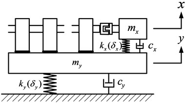
Taking raft frame as the research object, the excitation sources can be divided into two categories: the excitation sources with elastic connection to the raft frame and the excitation sources with rigid connection to raft frame. According to Newton’s second law, the vibration equation of the floating raft system is:
where and are the displacements of the unit with an elastic connection and the raft frame, respectively, and and are the excitation frequencies of the unit with an elastic connection and the unit with a rigid connection, respectively.
When 2, the vibration equation still represents multidisturbance vibration, and the equation can be simplified. Eq. (1) can be transformed into:
where , , , , , , , , , , and .
Using the multiscale method [26] and introducing a small perturbation parameter to perform a scale transformation of small items in the same equation:
Because the vibration displacement of a raft frame is much smaller than that of the unit, the perturbation is when performing scale transformation on the small terms and of Eq. (2b). The first-order excitation source corresponds to a low frequency, and the higher-order excitation source corresponds to a high frequency. Therefore, for the first-order vibration , the perturbation is , and for the higher-order vibration , the perturbation is .
Substituting Eq. (3) into Eq. (2) and retaining the terms containing and :
Next, the vibration situation under combined resonance was considered, i.e., the relationship between the following excitation frequencies was considered:
where and are adjustment parameters.
The solution of the equation can be written as follows:
where is the fast timescale and is the slow timescale.
Furthermore, differential operators can be defined as:
Substituting Eqs. (6) and (7) into Eq. (4), and comparing the coefficients of the same order on both sides of equation:
The general solution of Eq. (8) is:
where and are the functions of slow time ; and are the conjugate complex numbers of and ; , , and. and are the excitation source frequencies of units with an elastic connection.
Substituting Eq. (9) into Eq. (8b) and eliminating the secular terms:
Then, and can be written in polar form as:
where real numbers , , , and are the functions of slow time .
Substituting Eq. (11) into Eq. (10) and separating the real and imaginary parts:
where:
3. Nature of solution
In Eq. (12), let and to obtain a stable solution of vibration equation. Two scenarios exist, namely, the uncoupled state (, ) and coupled state (, ). For the uncoupled state, Eq. (12) can be reduced to:
Two scenarios also exist for the solution of Eq. (13): (a) Only one solution is available, and in this case, the system is stable; (b) The equation has three solutions, and in this case, the phenomena of saddle node bifurcation and jumping in the amplitude–frequency curve can occur. The number of solutions depends on the excitation intensity. When the equation has only one solution, the critical excitation amplitude is:
Eq. (14) shows that the critical excitation amplitude is related to both the damping and stiffness of system.
Eqs. (5), (9), and (11) can be combined to obtain the vibration displacements of unit with elastic connections and raft frame as follows:
Eq. (15) shows that in the coupled state, only one frequency exists when the raft frame () vibrates. In contrast, when the unit with an elastic connection vibrates, two additional frequencies ( and ) exist in addition to the frequency of its own excitation source. Among them, the vibration corresponding to frequency is caused by internal resonance. This vibration is absent in the uncoupled state.
When the floating raft system is in the uncoupled state, the stability of steady solution of raft frame vibration is the stability of autonomous system at the singular point . The system is forced to undergo a linear transformation.
By linearizing Eqs. (12c) and (12d) at the singular point , the autonomous differential equations for disturbances and can be obtained as:
By utilizing to eliminate in the above equation, the feature equation can be obtained as:
where and .
By expanding Eq. (17):
The solution of Eq. (18) is:
where and .
When and , is a real number and . In this case, the steady solution is unstable, i.e., the instability condition of steady solution is:
The boundary of unstable region can be determined using Eq. (20).
4. Analysis of numerical solution
4.1. Frequency response curve
The parameters of floating raft used in the simulation are shown in Table 1 [27, 28].
Table 1Parameters of floating raft system
Parameter (unit) | Value | Parameter (unit) | Value |
(kg) | 125 | (kg) | 3000 |
(N/m) | 4.4×10⁶ | (N/m) | 7.4×10⁶ |
(N/m) | 1.3×10⁵ | (N/m) | 2.2×10⁵ |
(Ns/m) | 1.5×10³ | (Ns/m) | 1.5×10⁴ |
(rad/s) | 315 | (rad/s) | 441 |
Eq. (14) determines the critical excitation with respect to the stability of raft frame vibration, i.e., 21 m/s2. When the excitation exceeds this value, the raft frame vibration is unstable.
When the excitation of unit with an elastic connection is , the excitation of unit with a rigid connection is less than the critical value , and vibration has only one solution branch. Therefore, the solution is stable. By sweeping the frequency upwards or downwards, the amplitude-frequency curves are consistent, as indicated by the black curve in Fig. 2. When the excitation exceeds the critical value, vibration has three solution branches. Among the solution branches, the intermediate branch is unstable, and the solutions in this branch will jump to the upper and lower solution branches. In addition, as the intensity of excitation increases, the frequency band corresponding to the intermediate solution branch expands, and the vibration displacement of raft frame also increases. When an upward frequency sweep is performed (i.e., the frequency increases), the solution of vibration moves to the right along the lower solution branch. Upon reaching the inflection point (the point where the lower solution branch intersects the intermediate solution branch), the solution suddenly jumps to the upper solution branch and smoothly moves to the right. When a downward frequency sweep is performed (i.e., the frequency decreases), the solution of vibration moves to the left along the upper solution branch. Upon reaching the inflection point (the point where the upper solution branch intersects the intermediate solution branch), it suddenly jumps down to the lower solution branch and then smoothly moves to the left. The jumping points of upward frequency sweep and downward frequency sweep are not at the same frequency, indicating that the amplitude-frequency curves of upward frequency sweep and downward frequency sweep are inconsistent. Thus, the vibration of unit with a rigid connection can destabilize the system.
Fig. 2Effect of varying excitation fy1 on raft frame vibration b
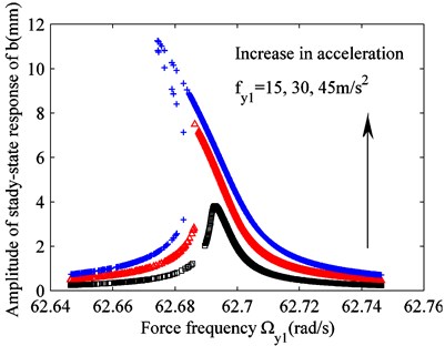
Fig. 3Effect of varying the excitation on raft frame vibration b
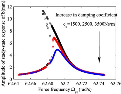
a) Variation in damping coefficient
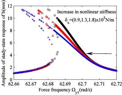
b) Variation in nonlinear stiffness
Although the elastic components of floating raft system are hard springs, the combined force of springs in the upper and lower layers provides the characteristics of a soft-spring vibration system; therefore, the skeleton curve of amplitude-frequency curve bends to the left. This suggests that although the soft spring is not actually applied, the hard spring vibration state (occurring at the unit with an elastic connection in the upper layer) and soft spring vibration state (occurring at the raft frame in the center) can simultaneously exist in the floating raft system.
When the excitations are 45 m/s2 and and the nonlinear stiffness and damping are 1.3×10⁵ N/m and 1.5×10³ Ns/m, respectively, the effects of damping and nonlinear stiffness on the raft frame vibration can be obtained, as shown in Figs. 3(a) and (b), respectively. Combining this result with Eq. (14), it can be concluded that the critical excitation required to cause system instability increases as the damping increases. Therefore, under the same excitation , the vibration displacement of raft frame decreases as the damping increases, and the system remains stable. Conversely, as the nonlinear stiffness increases, the amplitude of vibration displacement of raft frame remains unchanged. However, the frequency band corresponding to unstable solution increases, and the curvature of skeleton curve of the amplitude–frequency response also increases. Thus, the system becomes unstable. This shows that damping exerts the opposite effect on system stability compared to nonlinear stiffness.
Fig. 4Effect of varying excitation fx1(fx2) on raft frame vibration b
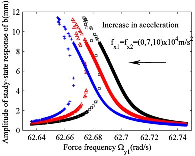
When the excitation, damping, and nonlinear stiffness of the unit with a rigid connection are 45 m/s2, 1.5×10³ Ns/m, and 1.3×10⁵ N/m, respectively, and the excitation of the unit with an elastic connection varies, the frequency response curve of raft frame vibration is similar to that shown in Fig. (4). Unlike the effects of damping and nonlinear stiffness on raft frame vibration, the increase in excitation shifts both the amplitude-frequency curve of raft frame and vibration skeleton curve to the left. The same effect can be obtained if the natural frequency of raft frame changes. Because the natural frequency of a system depends on the mass and rigidity of the system itself, application of an excitation to the unit with an elastic connection is equivalent to adding a virtual inertia to the raft frame to change its virtual natural frequency. This shows that the units on raft frame can serve as intermediate masses between each other to reduce the vibration of excitation source. Moreover, the vibration of each unit with an elastic connection can further increase the virtual mass of raft frame, making the system more stable. Because the excitation of elastic connection excitation source cannot be too large in practice, the vibration of elastically connected unit itself increases the vibration stability of floating system.
4.2. Unstable region of solution
When the nonlinear stiffness and damping are 1.3×10⁵ N/m and 1.5×10³ Ns/m, respectively, the effects of these parameters on the unstable region of solution can be determined, as shown in Fig. 5. The area of unstable region decreases as the damping increases. Nonlinear stiffness does not affect the area of unstable region of solution; however, the increased nonlinear stiffness shifts the unstable region downwards, as shown in Fig. 3, i.e., the intermediate solution branch falls into the unstable region.
Fig. 5Effect of varying stiffness and damping parameters on the unstable region of solution
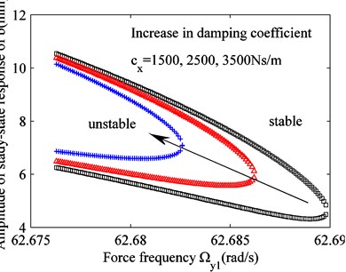
a) Variation in damping coefficient
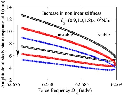
b) Variation in nonlinear stiffness
Fig. 6Effect of varying excitation fx1(fx2) on the unstable region of solution
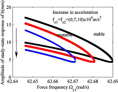
When the damping and nonlinear stiffness of the system are 1.5×10³ Ns/m and 1.3×10⁵ N/m, respectively, the unstable region of solution varies as the excitation of unit with an elastic connection changes, as shown in Fig. 6. The effect of excitation on the unstable region is more complex. As the excitation increases, the area of unstable region decreases. The same phenomenon was observed by system damping, and the region shifted downwards. The same phenomenon was observed by nonlinear stiffness. This further proves that the excitation of unit with an elastic connection has the same effect as an increase in the virtual mass of raft frame, increasing the vibration stability of floating raft system.
4.3. Changes in bifurcation solution
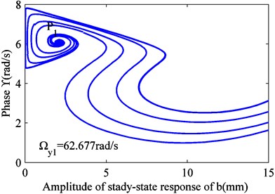
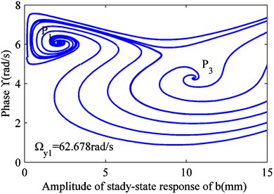
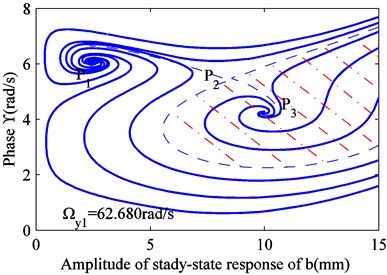
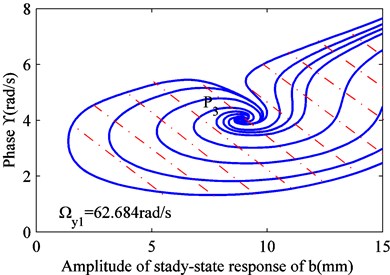
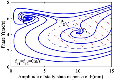
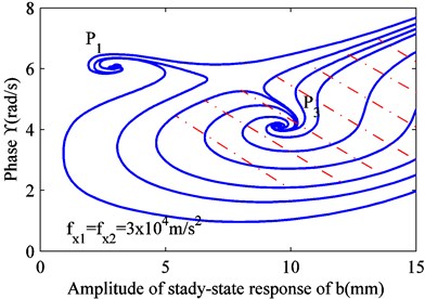
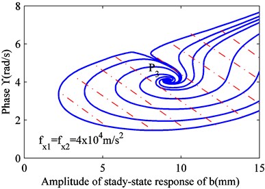
When is constant, Eq. (12) can be converted to a differential equation, and it can be solved. Thus, and can be obtained. Four values were selected for , as shown in Fig. 1. When the excitation frequency is less than the lower limit of frequency, all the solutions are attracted to the stable focus . As the excitation frequency increases, a new stable focus appears, and some solutions are drawn to it. As the excitation frequency increases, some solutions under certain initial conditions are pushed toward the critical state, passing through a newly formed saddle node . When this solution is affected by any perturbation, it is attracted to the stable focus or . The saddle node sits on the boundary between two stable focus areas. Under the initial conditions, the solutions in different regions are attracted to the corresponding focus.
Fig. 7Variation in the stability of solution at different excitation frequencies
a) 62.677 rad/s
b) 62.678 rad/s
c) 62.680 rad/s
d) 62.684 rad/s
Fig. 8Variation in stability of solution under different excitations fx1(fx2)
a) 0 m/s2
b) 3×10⁴ m/s2
c) 4×10⁴ m/s2
When the excitation frequency exceeds the upper limit of frequency, all the solutions are attracted to the stable focus . As the excitation frequency increases, the stable focus disappears, and the area corresponding to the stable focus increases. This also confirms that the intermediate solution branch of raft frame vibration is unstable, jumping upwards and downwards the two progressively more stable solution branches.
Under the condition that the excitation frequency 62.680 rad/s of unit with a rigid connection is constant, a variation in the excitation of elastic connection still changes the stability of vibration solution. By solving differential Eq. (12), the values of and can be obtained with different values for , as shown in Fig. 8. Fig. 8 shows that even if the excitation frequency is constant, an increase in excitation also shifts the vibration solution of raft frame to the stable focus , and stable focus gradually disappears. This shows that in addition to changing the excitation frequency, the excitation of unit with an elastic connection can also change the stability of vibration solution of raft frame. Thus, the excitation of unit with an elastic connection has a complex effect on the vibration of raft frame.
4.4. Raft frame vibration in coupled state
Factors affecting the vibration of a raft frame in the uncoupled state were discussed. Now, the coupling state is analyzed.
Fig. 9Effect of excitation fy1 on raft frame vibration
a) Jumping of vibration amplitude
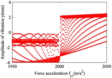
b) Magnified region of curve
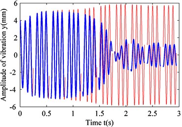
c) Time-domain graph
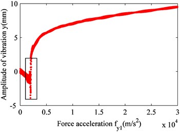
Fig. 9 shows that although the floating raft system does not exhibit double-cycle bifurcation in the coupled state, the amplitude of raft frame vibration abruptly changes when the excitation of unit with a rigid connection exceeds 2,000 m/s2. Before the abrupt change, the amplitude of raft frame vibration slowly increases with the increase in excitation intensity. Once the excitation intensity passes the point of abrupt change, the amplitude of raft frame vibration suddenly becomes positive and increases sharply, as shown in Fig. 9. In Fig. 9(c), when the excitation intensity is 1,990 m/s2 (blue curve), the vibration displacement is rapidly reduced after a certain period of adjustment. Then, the fluctuation increases up to a certain value and gradually stabilizes (i.e., the variation in vibration amplitude decreases). When the excitation intensity is 2,010 m/s2 (red curve), the amplitude of raft frame vibration slowly increases and gradually stabilizes without any fluctuation during the process. This phenomenon is similar to the effect of excitation of the unit with a rigid connection on the raft frame vibration in the uncoupled state. In other words, a critical value of excitation intensity exists at which the state of raft frame vibration changes.
5. Conclusions
In this study, the vibration characteristics of a floating raft system under multiexcitation condition were analyzed. The multiscale method was used to solve the equation for floating raft vibration under multiexcitation condition, and a stable region of the solution was determined. Factors affecting the vibration stability of raft frame were studied, in particular, the effects of different excitation sources. The conclusions are as follows:
1) Although the floating raft system does not use a soft spring, the location of raft frame within the intermediate layer results in vibration that fits the pattern of a soft spring, because of the combined force of hard springs in the upper and lower layers. The skeleton curve of amplitude-frequency response bends to the left.
2) A critical value of excitation exists for the unit with a rigid connection. Excitation intensities exceeding this threshold compromise the stability of raft frame vibration. The critical value depends on the damping and nonlinear stiffness of system. As the damping increases, the nonlinear stiffness decreases, the unstable frequency band narrows, and the raft frame vibration becomes more stable.
3) The excitation of unit with an elastic connection has the same effect as increasing the virtual mass of raft frame, increasing the stability of floating raft system.
In summary, to increase the vibration stability of a floating raft system, the units connected to raft frame should have elastic connections where possible.
References
-
Shahgholi M., Khadem S. E. Internal, combinational and sub-harmonic resonances of a nonlinear asymmetrical rotating shaft. Nonlinear Dynamics, Vol. 79, 2015, p. 173-184.
-
Murawski L., Charchalis A. Simplified method of torsional vibration calculation of marine power transmission system. Marine Structures, Vol. 39, 2014, p. 335-349.
-
Deng W., Zhang S., Zhao H., Yang X. A novel fault diagnosis method based on integrating empirical wavelet transform and fuzzy entropy for motor bearing. IEEE Access, Vol. 6, 2017, p. 35042-35056.
-
Deng W., Yao R., Zhao H., Yang X., Li G. A novel intelligent diagnosis method using optimal LS-SVM with improved PSO algorithm. Soft Computing, Vol. 23, Issue 7, 2019, p. 2445-2462.
-
Liu C. C., Jing X. J. Vibration energy harvesting with a nonlinear structure. Nonlinear Dynamics, Vol. 84, 2016, p. 2079-2098.
-
Pan B., Lu J., Shang F. L. Frequency analysis of nonlinear free vibration of a cross string. Nonlinear Dynamics, Vol. 72, 2013, p. 717-728.
-
Joo H. K., Sapsis T. P. Performance measures for single-degree-of-freedom energy harvesters under stochastic excitation. Journal of Sound and Vibration, Vol. 333, 2014, p. 4695-4710.
-
Ghasemloonia A., Rideout D. G., Butt S. D. Vibration analysis of a drillstring in vibration-assisted rotary drilling: finite element modeling with analytical validation. Journal of Energy Resources Technology, Vol. 135, 2013, p. 032902.
-
Askari H., Saadatnia Z., Esmailzadeh E., Younesian D. Multi-frequency excitation of stiffened triangular plates for large amplitude oscillations. Journal of Sound and Vibration, Vol. 333, 2014, p. 5817-5835.
-
Jiang X., Vakakis A. F. Dual mode vibration isolation based on non-linear mode localization. International Journal of Nonlinear Mechanics, Vol. 37, 2003, p. 837-850.
-
Xiao Z., Jing X., Cheng L. The transmissibility of vibration isolators with cubic nonlinear damping under both force and base excitations. Journal of Sound and Vibration, Vol. 332, 2013, p. 1335-1354.
-
Huang Q., Yan X., Wang Y., Zhang C., Jin Y. Numerical and experimental analysis of coupled transverse and longitudinal vibration of a marine propulsion shaft. Journal of Mechanical Science and Technology, Vol. 30, Issue 12, 2016, p. 5405-5412.
-
Huang Q., Yan X., Wang Y., Zhang C., Wang Z. Numerical modeling and experimental analysis on coupled torsional-longitudinal vibrations of a ship’s propeller shaft. Ocean Engineering, Vol. 136, 2017, p. 272-282.
-
Han H., Lee K., Jeon S. H., Park S. Lateral-torsional coupled vibration of a propulsion shaft with a diesel engine supported by a resilient mount. Journal of Mechanical Science and Technology, Vol. 31, Issue 8, 2017, p. 3727-3735.
-
Qinglei Z., Jianguo D., Suohuai Z., Yumin F. Nonlinear dynamic modeling for a diesel engine propeller shafting used in large marines. Chinese Journal of Mechanical Engineering, Vol. 27, Issue 5, 2014, p. 937-948.
-
Bellizzi S., Cote R., Pachebat M. Responses of a two degree-of-freedom system coupled to a nonlinear damper under multi-forcing frequencies. Journal of Sound and Vibration, Vol. 332, 2013, p. 1639-1653.
-
Grilli R., Krishnan R., Hu W., Wereley N. M., Sieg T. Mechanisms-based analysis of filled elastomeric dampers under single and dual frequency excitations. Journal of the American Helicopter Society, Vol. 7, 2008, p. 252-267.
-
Bakri T., Nabergoj R., Tondl A. Multi-frequency oscillations in self-excited systems. Nonlinear Dynamics, Vol. 48, 2007, p. 115-127.
-
Facci A. L., Porfiri M. Nonlinear hydrodynamic damping of sharp-edged cantilevers in viscous fluids undergoing multi-harmonic base excitation. Journal of Applied Physics, Vol. 112, 2012, p. 124908.
-
Eissa M., Kamel M., El Sayed A. Vibration reduction of a nonlinear spring pendulum under multi external and parametric excitations via a longitudinal absorber. Meccanica, Vol. 46, 2011, p. 325-340.
-
El Sayed A.-T., Kamel M., Eissa M. Vibration reduction of a pitch-roll ship model with longitudinal and transverse absorbers under multi excitations. Mathematical and Computer Modelling, Vol. 52, 2010, p. 1877-1898.
-
Kamel M., Eissa M., El Sayed A.-T. Vibration reduction of a nonlinear spring pendulum under multi-parametric excitations via a longitudinal absorber. Physica Scripta, Vol. 80, 2009, p. 1-13.
-
Thomsen J. J. Effective properties of mechanical systems under high-frequency excitation at multiple frequencies. Journal of Sound and Vibration, Vol. 311, 2008, p. 1249-1270.
-
Guo J., Zhang W., Zhang X. Modeling and analysis of the transient vibration of camshaft inmulti-cylinder diesel engine. Advances in Mechanical Engineering, Vol. 7, Issue 11, 2015.
-
MIL-STD-740-2. Structure-borne vibratory acceleration measurements and acceptance criteria of shipboard equipment. Washington DC, Department of Defense, 1986.
-
Yaman M. Analysis of subcombination internal resonances in a non-linear cantilever beam of varying orientation with tip mass. International Journal of Non-Linear Mechanics, Vol. 58, 2014, p. 22-29.
-
Tao Z. Research on Vibration Isolation Characteristic and Active Control of Floating Raft. Nanjing University of Aeronautics and Astronautics, 2012.
-
Chen Y. Active Vibration Control of Marine Floating Raft Vibration Isolation System. Dalian Maritime University, 2012.
