Abstract
A considerable amount is being invested by the vehicle developers in reducing the power needed for propulsion. The vehicle is optimized such to reduce the aerodynamic drag as the drag force is the leading resistance to the motion of vehicle. The flow separation at the rear end of the vehicle is one of the major causes of this drag. This paper investigates the effect of the delta shaped aerodynamic devices, known as vortex generators, installed at the roof of a hatchback type car to delay the flow separation. Mostly vortex generators are used in aircrafts and faster road vehicles with a notch at rear like the sedans. This experiment, unlike the previous researches, investigates and compares the aerodynamic drag and lift of the hatch back vehicle with and without Vortex Generator. Here it is represented that the improvement in aerodynamic drag force reduction, although of very minimal amount, can be achieved by using VGs on hatch back type cars.
1. Introduction
In today’s society, it has been determined by the energy analysts that the fuel consumption is increasing at alarming rate. Since energy is not a finite service, there have to be certain movements taken to improve the fuel economy in automobiles [1]. Improvement in the aerodynamics of the vehicle is one of the key concerns of the vehicle developers to advance the fuel economy [1, 2]. Aerodynamics helps to decrease the drag force, makes cars more stabilized and gives a chance of reducing fuel consumption. Pressure drag is the pressure differences in front and rear end of the vehicle, and as the ground vehicles are concerned, pressure drag contributes almost 90 % of the total drag [4]. It has been researched and found that there is 40 % of the overall drag force which is concentrated only at the rear of the vehicle [5]. The flow separation which takes place at the rear end of the vehicle is one of the key causes of aerodynamic drag [1, 3]. Many researchers have been researching on methods of the flow control over the vehicle. The methods found out are basically divided into two sections: active and passive flow controls. Active methods include modification in shape of the structure, steady blowing, suction and air jet, on the other hand passive methods comprise of adding some aerodynamic devices for e.g. spoiler, vortex generators, splitters etc. [5]. Because there is so much to adjust in a small vehicle including the passengers as well as their luggage, it is not very easy to have an aerodynamically ideal body shape. So, vortex generators are used over the bluff-like body of the cars. The effect of vortex generators on the hatchback type cars is been reviewed in this paper. Vortex generators are aerodynamic surfaces creating vortices in the medium [6, 7]. According to the researches and investigations it is concluded that the vortex generators modifies the inner structure of the boundary layer, making it more resistant to the separation [6], hence preventing the flow separation at the rear and also lowering the aero-acoustic noise [8], where it is installed. Mostly VGs are used in sedan type cars rather in hatchback type car because drag coefficient and lift coefficient for the hatchback design is much lower than the sedan design [9]. But this paper investigates the effect of VGs on hatchback type cars that how much drag and lift coefficients are varied after the installation of the VGs. Using VGs and spoilers on a car body are passive methods for reduction in drag force in fast moving cars. Our study is about passive means to improve the aerodynamics of hatchback type cars which already is one of the less researched fields since mostly these passive means for reduction of drag is usually used in fast sedan class cars. A passenger car is considered as a bluff body and generally coefficient of drag is between 0.2 and 0.5, and is greater than 1.0 [3, 10].
2. Mechanism of Vortex generators
Vortex Generators are the aerodynamic passive devices which can be categorized as boundary layer manipulators [6, 8]. The function of a VG is to energize an opposing pressure gradient boundary layer and enhance its mixing which is about to separate, by conveying high momentum fluid from the outer part of the boundary layer down to the low momentum zone closer to the wall [6, 11-13].
The height of the car decreases at the end and therefore increasing the flow area which ultimately decreases the velocity of flow as the air expands at the rear. This reduction in velocity causes increment in the pressure, hence increasing the reverse flow at the rear [10, 14].
As the downstream pressure increases at the point ‘C’ in Fig. 1, it creates a reverse flow opposing the main flow and creating drag. At point ‘A’, which is the upstream, there is no opposing flow because the momentum of the present boundary layer overcomes the pressure gradient. The point ‘B’ represents the balance between the momentum and the pressure gradient of the boundary layers.
Basically, vortex generators trail on the principle of exchange of momentum between the upstream and downstream flow. So, when it is installed it balances the pressure gradient between the upstream and downstream, eventually preventing the opposing forces [15]. The vortex generators are installed just before the separation point at the rear. They produce small vortices there, to shift the separation point a little further which allows the expanded air-flow to continue for some longer and hence decreasing the velocity with an increment in the static pressure at the rear. This increment of static pressure results in drag reduction by increasing the back pressure, following twin benefits: narrowing the separation region as well as raising the flow pressure at the separation [10, 14]. Though the vortex generators themselves increase the drag by creating small vortices in the flow, but still are used for vehicles because the amount of drag created by them is of negligible amount in comparison to the drag created by the vehicle’s structure. The overall effect of VGs can be calculated by totaling both the positive and negative effects of the VG on the vehicle [3]. Effect of delaying the flow separation and the amount of the drag by the VG itself is directly proportional to the size of the vortex generators. As the size of the VG increases it enhances the virtue of effectively delaying the flow separation but also increasing drag by its own structure. So, there must be some optimum height above which the increment does not work in a positive way. The optimum size of the VG is discussed further in the design section.
Fig. 1Depiction of velocity profile at the rear Source: [10, 14]
![Depiction of velocity profile at the rear Source: [10, 14]](https://static-01.extrica.com/articles/20399/20399-img1.jpg)
Fig. 2Depiction of flow around VG Source: [10, 14]
![Depiction of flow around VG Source: [10, 14]](https://static-01.extrica.com/articles/20399/20399-img2.jpg)
3. Designing of the Vortex generators
The models of vortex generators are based on the theory adding the lift force induced by the vortex generator to the system of Navier Stokes equations. This lifting force spins the flow giving rise to the formation of vortices. In the model the lift force is estimated from the Prandtl lifting theory [16].
Fig. 3A vortex generator reduces the boundary layer height and reduces boundary layer separation
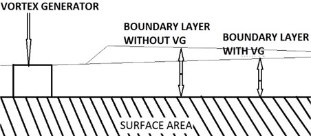
According to many researches the optimum height of the Vortex generators are defined almost equal to the boundary layer thickness [1-3, 6-11, 13-15].
30 mm is the boundary layer thickness at the roof end right away in front of the flow separation point [1]. Therefore, the most favorable height for the VG is found to be up to roughly 30 mm. A bump-shaped piece with a rear slope angle of 25 to 30° is found to be most suitable shape of the VG.
The location of Vortex Generators is selected at a point immediately upstream of the flow separation point and a point at a distance of 100 mm in facade of the roof end as shown in Fig. 4.
To minimize the drag it is important to design the bump-shaped VG smoothly curved at the front half contour and to cut the rear half in a straight line to an approximate angle of 27°. It is also to maximize the generation of a stream wise vortex.
On the other hand, the delta-wing-shaped VGs are installed at a yaw angle of 15° to the direction of airflow.
With help of oil flow measurement, the direction of the airflow was found to be different between sideways positions on the roof. The direction of airflow aligns with backward direction at the center of the car, this airflow starts deviating towards the center as the point of measurement shifts away from the central position. This is the reason why the delta-wing-shaped VGs must be installed at an angle of 15° alongside the vehicle centerline for the central position, while they must be installed at an angle near 0° for positions away from the center. The VGs which are delta wing- shaped VGs, according to the previous researches, were found out as less sensitive to vary in height than bump-shaped VGs. According to previous researches conducted it is concluded that the drag reduction effects for the VGs of different heights are almost the same.
Fig. 4Position of VGs
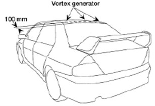
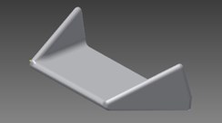
Fig. 5Solid model of VG in Autodesk Inventor
4. Geometry preparation of the car model
Modelling of the HYUNDAI i30 hatchback type car is done using Autodesk Inventor Professional 2013. The solid model of the car is made using 3 view method and extrusion with the help of following 3D surface model of the car.
Fig. 6Solid model of hatchback type car
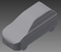
Fig. 7Installation of VGs on the solid model
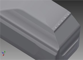
5. Result and discussion
Autodesk Flow Design is general purpose preprocessor for simple CFD analysis, which is used here for the CFD investigation of the hatchback type car with and without vortex generator. The basic model and the model with VGs, which are created using Autodesk Inventor, are analyzed for flow variation and coefficient of drag at different wind speeds ranging from 5 m/s to 50 m/s. velocity as well as pressure contours are plotted against different wind speeds for both the models: with VG and without VG respectively.
Figs. 8-11 shows flow over model with VG at different speeds. Figs. 12-15 shows flow over model without VG at different speeds.
Fig. 8Wind speed: 5 m/s
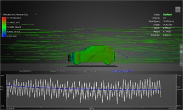
Fig. 9Wind speed: 10 m/s
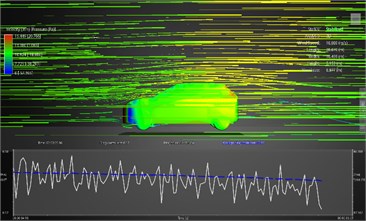
Fig. 10Wind speed: 20 m/s
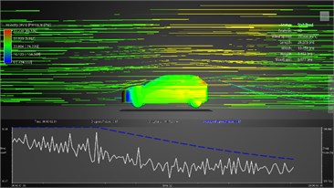
Fig. 11Wind speed: 30 m/s
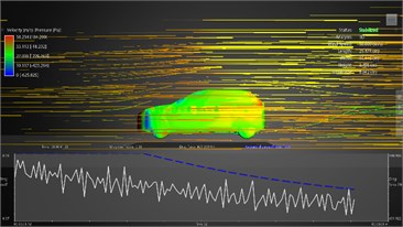
Fig. 12Wind speed: 5 m/s
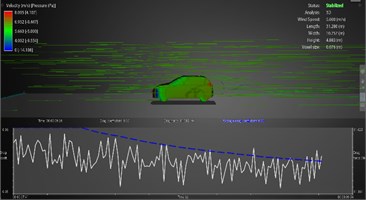
Fig. 13Wind speed: 10 m/s
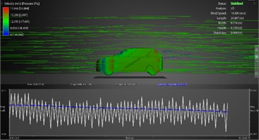
Fig. 14Wind speed: 20 m/s
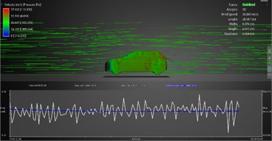
Fig. 15Wind speed: 30 m/s
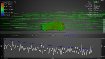
The enhanced performance of the hatch back type car with vortex generator was determined and the comparison was made between cars with and without vortex generators. By adding the vortex generators at the rear end of the car gave an average reduction of drag by very minimal amount when compared to the model without Vortex Generators. This development is focused on the enhancement of the performance of hatch back types cars using vortex generators and the comparison results that the vortex generator gave the better performance on hatchback types cars.
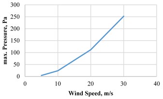
Figs. 16-18 shows different graphs for model with VG, and Figs. 19-21 shows different graphs for model without VG.
Fig. 16Drag coefficient vs wind speed
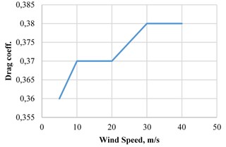
Fig. 17Drag coefficient vs wind speed
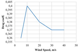
Fig. 18Maximum velocity vs wind speed
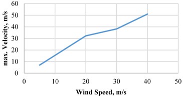
Fig. 19Maximum velocity vs wind speed
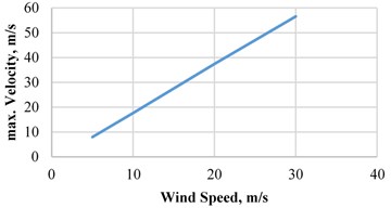
Fig. 20Maximum pressure vs wind speed
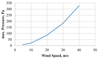
Fig. 21Maximum pressure vs wind speed
6. Conclusions
The conclusions of the study are summarized as follows:
1) To reduce aerodynamic drag the Vortex Generators should be installed at roof, above the rear wind shield, just before the flow separation at the upstream on the hatch back types car. It delays the flow separation at the rear end of the car.
2) The optimum height of the vortex generator is almost equal to the boundary layer i.e. 15 to 25 mm.
3) Considering all the results and graphs the aerodynamic drag is reduced by installing the vortex generators on the hatch back type cars, but with a minimal amount. So, it is concluded that the vortex generators are not very effective in case of hatch back type cars.
References
-
Dheeraj Sagar, Akshoy Ranjan Paul, Ravi Ranjan Upadhyay, Anuj Jain Aerodynamic effects of rear spoiler and Vortex generators on passenger cars. International Conference on Theoretical, Applied, Computational and Experimental Mechanics, 2010.
-
Ram Bansal, R. B. Sharma Drag reduction of a generic passenger car using Vortex generator with different yaw angles. International Journal of Automobile Engineering Research and Development, Vol. 3, Issue 2, 2013, p. 73-80.
-
Md. Hasan Ali, Mohammad Mashud, Abdullah Al Bari and Muhammad Misbah-Ul Islam Aerodynamic drag reduction of a car by vortex generation. International Journal of Mechanical Engineering, Vol. 2, Issue 1, 2013, p. 12-21.
-
Adarsh P., Andrew George Cherian, Arun K. S., D. Roshan Kumar Numerical investigation of drag on a trailing aerodynamic sedan vehicle. International Journal of Mechanical and Production Engineering (IJMPE), Vol. 2, Issue 4, 2014, p. 81-86.
-
Mohd Nizam Sudin, Mohd Azman Abdullah, Shamsul Anuar Shamsuddin, Faiz Redza Ramli, Musthafah Mohd Tahir Review of research on vehicles aerodynamic drag reduction methods. International Journal of Mechanical and Mechatronics Engineering IJMME-IJENS, Vol. 14, Issue 2, 2014, p. 35-47.
-
Gopal P., Senthil Kumar T. Aerodynamic drag reduction in a passenger vehicle using Vortex generator with varying yaw angles. ARPN Journal of Engineering and Applied Sciences, Vol. 7, Issue 9, 2012, p. 1180-1186.
-
Johari Bin Ismail Design and Analysis of Vortex Generator for a HEV Model. Bachelor Thesis, University of Malaysia, 2008.
-
Xue Sidney, Johnson Bradley, Chao David, Sareen Ashish, WestergaardCarsten Advanced aerodynamic modeling of Vortex generators for wind turbine applications. European Wind Energy Conference (EWEC), Warsaw, Poland, 2010.
-
Mohd Khalil Azingah Bin Salleh Simulation and Analysis Drag and Lift Coefficient between Sedan and Hatchback Car. Bachelor Thesis, University of Malaysia, 2009.
-
Mohan Jagadeesh Kumar M., Anoop Dubey, Shashank Chheniya, Amar Jadhav Effect of Vortex generators on aerodynamics of a car: CFD analysis. International Journal of Innovations in Engineering and Technology (IJIET), Vol. 2, Issue 1, 2013, p. 137-144.
-
Fernández U., Clara Velte M., Réthoré P.-E., Sørensen N. N. Self-similarity and helical symmetry in Vortex generator flow simulations. Journal of Physics: Conference Series, Vol. 555, 2014, p. 012036.
-
Lu Ping, Liu Chaoqun Numerical study on mechanism of small Vortex generation in boundary layer transition. 49th AIAA Aerospace Sciences Meeting including the New Horizons Forum and Aerospace Exposition, 2011.
-
Quackenbush Todd R., Danilov Pavel V., Whitehouse Glen R. Flow driven oscillating Vortex generators for control of boundary layer separation. 40th Fluid Dynamics Conference and Exhibit, Fluid Dynamics and Co-located Conferences, 2010.
-
Sujith Sai K., Reddy Ravindra G. CFD analysis of sedan car with Vortex generators. International Journal of Mechanical Engineering Applications Research – IJMEAR, Vol. 3, Issue 3, 2012, p. 179-184.
-
Ahmed Haseeb, Chacko Sibi Computational optimization of vehicle aerodynamics. Annals of DAAAM for 2012 and Proceedings of the 23rd International DAAAM Symposium, Vol. 23, Issue 1, 2012, p. 313-318.
-
Jirasek Adam A Modified Vortex Generator Model and its Application to Complex Aerodynamic Flows. Division of Aeronautics, FFA, FOI – Swedish Defence Research Agency, 2004.
