Abstract
With the rapid development of railway construction, many railway projects have crossed the soft soil deposit. In order to obtain ground settlement data after train operation to ensure the safety of railway, the train-track dynamic model and track-ground finite element model were established to predict accumulated deformation of soft soil foundation induced by dynamic train load. Compared to the measured vibration acceleration on the sleeper and ground, the predicted vibration acceleration can match well with the measured vibration acceleration across the full range of time history shown. The results showed that after many times of train operations, the cumulative deformations of the ground at different depth are quite different, it may affect the safety of the railway operation, the foundation reinforcement measures can be considered during construction.
1. Introduction
With the rapid development of railway construction, many railway projects have crossed the soft soil deposit. The original survey design specifications and related manuals cannot meet the requirements of the design standards for the evaluation and treatment of the soft soil deposit. The settlement of the ground surface, especially when it occurs in a rapid and differential manner, may cause severe damage on human-built structures and the loss of human lives.
Recently, some scholars studied train induced ground vibration and settlement through measurement, numerical simulation, and empirical equation [1, 2]. Shih et al. [3] built a finite element model of the track and ground to study train induced soft ground deflections. Wu et al. [4] used real-time strong-motion observation tests in a permafrost region along Qinghai-Tibet Railway to study displacement response of embankment. Cui et al. [5] based on numerical analyses for the actual tunnel excavation to examine the settlements of ground surface. Therefore, the research on ground deformation monitoring over soft soil deposit has undoubtedly played an important guiding role in railway design.
In order to obtain ground settlement data after train operation to ensure the safety of railway, the train-track dynamic model and track-ground finite element model were established to predict accumulated deformation of soft soil foundation induced by dynamic train load. The results can evaluate the safety of the railway operation.
2. Method
In order to analyze the dynamic deformation mechanism caused by moving train loads, this section establishes the of train-track coupling dynamic model, fully considering the influence of track irregularity, and calculating the wheel-rail interaction when the train runs on the track structure in the time domain. On this basis, the finite element model of track structure and ground is built and excitation by moving train loads, and the dynamic response characteristics of the ground under moving load are obtained, and the long-term accumulated deformation of ground induced by dynamic train loads is predicted.
2.1. Train-track dynamic model
The axial load of the train passing through the uneven track including static load and dynamic load. The static load is generated by the self-weight of the train, and the dynamic load is formed by the contact of the wheel and rail when the train is running. In order to calculate the dynamic response between the train and the track, a train-track interaction dynamic model is established, which takes into account the interaction between the train vehicle, the rails, the underlying underlay and the fasteners, sleepers, track beds and foundations. It includes the vehicle submodel and the track structure submodel, as shown in Fig. 1.
Fig. 1Train-track dynamic model
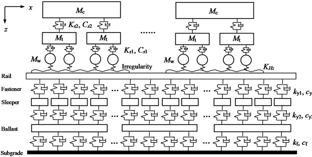
A train consists of eight cars, each of which includes 10 degrees of freedom. The train is simulated to run on the track at a constant speed, and the relative displacement between the trains can be ignored. According to the Lagrange equation of motion, the dynamic equilibrium equation of the train model can be established as Eq. (1):
where [M]c, [K]c and [C]c are mass matrix, stiffness matrix and damping matrix of train, respectively. {¨q}c, {˙q}c and {q}c are acceleration, velocity and displacement vector of train. {F}c is the wheel and track interaction force [6]. The train dynamic parameters are shown in Table 1.
Table 1Train dynamic parameters
Distance between two bogies | 18.0 m | Wheelset mass | 1900 kg |
Distance between two axles of bogie | 2.4 m | Wheel rolling radius | 0.4575 m |
Car mass | 29600 kg | Primary suspension stiffness | 8.37×10⁵ kN/m |
Car body inertia | 2.319×10⁶ kg∙m2 | Secondary suspension stiffness | 4.1×10⁵ kN/m |
Bogie mass | 1700 kg | Primary suspension damping | 3 ×10⁵ kN∙s/m |
Bogie inertia | 1700 kg∙m2 | Secondary suspension damping | 1.087 ×10⁵ kN∙s/m |
The entire track structure system simulation is based on the finite element method and is set up as a three-layer structure model including rails, sleepers, ballast and subgrade, as shown in Fig. 1. The degree of freedom of the track system is set on the same plane as the degree of freedom of the vehicle system. In order to reduce the size of the finite element stiffness matrix, the steel rail is assumed to be a discrete finite length Euler beam, ignoring the influence of shear force and moment of inertia, and an adjacent analysis unit is formed by the adjacent two sleepers and ballast supporting the rail, as shown in Fig. 2. The track structure dynamic parameters are shown in Table 2.
Based on the Hamilton principle, the dynamic equation of the orbit model is as follows:
where [M]1, [K]1 and [C]1 are mass matrix, stiffness matrix and damping matrix of track structure, respectively. {¨q}1, {˙q}1 and {q}1 are acceleration, velocity and displacement vector of track structure. {F}1 is the wheel and track interaction force [6].
Fig. 2Track structure unit
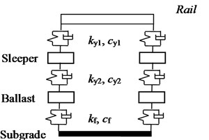
Table 2Track structure parameters
Rail elastic modulus | N/m2 | 2.06×10¹¹ | Rail mass | kg/m | 60.64 |
Rail cross-sectional area | m2 | 7.745×10⁻³ | Rail section moment of inertia | m4 | 3.217×10⁻⁵ |
Rail density | kg/m3 | 7830 | Rail elastic pad damping | N∙s/m | 5×10⁴ |
Rail elastic pad stiffness | MN/m | 100 | Sleeper mass | kg | 251 |
Sleeper spacing | m | 0.6 | Ballast elastic modulus | Pa | 0.8×10⁸ |
Ballast mass | kg | 630 | Subgrade elastic modulus | Pa/m | 1.3×10⁸ |
Ballast damping | N∙s/m | 1.6×10⁵ | Subgrade damping | N∙s/m | 6.32×10⁴ |
The wheel-rail contact force acts on the wheel-rail contact point, and the forces acting on the wheel pair and the rail are equal in magnitude and opposite in direction. The wheel-rail contact force expression is as follows:
where F0 is train static load. qwi and qri are vertical displacement of the wheel at the wheel-rail contact and the vertical displacement of the track, respectively. h represents the irregularity of the track surface at the wheel-rail contact.
Track irregularity is the main reason of dynamic response caused by train operation, and it is the excitation source of wheel-rail system. Considering that the established train-track dynamic model only considers the vertical dynamic response, the track irregularity is based on the spectrum used by Lombaert [7]. The simulation is as follows:
where k1,0= 1 rad/s, S(k1,0)=1×10⁻⁸ m3, w= 3.5.
2.2. Track-ground finite element model
The track-ground model was based on finite element to build. The track structure model consists of rails, sleepers, ballasts. The track adopts 60 kg/m, U75V hot-rolled steel rail, and the distance between two rails is 1.435 m. The relevant physical property parameters are shown in Table 3.
Table 3Physical and mechanical parameters of track structure finite element model
Model | Elastic modulus (MPa) | Poisson’s ratio | Density (kg/m3) |
Rail | 210000 | 0.25 | 7850 |
Sleeper | 30000 | 0.2 | 2400 |
Ballast | 300 | 0.35 | 1800 |
For the ground model, according to the detailed geological investigation, the physical and mechanical parameters of the main soil layers are shown in the table below.
Table 4Physical and mechanical parameters of ground model
Soil layer | Thickness (m) | Density (g/cm3) | Elasticity modulus (MPa) | Poisson’s ratio ν | Vp (m/s) | Vs(m/s) |
Artificial fill | 2 | 1.85 | 200 | 0.30 | 390.5 | 210.0 |
Mucky soil | 8 | 1.83 | 180 | 0.32 | 374.6 | 180.4 |
Fine sand | 2.5 | 1.87 | 250 | 0.25 | 412.1 | 254.3 |
Medium-coarse sand | 15 | 1.90 | 300 | 0.25 | 435.1 | 262.3 |
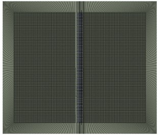
For the train load, this paper simulates moving train loads by applying wheel-rail contact force which obtain from train-track dynamic model to the rail surface. The train speed is 20 km/h. For the boundary condition, by coupling the finite element and the infinite element to simulate infinite ground. It has wide applicability in the problem of simulating the infinite domain without losing the accuracy of calculation. The track-ground model is shown in Fig. 3.
Fig. 3Track-ground finite element model
2.3. Accumulated deformation of soft soil foundation induced by dynamic train load
The cumulative deformation of the ground under the moving train dynamic load can be calculated based on the empirical formula which proposed by Chai and Miura [8]. The formula was established by the soil cumulative plastic strain results based on the indoor dynamic triaxial test, which is defined as:
where εp is the cumulative plastic strain, N is the number of cyclic loadings, qd is the dynamic deviatoric stress, qs is the initial static deviatoric stress, and qf is the static strength of the soil. When the soil is undrained, qf=2Cu, Cu can be obtained by shear test.
The specific analysis process is: a) dynamic analysis of the three-dimensional track-ground finite element model. The dynamic moving load is the wheel-rail contact force obtained by the train-track dynamic model. b) The dynamic analysis is carried out to obtain the dynamic response of the soil after one single train pass-by. The maximum dynamic deviator stress qd of the soil can be obtained. c) The static analysis of the model can obtain the initial static deviator stress qs of the soil. d) Use the empirical formula Eq. (5) to calculate the plastic cumulative strain of the ground under any vehicle load times, and calculate the cumulative deformation of the ground.
3. Results
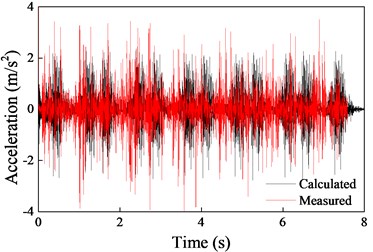
In order to verify the validity of the models, the calculated vibration accelerations on the sleeper and ground (10 m from the track) were compared with the measurement data, as shown in Fig. 4. Predicted vibration acceleration for both on the sleeper and ground compare well the measured vibration acceleration across the full range of time history shown.
Fig. 4Comparison of measured and predicted acceleration
a) On the sleeper
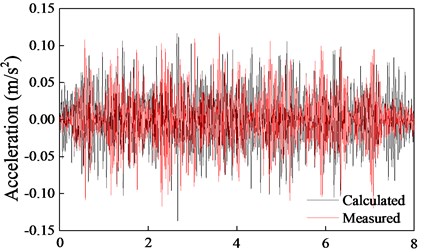
b) 10 m away from the track on the ground
Fig. 5Ground settlement changed with different train pass-by numbers
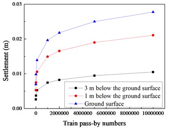
The cumulative plasticity in the soil is larger in the surrounding area of the train operation and is smaller away from the train running area. In the soil below the train running, the cumulative plastic strain is the largest. The integral deformation of the soil can be obtained by integrating the plastic strain in the depth direction. It can be seen from Fig. 5 that the cumulative deformation of the ground increases with the increase of the number of times of loading. The deformation rate is the largest in the early stage of loading, and as the number of loads increases, the growth rate of cumulative deformation gradually decreases, and 500,000 times is the inflection point of the curve. Before 500,000 times of train operations, the cumulative deformations of the soil at the ground surface, 1 m under the ground surface and 3 m under the ground surface are close, and when the number of loading increases to 10,000,000 times and 20,000,000 times, the cumulative deformations of the ground at different depth are quite different. It may affect the safety of the railway operation, the foundation reinforcement measures can be considered during construction.
4. Conclusions
The train-track coupling dynamic model and track-ground finite element model were stablished to predicted accumulated deformation of soft soil ground induced by dynamic train load. The conclusions can be drawn as below:
1) Compared to the measured vibration acceleration on the sleeper and ground, the predicted vibration acceleration can match well with the measured vibration acceleration across the full range of time history shown.
2) Train operations may affect the safety of the railway operation, the foundation reinforcement measures can be considered during construction.
References
-
Pakbaz M. S., Imanzadeh S., Bagherinia K. H. Characteristics of diaphragm wall lateral deformations and ground surface settlements: case study in Iran-Ahwaz metro. Tunnelling and Underground Space Technology, Vol. 35, 2013, p. 109-121.
-
Wang F., Gou B., Qin Y. Modeling tunneling-induced ground surface settlement development using a wavelet smooth relevance vector machine. Computers and Geotechnics, Vol. 54, 2013, p. 125-132.
-
Shih J. Y., Thompson D. J., Zervos A. The influence of soil nonlinear properties on the track/ground vibration induced by trains running on soft ground. Transportation Geotechnics, Vol. 11, 2017, p. 1-16.
-
Wu Z., Chen T., Zhao T., Wang L. Dynamic response analysis of railway embankments under train loads in permafrost regions of the Qinghai-Tibet Plateau. Soil Dynamics and Earthquake Engineering, Vol. 112, 2018, p. 1-7.
-
Cui Y., Kishida K., Kimura M. Prevention of the ground subsidence by using the foot reinforcement side pile during the shallow overburden tunnel excavation in unconsolidated ground. Tunnelling and Underground Space Technology, Vol. 63, 2017, p. 194-204.
-
Zhang J., Gao Q., Tan S. J., Zhong W. X. A precise integration method for solving coupled vehicle-track dynamics with nonlinear wheel-rail contact. Journal of Sound and Vibration, Vol. 331, Issue 21, 2012, p. 4763-4773.
-
Lombaert G., Degrande G. Ground-borne vibration due to static and dynamic axle loads of InterCity and high-speed trains. Journal of Sound and Vibration, Vol. 319, Issue 3, 2009, p. 1036-1066.

