Abstract
The paper presents extended abstract on research on rail vibration caused by passing train. The purpose of the investigation was analysis of information capacity of vibration signal in case of different types of railway vehicles. The research was conducted on real rail track with regular operational environment. The measurement system consisted of three 3-axial vibration acceleration sensors and a data-acquisition device registering continuous waveforms of signals. The result analysis present shapes of the signals for separate periods and as comparison for different rail vehicles.
1. Introduction
There are many of publication in scope on research on railway vibration but most of them are focused on ground vibration induced by passing trains [1-3]. The ground vibration induced by moving trains is a complicated dynamic problem. Various sorts of vibration can be generated by the passage of trains due to many sub-sources, as irregularities of rail and wheel, defects, train suspension properties, sleepers constructions etc. Vibrations are transmitted through the track structure and soil medium [4]. For the purpose of this research one vibration generation has been considered. The excitation caused by the regular repetitive action of moving wheel loads on the rail and impact caused by the rotating wheels over the rails due to surface irregularities [4].
The authors conducted many researches on railway vibration, takin into consideration different source of vibration as railway infrastructure elements or operations and propagation properties [5-7]. This paper presents research on rail vibration caused by passing train. The purpose of the investigation was analysis of information capacity of vibration signal in case of different types of railway vehicles. The assumption of investigation was that there are possibilities of selection of parts of the signals carried information on passing train vehicle.
2. Research method
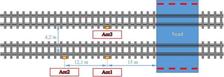
The research was conducted on real rail track with regular operational environment. The measurement system was developed with assumption of non-interfere into working properties of the rail traffic control system and track construction not to influence on transport safety. Thus, it was in situ experiment. The research involved a laboratory measuring system consisting of Dytran and PCB sensors together with the Sony SIR 1000i recorder (Fig. 1). During this study, accelerometer A and B were placed at a distance of 15.0 [m] from the edge of the concrete slab of road and rail crossing. Accelerometer C was placed at a distance of 12.1 from the accelerometer group A and B (27.1 m in total from the edge of the concrete slab). All sensors were 3-axial accelerometers. The sensor arrangement scheme is shown in the Figure 2.
During the research numerous train passages have been recorded. The measurement result are collection of multi-sample volume data selected due to the train vehicles.
Fig. 1Measurement system
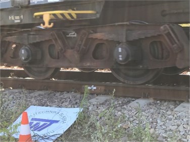
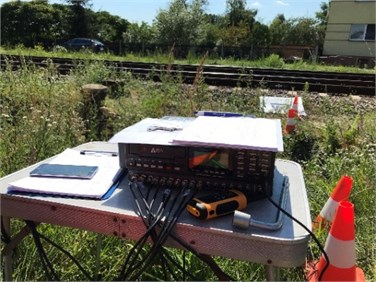
Fig. 2The sensor arrangement scheme
3. Result
The paper presents selected results of vibration generated by the passage of trains. The figures are taken from the monitoring software and it should be considered as overview of the registered signals.
Fig. 3Waveform of 3-axial vibrations of passing each other locomotive ST44 and ETU ElfII
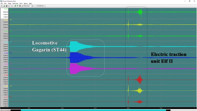
The figure 3 presents 3-axial vibrations signals of passing each other locomotive Gagarin ST44 and electric traction unit ElfII. The trains were driven on opposite tracks. The ST44 were recorded by sensor Acc3 (Fig. 2) and Elf II by sensors Acc1 and Acc2 (Fig. 2). These trains are completely different construction and the shapes of vibration signals are also different.
Figures 4 and 5 present vertical vibration of cargo train recorded on sensors Acc1 and Acc2 attached at a distance of 12.1 m.
Fig. 4Vertical vibration of cargo train, sensors Acc1 and Acc2
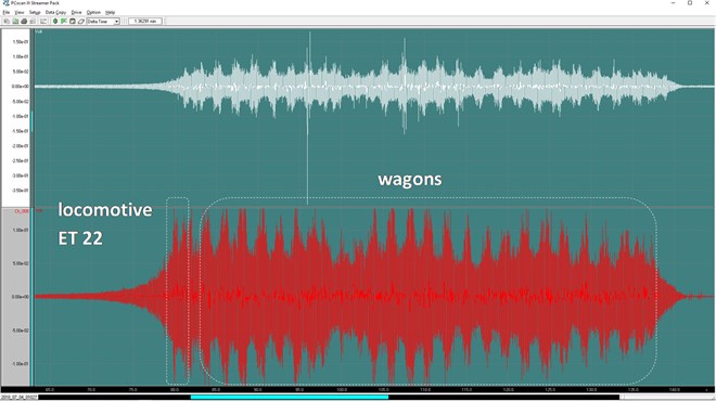
Fig. 5Zoom of vibration signal of cargo train – selection of signal periods
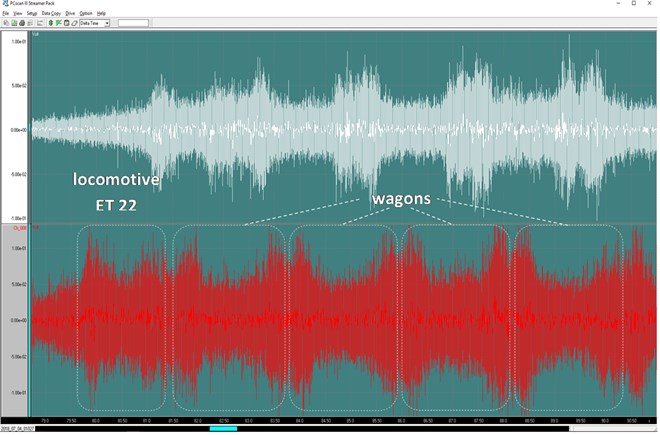
Based on the preliminary analysis of shape of the signal (Fig. 5) it can be separated segments of the signal corresponded with locomotive induced vibration and wagon induced vibration.
4. Conclusions
The paper presents results of preliminary research on rail vibration of passing trains. The analysis was conducted for purpose of evaluation of information carried in recorded signals. First conclusions are that shapes of the vibration signals are different for different type of train vehicles due to the construction and speed. Also, consideration of separate signal for single rail vehicle allow separate information on train composition.
The authors consider many more possibilities of separation of information carried in vibration signals. Therefore, further research is planned. Also, conception of application will be analyzed.
References
-
Auersch L. Theoretical and experimental excitation force spectra for railway induced ground vibration: vehicle-track-soil interaction, irregularities and soil measurements. Vehicle System Dynamics, Vol. 48, 2010, p. 235-261.
-
Chen Yit-Jin, et al. Prediction methodology for ground vibration induced by passing trains on bridge structures. Journal of Sound and Vibration, Vol. 302, Issues 4-5, 2007, p. 806-820.
-
Krylov V. Spectra of low frequency ground vibrations generated by high speed trains on layered ground. Journal of Low Frequency Noise, Vibration and Active Control, Vol. 16, Issue 4, 1997, p. 257-70.
-
Yang Yeong-bin, Hung Hsiao-hui Wave Propagation for Train-Induced Vibrations: a Finite/Infinite Element Approach. World Scientific, 2009, p. 492.
-
Burdzik R., Nowak B., Młyńczak J., Deuszkiewicz P. Analysis of the detection and crossing signaling system in safety terms. Diagnostyka, Vol. 17, Issue 4, 2016, p. 65-72.
-
Burdzik R., Nowak B. Identification of the vibration environment of railway infrastructure. Procedia Engineering, Vol. 187, 2017, p. 556-561.
-
Młyńczak J., Burdzik R., Celiński I. Research on Dynamics of Shunting Locomotive During Movement on Marshalling Yard by Using Prototype of Remote Control Unit. Dynamical Systems: Theoretical and Experimental Analysis, Springer International Publishing, 2016, p. 279-292.
About this article
Supported by Project “Support for R&D in Enterprises” WND-RPSL.01.02.00-24-06H2/16-002.

