Abstract
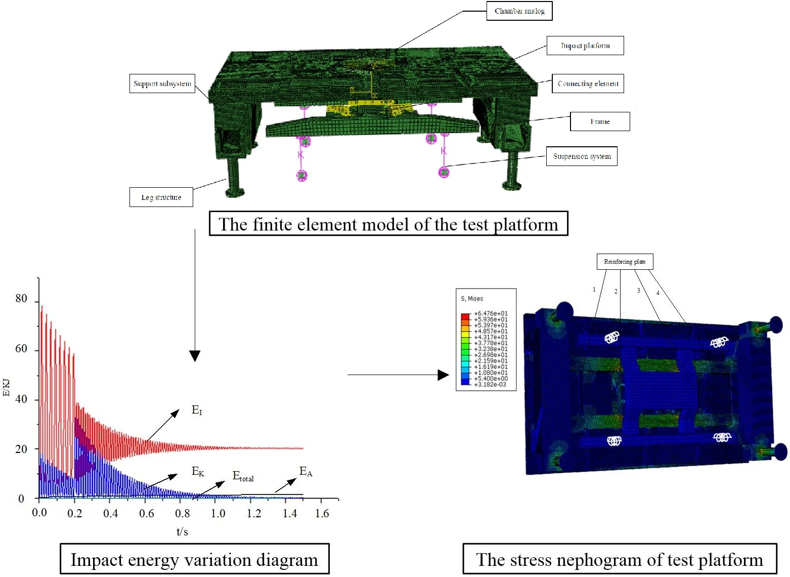
In this paper, the finite element model of impact test platform is established and analyzed by explicit central difference method. The relationship among different output energy has been obtained, which evaluated the validity of the finite element model and the simulation results. The total energy of the system is relatively constant. Meanwhile, there are two mutations in the kinetic energy, which is basically consistent with the experimental results. The energy change, stress and strain of the test platform during impact are analyzed. Ensure the strength of test platform meets the requirement.
Highlights
- The finite element model of impact test platform is established and analyzed by explicit central difference method.
- We evaluated the validity of the finite element model and simulation results depend on the relationship among different output energy.
- The energy change, stress and strain of the test platform during impact are analyzed.
1. Introduction
At present, there are many different methods to solve the dynamic problem of structure, among which the most used are direct integral method and modal superposition method. Since this paper adopts the direct integral equation, the modal superposition method is not introduced in detail. The direct integration method can be divided into two categories: implicit integration method and explicit integration method. The implicit integration method needs to directly solve the stiffness matrix of the structure subjected to the impact load. Implicit integration has methods of Newmark-β [1] and Wilson-θ [2]. The explicit integral method adopts the method of central difference, Uses the result of the previous incremental step to solve the next incremental step, and adopts the recursive method. For most of the structural impact dynamics problems, explicit integrals are generally used to solve them [3].
For the dynamic response analysis of a system, if the system is a system with damping, the intermediate variables need to be added, which will increase the overall calculation [4]. Implicit algorithm can also be transformed into explicit algorithm by using displacement as the variable of the first solution [5]. For explicit algorithms, Taylor expansion or weighted residual is usually used.
2. Finite element modeling of the test platform
The wave velocities of materials are calculated by using the properties of materials [6]. The equation is:
where E is Young modulus of material and ρ is the density of material.
In this paper, the dynamic response during the impact load process is mainly studied. The stress propagates along the direction of the load surface with time. In order to have a fine mesh density to capture the stress wave, the solid element is adopted for the test platform along the impact load direction and the design calculation is carried out. The designed test platform adopts steel structure. ρ = 7800 kg/m3, E = 2.1×10¹¹ MPa. Therefore, the wave velocity of impact platform material is:
Because the impact time of the hammer system is 0.2 s. It is appropriate to make the impact load occur within the span of 120 units. The height of the test platform is 1197 mm, and the minimum grid size is estimated to be 9.975mm by calculation. Therefore, the minimum grid size is set to be 10 mm to divide the test platform. The test platform is divided into grids by the combination of manual section method and automatic subdivision method. The results of cell grid generation are shown in Fig. 1.
Fig. 1The finite element model of the test platform
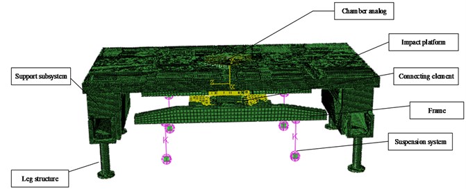
This model adopts metal materials. Detailed engineering materials of the test platform are shown in Table 1.
Table 1Detailed performance parameters of all parts and components
Name | Material | Poisson’s ratio | Ultimate strength (MPa) | Allowable stress (MPa) |
Chamber analog | Alloy steel | 0.3 | 980 | 557 |
Impact platform | Alloy steel | 0.3 | 980 | 557 |
Connecting element | Carbon structural steel | 0.27 | 390 | 160 |
Frame | Joist steel | 0.29 | 885 | 490 |
Support subsystem | Carbon structural steel | 0.27 | 390 | 160 |
Leg structure | Carbon structural steel | 0.27 | 390 | 160 |
3. Impact dynamics analysis of the test platform
The inherent period of the test platform is 0.036 s and the impact load duration is 0.2 s. By comparison, it can be found that the inherent period of the test platform is less than the duration of the impact load. Therefore, the impact studied in this paper is a complex impact category [7].
3.1. Load and boundary conditions
In the simulation of semi-rigid launch operation on the cold launch test platform, the impact load is provided by the hammer system on the vertical gantry, and the maximum impact load provided by the hammer system is shown in Fig. 2.
Fig. 2The impact load of the hammer system
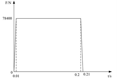
In the process of heavy hammer strike, the main force surface is the upper end surface of the simulant at the bottom of the initial volume chamber. A correlation point is set on the upper end surface of the simulator at the bottom of the initial volume chamber. Coupling constraints are established between the rigid node and the grid node at the upper end surface of the simulator at the bottom of the initial volume chamber. An associated point is set on the lower end surface of the hydraulic cylinder support structure, coupled with the mesh node on the lower end surface of the hydraulic cylinder, and the location of the associated point is completely fixed. In order to save calculation cost, 1.5s is taken in the analysis process.
3.2. Energy balance analysis
Energy balance analysis is an important part of explicit nonlinear dynamic analysis. By analyzing the relationship between the output energy, the validity of the finite element model and the simulation results can be judged and evaluated [8]. The energy balance equation of the whole model is as follows:
where EI is the internal energy; EV is the viscous loss energy; EFD is the friction loss energy; EKE is the kinetic energy; EW is the work done by the external loading; Etotal is the sum of these energy components.
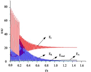
Through theoretical calculation and analysis, Etotal remains constant. There are errors in finite element calculations, Etotal is not a constant value but is generally less than 1 %. EI is mainly composed of energy loss EP in the inelastic process, pseudo-strain energy EA, recoverable elastic strain energy EE and energy loss ECD in the viscoelastic process [9]. Among them, pseudo-strain energy EA is the energy in transverse shear and the energy stored in hourglass resistance. In the simulation analysis, the proportion of pseudo-strain energy in the internal energy is generally no more than 5 %~10 % [10]. If the calculation results are beyond the scope, then the calculation results are unreliable and need to be re-calculated. During the impact process, the total energy, kinetic energy, internal energy and pseudo-strain energy of the system are shown in Fig. 3.
The total energy of the system remains at a constant value, and there is a sudden change in the kinetic energy of the test platform at about 0.001 s and 0.2 s, which is basically consistent with the fact. At 0.01 s, the hammer head of the heavy hammer system starts to contact the bottom of the initial capacity chamber on the platform. At 0.2 s, the hammer head of the heavy hammer system leaves the bottom of the initial capacity chamber. The ratio of pseudo-strain energy to internal energy was 7.89 %, which was between 5 % and 10 %, meeting the requirements. Through the analysis of energy output, the correctness of the finite element model of the test platform is verified.
Fig. 3Impact energy variation diagram
3.3. Transient response analysis
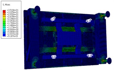
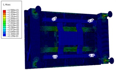
The time of impact loading is 0.2 s. The stress cloud diagram of the test platform extracted during the impact loading period is shown in Fig. 4.
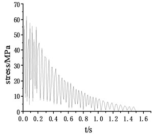
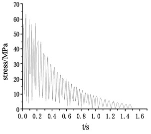
According to the stress cloud diagram, the stress of the test platform is mainly concentrated in the contact part which between the support structure and the Leg structure. The stress-time curve of the contact part (node 178375, 179438, 180487, 181550), as shown in Fig. 5.
Fig. 4The stress nephogram of test platform
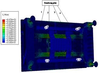
a) 0.04 s
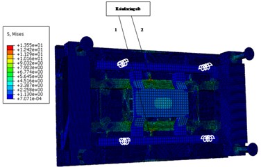
b) 0.08 s
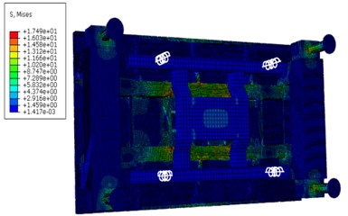
c) 0.12 s
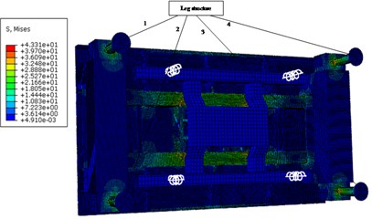
d) 0.2 s
e) 0.3 s
f) 0.4 s
Through the stress-time curve analysis of the contact nodes between the Leg structure and the support structure of the frame, the stress of the four support structures was consistent, reaching the maximum value of 68.5 at 0.04 s, meeting the yield strength of 160 under the safety factor of 1.5. The maximum strain was 0.000263, which was basically consistent with the stress distribution area. Within 0.2 s of the impact period, the stress oscillations changed, but the amplitude did not change very much. With the hammer system hitting, the stress gradually decreased and finally approached 0. The load area is mainly on the inner surface of the support structure close to the frame, which is caused by the large impact platform and the large span of the four support structures.
Fig. 5Stress – time curve of the contact point
a) Stress – time curve of node 178375
b) Stress – time curve of node 179438
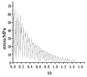
c) Stress – time curve of node 180487
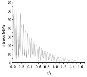
d) Stress – time curve of node 181550
4. Conclusions
By comparing the impact loading time of the hammer system, it is determined that the impact loading response is the category of complex impact. Using explicit dynamic calculation method, analyzes the changes of energy, the stress and strain in the process of impact. Through the analysis of the results, the design strength meet the requirements of experimental platform, the research content of this chapter for impact test of test platform has important guiding significance, and laid a solid foundation for the structural optimization.
References
-
Newmark N. M. A method of computation for structural dynamics. Journal of the Engineering Mechanics Division, Vol. 85, Issue 3, 1959, p. 67-94.
-
Wilson E. L., Farhoom I., Bathe K. J. Nonlinear dynamic analysis of complex structure. Earthquake Engineering and Structural Dynamics, Vol. 1, Issue 3, 2010, p. 241-252.
-
Bruns T. E. Zero density lower bounds in topology optimization. Computer Methods in Applied Mechanics and Engineering, Vol. 196, Issues 1-3, 2006, p. 566-578.
-
Zhang S., Zhang X. A new method in analyzing seismic response of the structure. Recent Developments in World Seismology, Vol. 6, Issue 1, 2009, p. 8-14.
-
Idesman A. V., Schmidt M., Sierakowski R. L. A new explicit predictor-multicorrector high-order accurate method for linear elastodynamics. Journal of Sound and Vibration, Vol. 310, Issue 1, 2008, p. 217-229.
-
Shi Jianxu, Chopp David, Lua Jim, Sukumar N., Belytschko Ted Abaqus implementation of extended finite element method using a level set representation for three-dimensional fatigue crack growth and life predictions. Engineering Fracture Mechanics, Vol. 77, Issue 14, 2010, p. 2840-2863.
-
Djerassi S. Three dimensional, one point collision with friction. Multi-body System Dynamics, Vol. 27, Issue 2, 2012, p. 173-195.
-
Chai Min, Luo Kun, Shao Changxiao, Chen Song, Fan Jianren DNS analysis of incipient drop impact dynamics using an accurate level set method. Chinese Journal of Chemical Engineering, Vol. 25, Issue 1, 2017, p. 1-10.
-
Dung Dao Van, Nam Vu Hoai Nonlinear dynamic analysis of eccentrically stiffened functionally graded circular cylindrical thin shells under external pressure and surrounded by an elastic medium. European Journal of Mechanics – A/Solids, Vol. 46, Issue 1, 2014, p. 42-53.
-
Rashidi Moghaddam M., Ayatollahi M. R., Berto F. Mixed mode fracture analysis using generalized averaged strain energy density criterion for linear elastic materials. International Journal of Solids and Structures, Vol. 120, 2017, p. 137-145.
About this article
The authors gratefully acknowledge the support from Education and Research Project for Young and Middle-aged Teachers in Fujian Province (Grant No. JT180597), Young teacher special project of Ningde Normal University (Grant No. 2018Q102), Ningde City Science and Technology Project (Grant No. 20170053), Major training project of Ningde Normal University (Grant No. 2017ZDK18) and Collaborative Innovation Center of Ningde Normal University (Grant No. 2017Z01).

