Abstract
Linear vibratory conveyors are common equipment to convey goods. They are used in different industries such as for example the building, mining and food industry. The systems are often used for the supply of bulk goods into further processing operations. The goods to be conveyed, typically requesting a heavy-duty design of the conveyor and eccentric excitation drives with relatively high torque. Often the motion of these conveyors is not ideal with reference to the conveying process of the bulk goods. Motion speed and amplitude of the goods are not constant and blocking effects as well as separation effects can occur. The target of this article is to determine a dynamic model for the targeted displacement of the centre of elasticity of a one-mass conveyor, enabling an optimal motion of the conveyor by an optimized set of springs, connecting the conveying element to the frame.
1. Introduction
Linear vibratory conveyors are mainly built to forward bulk material for the mining, building and food industry, such as rock, grit and flour. The assembly of these vibratory conveyors consists of two principal parts, the conveying element build as a conveying trough and a supporting element, build of steel elements and fixed to the ground by heavy-duty screws [1, 2]. Often, the conveying element is linked to the frame just be a set of springs. Such a system represents an efficient method for the generation of a micro-throw motion to the goods to be conveyed. Often, conveyors of this type are not intended to generate a constant motion regarding conveying speed and amplitude over the full length of the conveying element. This is mainly caused by the situation of the mass centre point and the centre of elasticity of such a conveyor. To eliminate this disadvantage, some linear vibratory conveyors are additionally equipped with a set of guiding levers between conveying element and Frame. Fig. 1 shows a typical one-mass vibratory conveyor without any guiding mechanism.
Fig. 1One-mass vibratory conveyor without guiding levers [own source]
![One-mass vibratory conveyor without guiding levers [own source]](https://static-01.extrica.com/articles/20185/20185-img1.jpg)
2. Applied methods
The theoretical solution is done in two steps. At first, a dynamic model is designed and then the dynamic parameters are determined.
2.1. Determination of the conveyors dynamic model
One-mass linear vibratory conveyors corresponding to the shown variant consisting of a conveying element which is connected to the base frame by four helical springs. Two eccentric drives are connected directly to the conveying element under a certain angle to the horizontal line. The eccentric dives turning clockwise (left drive in direction of material flow) and anti-clockwise (right drive in direction of material flow). These drives are self-centring and so a motion across the main forwarding direction is eliminated [3, 4].
Corresponding to the conveyor as shown in Fig. 1, the following general mechanical model can be of this conveyor type can be generated [5]:
Fig. 2Mechanical model of the vibratory conveyor [own source]
![Mechanical model of the vibratory conveyor [own source]](https://static-01.extrica.com/articles/20185/20185-img2.jpg)
2.2. Calculation of dynamic parameters
Assuming ξA=ξB, Eq. (1) can be converted to:
Based on this assumption, the following equations can be set up:
=-F0cosβF∙ρPFsinβPF+F0sinβF∙ρPFcosβPF.
Converted into the matrix form, the following matrices can be built.
For the mass:
For the stiffness of the springs:
The mechanical model described in Fig. 2, enables three degrees of freedom, i.e. a longitudinal motion in x-direction, a second longitudinal motion in z-direction and a rotation around the mass centre point, depending on the situation and effective direction of the excitation force and the centre of elasticity of the system. To ensure a pure linear motion under the intended excitation angle, it is necessary to avoid any kind of rotation around the mass centre point on this type of linear vibratory conveyor. As soon as a rotation takes place, the motion of the conveyed goods will be influenced in an unintended way, causing a suboptimal motion of the goods and a potential malfunction of the conveyor [6].
A mayor influence in this model comes from the damping conditions. Neglecting the horizontal components of the general model, the following equations can be formed for the values in z-direction.
For the displacement:
For the velocity:
and for the acceleration:
The velocity which is linked to the damping in the dynamic calculation of the system, represents the first derivation of the displacement and is the only component including a cosine function. For systems with very low damping, as given on a linear vibratory conveyor of the variant A, the following equations then can be formed:
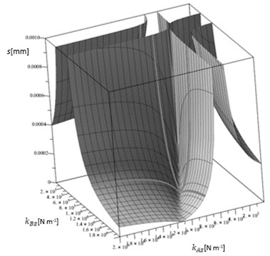
By the use of a numerical model, based on the Eqs. (11) to (13), a graph can be designed, showing the area of no-rotation. A valley between the stiffness kAZ and kBZ occurs and the intended amplitudes of the system can be selected by following the particular lines through the valley.
The following graph Fig. 4 for amplitude over stiffness in z-direction will be received.
Transmitting the requested design conditions for pure linear motion into the general model shown in Fig. 2, a conveyor with pure linear motion and no rotation around its mass centre point can be designed.
3. Results and discussions
To verify and validate the possibilities of modification on linear vibratory conveyors build on the mechanical model shown in Fig. 2, an existing conveyor is analysed and modified by changing the springs of the system. The stiffness of the springs is calculated based on the general Eqs. (3)-(5).
Fig. 3Amplitude over stiffness 3-D graph of a linear vibratory conveyor

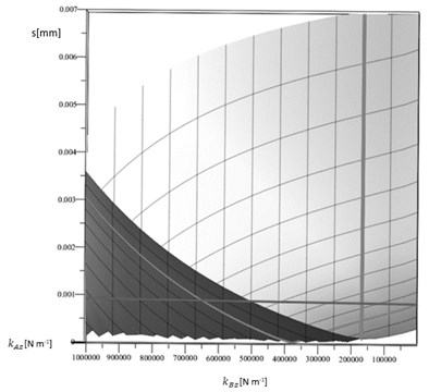
Fig. 4Rotation component of the amplitude in point A of the conveyor

In addition, the damping of the system has to be considered on the real conveyor. This is done by extending the equations by the terms corresponding to the damping of the system as follows:
+[(bAx-bBx)ξA+(bAx-bBx)ξB]∙˙φ=F0∙cos(ωFt),
+[(bAz-bBz)ξA+(bAz-bBz)ξB]∙˙φ=F0∙sin(ωFt),
+[(kAz-kBz)ξ2A+(kAz-kBz)ξ2B]∙φ+[(bAz+bBz)ξ2A+(bAz+bBz)ξ2B]
=-F0cosβF∙ρPFsinβPF++F0sinβF∙ρPFcosβPF.
Finally, all equations are converted into matrix form. For the mass matrix and the damping matrix, the equations will stay identical to Eqs. (6) and (7). For the damping, the following matrix has to be created:
3.1. Result of the analysis of the existing system
Following the graph in Fig. 4, kBx is situated in the area of no rotation while the amplitude for kAx corresponds to an amplitude of approximately 1.00 mm. That means, the rotating component of the motion in point A has an additional effect of 0.90 mm compared to point B.
Calculation and graph confirming the experience made during testing the system. So, the equations are verified as useful tool for the general analysis of linear vibratory conveyors of the analysed design. In a further step, the calculation model will be used for the determination of spring pairs, elimination the rotation component of the conveyor.
3.2. Calculation of the optimized conditions
To keep the compact and rigid design of the linear vibratory conveyor, the best possible solution to modify the conveyors motion would be a re-location of the centre of elasticity.
Keeping the mass conditions of the conveying element untouched and ensuring the damping conditions staying competitive to the presently existing once, a solution will be found by changing the stiffness conditions of the springs in the points A and B of the conveyor.
Focused on this modification possibility, three options of influencing the situation of the mass centre point with a simultaneous elimination of the rotation part of the motion are generally possible:
• Changing the stiffness kAz by replacing the springs in point A,
• Changing the stiffness kBz by replacing the springs in point B,
• Changing the stiffness kAz and the stiffness kBz by replacing all springs in points A and B.
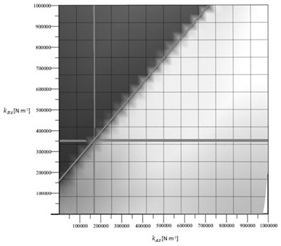
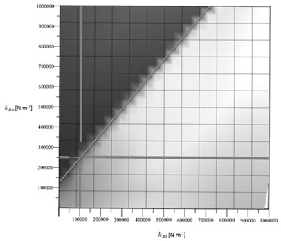
Based on this numerical calculation, a test series for the determination of the new situation of the centre of elasticity and the operation conditions is realised and the described modification possibilities are verified.
Fig. 5Corresponding stiffness kAz and kBz for the selection of test springs-different possibilities

a)

b)
4. Conclusions
In this paper, a dynamic model of a one-mass linear vibratory conveyor, conducted with the calculation of kinematic parameters for the model is determined. The result of the elaboration is a mechanical model, which can be used as base for the modification of the conveyors motion by situating the centre of elasticity optimal.
General equations for the model are developed and the final numerical system to calculate specific stiffness of springs for the targeted situation of the centre of elasticity of linear vibratory conveyors is introduced.
Based on the results of the paper, optimized parameters for the design of one-mass linear vibratory conveyors can be defined and simulated.
References
-
Harris C. M. Shock and Vibration Handbook. 5th edition, McGraw-Hill, New York, 2005.
-
Buja H. O. Praxishandbuch Ramm- und Vibrationstechnik. Bauwerk Verlag Berlin, 2007.
-
Dresig H., Holzweißig F. Maschinendynamik 8. Auflage, Springer Verlag, Berlin, 2008.
-
Knaebel M., Jäger H., Roland Mastel Technische Schwingungslehre. 7. Auflage, Vieweg+Teubner Verlag, Wiesbaden, 2009.
-
Pešík M. Function and Performance Optimization of Vibration Conveyors. Ph.D. Thesis, Liberec, 2013.
-
Griemert R., Römisch P. Fördertechnik. Springer Fachmedien Wiesbaden, 2015.

