Abstract
This work focuses on the quasi-static behavior study for simply supported sandwich beams with aluminum faces and magnetorheological elastomer core subjected to three points bending subjected to a magneto-mechanical loading by numerical and experimental investigations. The mechanical properties of the magnetorheological elastomer core are measured experimentally and the mechanical behavior of the MRE was identified by the generalized Maxwell rheological model. Depending upon the adjustable properties of the beam, energy dissipation is by core shear. A systematic series of experiments and finite elements simulations have been performed in order to assess the static behavior of the beam. The results obtained show a significant influence of the magnetic field intensity on the flexural displacement of the beam.
Highlights
- A smart base isolation system is developed by exploiting the uniqueness of MRE seismic isolators.
- Testing results reveal the superiority of the active control based in MRE isolation system.
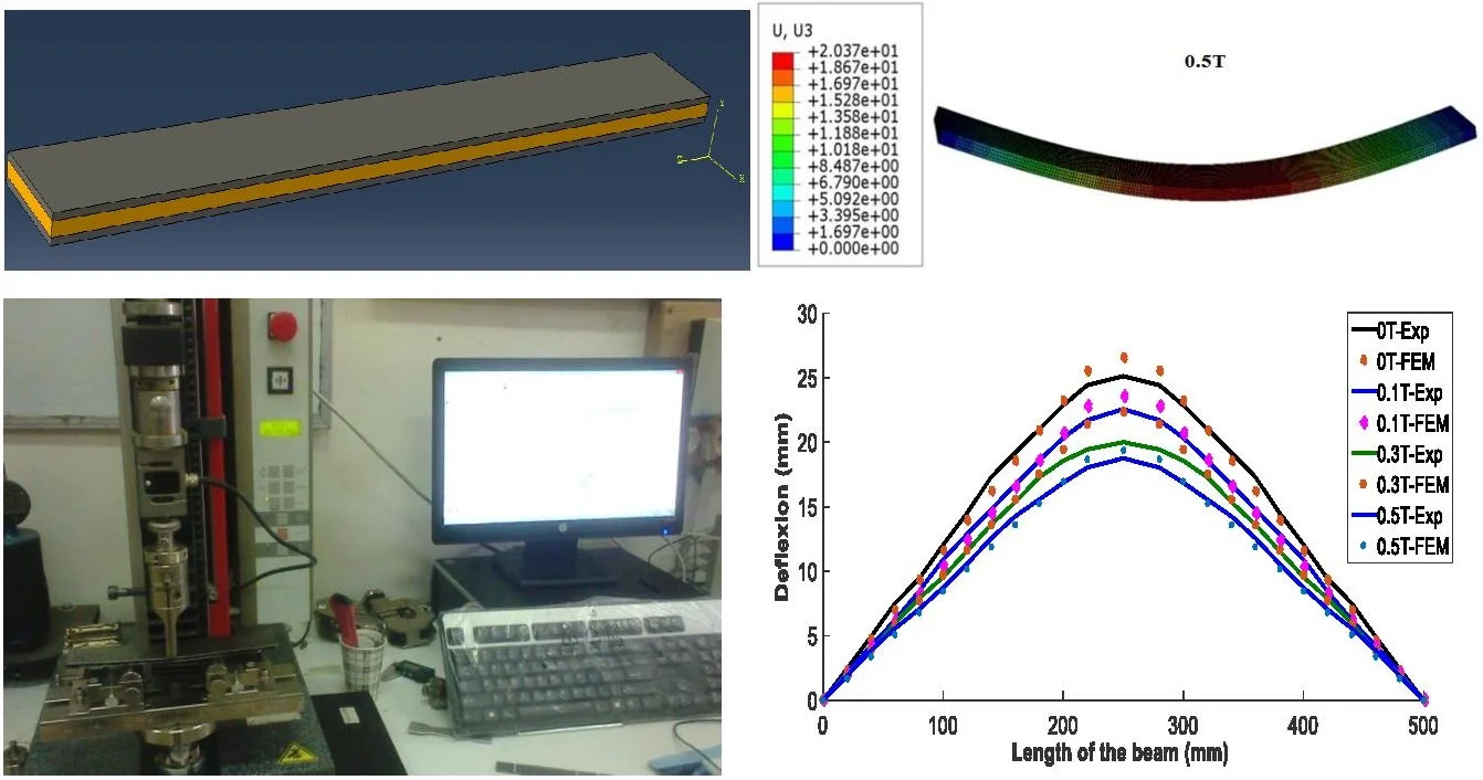
- Quasi-static behavior of the beam is controlled by magnetic field.
- The sandwich beam has potentials for controlling the displacements of seismic waves.
1. Introduction
Innovative control systems in the field of civil and mechanical engineering have become in recent years of great importance, they allow to design structures to resist, without significant damage, to dynamic actions, for example storms, great seismic action, etc. At the same time, it is required during construction to protect the structures by effective and reliable protection systems by reducing the seismic response. Among these innovative control systems, three different approaches can be distinguished: the passive, semi-active and active control system. Magnetorheological elastomer (MRE) has attracted increasing research interest for the application in semi-active base isolation system to protect structures from seismic vibrations [1]. As known, the most intended gain of base isolation is to decouple the superstructure from hazardous ground motions by introducing lateral flexibility to the base layer [2, 3]. However, maximal level of decoupling may lead to a common issue, which is excessive base drift in traditional base isolation system [4].
Materials for which rheological properties can be controlled by the application of a magnetic field are called magnetorheological materials (MR) [5-7]. They belong to the class, more widely defined, active materials since they can respond to changes in their environment, changes brought here by semiconductors and appropriate control algorithms. Such materials can be used directly in devices or incorporated into composites to create advanced composite structures, making their multiple applications in the automotive, aerospace and electronics industries. The magnetorheological elastomers (MRE) consist of ferromagnetic particles (generally of micrometric size) dispersed in a silicone elastomeric matrix [8-12]. Their low response time (on the order of one milliseconds), their continuously controllable properties, and their ability to withstand wide variations in rigidity make MRE attractive for potential applications in aerospace, automotive, civil engineering or in electrical engineering [13-17]. Examples include adaptive lenses, interactive man-machine interfaces, damping devices and variable stiffness supports. Thus, the development of the use of composite materials in structures requires putting in place the necessary tools for modeling the dynamic [18, 19] or static [20] behaviors of new structures such as sandwich structures in magnetorheological elastomer. In civil or mechanical engineering, the search for effective damping in a wide range of vibration frequencies is a critical issue to prevent human and material losses. First, we stuck to incorporate elastomers because they certainly reduce vibration and noise, but their stiffness and damping capacities can be adjusted independently. Today it is possible to go further with the so-called magnetorheological materials: controlled by magnetic field, they can change continuously, quickly and reversibly some of their characteristics and adapt to a new environment [21]. Zhou and Wang [22, 23] formulated an analytical model of the vibrating motion of a sandwich beam under a uniform magnetic field, perpendicular to the direction of the thickness. To validate the analytical model, they conducted a second study based on numerical modeling to control the rheological properties. Dwivedy et al. [24] studied the parametric instability areas of a sandwich beam with a magnetorheological elastomer core identical to that studied by Zhou and Wang [18, 19], but subjected to a periodic load, to determine the adjustment advantages of the mechanical properties of the loaded elastomers exposed to a magnetic field. Nayak et al. [25, 26] studied the vibration reduction of a sandwich beam with three cores, an unloaded elastomer core, a loaded elastomer core with ferromagnetic particles, and a loaded core with carbon particles. Areas of parametric instability for the two different types of particle loading were studied only for the first three vibration modes to illustrate the passive and active vibration reduction. Dyniewicz et al. [27] in their paper dealt with the semi-active control of the vibrations of structural elements. Elastomer composites with ferromagnetic particles that act as magnetorheological fluids are used. The damping coefficient and the shear modulus of the elastomer increase when it is exposed to an electro-magnetic field. This technique reduces vibrations more effectively than if the elastomer was permanently exposed to a magnetic field. Zuguang Ying et al. [28] have developed an advanced magnetorheological elastomer structure to control vibrations. Sun et al. [29] investigated the controllable capability of an adaptive MRE sandwich beam; the experimental investigations showed that the MRE damps unwanted motion. Hu et al. [30] conducted an experimental study on the dynamic response of a sandwich beam containing two aluminum layers with a MRE core under non-homogeneous magnetic fields; it was shown that a reduction of 13.9 % is achieved on the first mode of transverse motion. More recently, the semi-active control of a MRE sandwich beam was investigated under different loadings [31]; results showed the changing stiffness and damping of the MRE layer controls the motion amplitude. Yanxiang Wan et al. [32] determined the properties of the magnetorheological elastomer by dynamic analysis (DMA) under different conditions. The results show that the transition behavior of the silicon rubber based MRE samples under uniaxial compression occurs at about 50 °C. The storage modulus exhibits two different trends with the temperature variation: It first decreases rapidly and then increases slightly or maintains a stable value with increasing temperature. Schümann et al. [33] used X-ray microtomography to analyze the microstructure of particles in the presence of magnetic fields. The situation of the sample during mechanical testing was recreated during tomography to observe the particle microstructure under the exact circumstances of occurring magnetorheological effects. A significant impact of the magnetic field and the strain on the rotation of the particles and their radial distribution was verified. Almeida et al. [34] studied the effectiveness of MREs to control wave motion in a one-dimensional structure. It is shown that the MRE can be used to control the amplitudes of the reflected and transmitted waves from the section of beam containing the MRE. Felipe et al. [35] realized free and forced vibration tests under different magnetic field intensities to evaluate the dynamic properties of MRE sandwich beams. The experimental results show a favorable reduction of mechanical vibrations, especially on the fundamental mode of the structure. That MRE sandwich beam shifted the natural frequencies and amplitude of vibration due to the increase of an induced magnetic field.
Given the human and material damage caused by the earthquake (Algeria May 21, 2003, Japan March 11, 2011, Indonesia August 5, 2018). In this paper, a smart base isolation system is developed by exploiting the uniqueness of MRE seismic isolators. As mentioned below, an MRE-based beam damper is developed to adjust the parameters of this real-time isolator. A numerical and experimental investigation has been conducted to evaluate the seismic protection performance of the MRE isolation system comparing fixed base building; passive base isolated structure and Bang-Bang controlled base isolated structure. Testing results reveal the superiority of the active control based in MRE isolation system. In this work, the time response from the structure en MRE with applied of maximal force to the generation of the desired applied magnetic field intensity of is less than 3s, satisfying the requirement of real-time structural control.
2. Mathematical modeling of bending mechanical behavior
In this section it is considered a simply-simply supported (S-S) beam exposed to a uniformly distributed magnetic field (see Fig. 1). Geometry of a sandwich beam in three-point bending and the different characteristics of each layer are illustrated in Fig. 2.
Fig. 1Schematic of the sandwich beam with magnetorheological elastomer
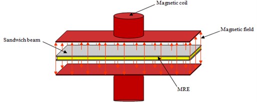
Fig. 2a) Geometry of a sandwich beam in three-point bending, b) geometrical schematic of a sandwich beam elements

a)

b)
The boundary conditions are given as follows:
In order to best represent the static behavior of the beam without resorting to complex theories of higher order, the Nilsson model, taking some of the principles from the Timoshenko theory, [36] will be used. However, Nilsson’s works were interested in a sandwich structure where skins are homogeneous materials.
In this case, if the equilibrium equation, written as a function of the longitudinal elasticity and the shear moduli of the beam, is given by:
wherein the expression of the transverse shear angle along the axis is given by:
with:
By integrating Eq. (2) we deduce the following expression of φ(x):
The symmetry of the beam requires:
by substituting Eq. (4) into Eq. (1) we obtain:
Finally, by the integration of Eq. (5), the response of the magneto-visco-elastic behavior of the Timoshenko beam is given in the form:
+12(GA)eq(F-B2bhjμej∂w2j∂x2)x,
where (EI)eq and (GA)eq are the bending and shear rigidity of beam respectively.
The maximum deflection is given for x=L/2 as follows:
In this study, we assume that the rigidity of the magnetorheological elastomer is very low in the x-direction. In the y-direction, it shall be sufficient to ensure the displacement in phase of the two skins. The flexural rigidity per unit width of the beam is calculated by:
(EI)eq=Eb((hc2)33-(-hc2-h)33)+Ec((hc2)33-(-hc2)33)
+Et((hc2+ht)33-(hc2)33),
with:
where: hb=ht=h, Eb=Et=Ep, and its equivalent shear stiffness (GA)eq is expressed as:
3. Finite element simulation
3.1. Identification of viscoelastic materials under Abaqus
For viscoelasticity materials the response is time dependent. Conceptually, the stress response at time t reads in time domain (following the Abaqus Manual):
where R is the relaxation modulus and ˙ε is the strain rate. When the stress and strain variables are interpreted in the sense of the previous section, the relaxation moduli can be interpreted as time dependent representations of the bulk and shear moduli as:
which employ Prony series expansion with instantaneous moduli, K0; G0; M0 relative relaxation moduli, ki, gi, gi and characteristic times τKi, τGi, τMi, respectively, for the Prony terms with index i.
For the case of the bulk contribution, Eq. (11) reads together with the bulk relaxation modulus:
where the expressions in the summation are the contributions by the Prony terms i to the volumetric ‘‘creep’’ strain:
Finally, the volumetric stress stain relation reads:
by introducing the volumetric “creep strain”:
Equivalent relations can be given for the deviatoric behavior with respect to G(t) and M(t), which give rise to three equations for the diagonal elements and three equations for the off-diagonal elements, respectively, of the stress and strain deviators.
The creep strain contributions, εvoli (and their deviatoric equivalents), are interpreted as state variables.
3.2. Finite element method implementation and response calculation
The Abaqus interface for “user supplied material laws” only allows for formulations of constitutive material laws in the time domain (Section 3.1). The implementation follows the Abaqus Manual pretty closely; extensions and modifications concern material symmetry. The characteristic times τKi, τGi, τMi need not to be equal for Prony series since their effects are entirely separated. The maximum number of Prony terms is set to 13. No temperature dependence is included. Extensive single element testing has been conducted to verify the implementation. Since the effects of the contributions by the bulk behavior and the two shear behaviors can be decoupled, these effects have been tested separately. This is also possible for the verification of the response of a constitutive law according to the generalized Maxwell model. For the shear behavior of magnetorheological elastomer the decoupling properties can be utilized to define loading scenarios in which either solely G or solely M will be “activated”.
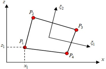
The calculation of structures by finite elements is performed using the Abaqus software. The element used is a 2-D element, CPS4 type with four nodes (Fig. 3).
Fig. 3Mesh element in Abaqus: 2D type CPS4
The sandwich material is modeled by three structures, two isotropic elastic structures corresponding to the aluminum skin, and a MRE core. The skins are characterized by the Young’s modulus, Poisson's ratio and density, given in Table 1. The mechanical and rheological characteristics of the MRE measured experimentally were given by [18]. The identification of the magnetorheological elastomer by Abaqus software were performed taking into the rheological characteristics of the MRE according to different magnetic field intensities using the Prony series and the generalized Maxwell model at six-branches.
The sandwich beam model realized in Abaqus is given in Fig. 4.
Table 1Mechanical, electrical and geometrical properties of the beam
Material properties | ρ (kg/m3) | E(MPa) | ν | μej (Hm-1) |
Aluminum skins | 2800 | 72000 | 0.33 | 1.2566650×10⁻⁶ |
Elastomer | 1100 | 1.7 | 0.45 | – |
Geometrical characteristics of the top (t) and bottom (b) skins | ||||
b (mm) | L (mm) | ht (mm) | hb (mm) | – |
30 | 500 | 1 | 1 | – |
Geometrical characteristics of the elastomer | ||||
b (mm) | L (mm) | hc (mm) | – | – |
30 | 500 | 2 | – | – |
Fig. 4Model of the sandwich beam in Abaqus, without mesh and with mesh


The results of meshing of the beam in Abaqus are given in Table 2.
Fig. 5 shows the deflection of the composite material structure for different values of the magnetic field. These values of the magnetic field are chosen according to the capacity of the coil used in the experimental part (0.1 T, 0.3 T and 0.5 T).
Fig. 5Deflection obtained by finite elements for different values of the magnetic field


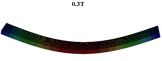

Deflection obtained by finite elements for different values of the magnetic field through the distance between supports is given in Fig. 6, for different values of magnetic field. It is observed that the deflection of the beam is strongly dependent on the magnetic field and its value decreases with the increase of the magnetic field intensity, for L/2= 250 mm it has a value of deflection of 27.820 mm for a value of B= 0 T and a 23.350mm for B= 0.3 T and a value of 20.370 mm for B= 0.5 T.
The deflection values obtained are presented in Table 3.
Fig. 6Deflection obtained by numerical simulation for different values of the magnetic field
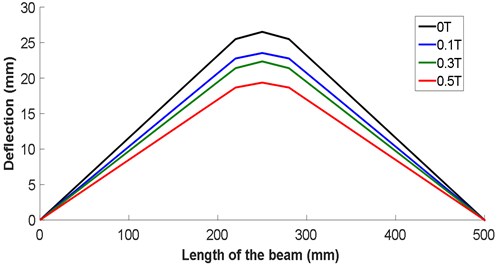
Table 2Problem size of meshing by FEM
Number of elements | 16000 |
Number of nodes | 21105 |
Number of nodes defined by the user | 21105 |
Total number of variables in the model | 63315 |
Table 3Deflection obtained by finite elements for different values of the magnetic field
x (mm) | w (mm) | |||
0 T | 0.1 T | 0.3 T | 0.5 T | |
20 | 02.318 | 02.070 | 01.946 | 01.697 |
40 | 04.637 | 04.140 | 03.892 | 03.395 |
60 | 06.955 | 06.210 | 05.837 | 05.092 |
80 | 09.274 | 08.280 | 07.783 | 06.790 |
100 | 11.590 | 10.350 | 9.7290 | 08.487 |
120 | 13.910 | 12.420 | 11.670 | 10.180 |
140 | 16.230 | 14.490 | 13.620 | 11.880 |
160 | 18.550 | 16.560 | 15.570 | 13.580 |
180 | 20.870 | 18.630 | 17.510 | 15.280 |
200 | 23.180 | 20.700 | 194600 | 16.970 |
220 | 25.500 | 22.770 | 21.400 | 18.670 |
250 | 27.820 | 24.840 | 23.350 | 20.370 |
4. Experimental analysis
4.1. Elastomer development procedure (MRE)
For the charged elastomers, the implementation is a decisive step because it conditions the incorporation and the homogeneous dispersion not only of the reinforcing charges but also of the various ingredients of the formulation.
4.1.1. Choice of ingredients
This part details the constituents used to elaborate the magnetorheological composites. The nature of the elastomer (RTV141) and the charges, as well as the structuring protocol of the particles under magnetic field will be explained.
4.2. Matrix
The realization of a structured composite material cannot be done under any conditions. Firstly, the elastomer must have good mechanical properties but also a low viscosity before crosslinking to facilitate the dispersion and structuring of the charges. A cold or moderate temperature crosslinking is a clear advantage because it facilitates the implementation of structuring under magnetic field. The choice was made on a silicone elastomer marketed by Rhodorsil: RTV 141. The characteristics of this elastomer are given in Table 4.
The RTV141 polymer has a sufficiently low viscosity so that the dispersion of 40 % of charge remains easy. The hardening time of the RTV 141a was measured on a Haake RheoStress 600 rheometer, thermoregulated at 75°.
Table 4Characteristics of this elastomer RTV141
Primary | Catalyst | Mixed | |
Viscosity (Pa.s) | 3.5 | 0.65 | 4 |
Young’s modulus (kPa) | – | – | 700 |
Elongation at break | – | – | 120 % |
Release time (h) | – | – | 4 (60°) 2 (100°) |
Density | – | – | 1.02 |
Color | Transparent | Transparent | – |
4.2.1. Charge
The charges must be magnetic, a size of about one micron. If larger particles are used, problems of cracking [23] and sedimentation appear while the number of chains decreases. For this, our choice of particles was fixed on Prolabo Normapur iron with high purity (99.5 %), whose average size is 2.5 μm, the magnetization saturation is 1800 kA/m and the relative permeability is close to 1000 [24]. The characteristics of this elastomer are given in Table 5.
Table 5Particle characteristics
Iron 99.5 | Fe % | Insoluble impurities |
99.5 | 0.1 |
4.2.2. Elastomer elaboration
4.2.3. Isotropic composite
The development of the isotropic composite follows a protocol that aims to best disperse the particles in the matrix, while breaking up a maximum of agglomerates. The particles retained are Prolabo iron with 99.5 % purity, so as to facilitate the chemical treatments of the charges. The matrix is an RTV141 silicone elastomer marketed by Rhodia and will perceive its good flowability, which is used for the highest charge rates; its crosslinking is ensured by heating at 70 °C via a heating resistor connected to a 0-240 V autotransformer. The heating resistor, a Jouimin FCF 200 W Acim, is cold-formable and has been modeled to heat evenly the isotropic sample.
The first step consists of a particle treatment which aims either to graft the particles of an adhesion promoting agent or to degrease the fillers (pre-treatment).
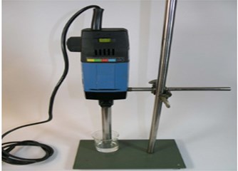
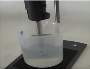
The particles are then dispersed in the matrix (25 %) by volume (Eq. (19)). The mixture is then sheared for one hour using a turax (Fig. 7) to break up a maximum of agglomerates. A catalyst is added to the mixture to initiate crosslinking of the elastomer, and the whole is degassed under vacuum for 10 minutes. This last step is important because the imprisonment of small air bubbles in the elastomer clearly harms the mechanical properties of the set.
Finally, the mixture RTV141+charges is poured into a glass mold. To protect against accidental bonding between the sample and the mold, the glass is covered with a heat-resistant silicone non-stick agent (Brenntag Sil-Vert, usable between –40 and +204 °C). The jaws are made of duraluminium and covered with an adhesive primer (4094 a primer provided by Rhodia Silicones): simply deposit a thin liquid film on the area to be treated and allow to dry 30 minutes before mold the polymer.
Fig. 7Ultra-turrax homogenizer
The volume fraction or charge rate is the ratio of the volume of the charges to the total volume of the mixture:
The elaborated elastomer is given in Fig. 8.
The ingredients in terms of volume fractions of each MRE are given in Table 6.
Fig. 8Elastomer composite elaborated
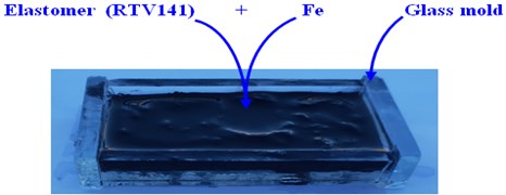
Table 6Constituents of the magnetorheological elastomer
Time of reticulation in hours | mSiliconOil (g) | mRTV(A) (g) | mFe (g) | mRTV(B) (g) |
Charged elastomer to 25 % ferromagnetic particles | ||||
30 h | 1.23 | 1.193 | 5.339 | 1.191 |
4.2.4. Elaboration of the magnetorheological anisotropic composite
The development of a structured anisotropic composite material consists in the creation of a structure of column of magnetic particles as perfect as possible within the elastomer.
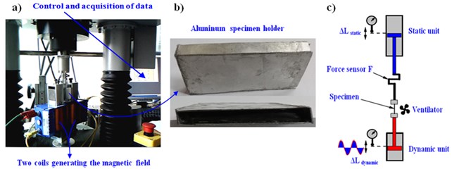
In this section we have repeated the same steps of elastomer composite fabrication (Section 2.2.1), but in this section an aluminum specimen holder has been manufactured to guarantee the transmission of the magnetic field, shear stress and the dimensions of the test piece (Fig. 9(b)). This specimen holder is placed between two coils to generate a variable magnetic field. This mechanism is mounted in a dynamic mechanical analysis machine, equipped with a suitable software that is used to determine the parameters studied below. Fig. 3 shows the essential parts of the device which is composed of:
1. Aluminum specimen holder (Fig. 10(a) and (b));
2. Two coils for magnetic field generation (Fig. 10(a));
3. An upper unit which permits to apply a static load, being controlled in displacement / deformation or in force / stress (Fig. 10(c));
4. A lower unit which permits to apply the dynamic parameters with a frequency of 1 Hz to 1000 Hz, being controlled in displacement / deformation or in force / stress (Fig. 10(c));
5. A fan allowing temperature-controlled tests (Fig. 10(c)).
Fig. 10Description of the experimental device
4.2.5. Elaboration of the magnetorheological sandwich beam
After evaluating the influence of the magnetic field on the elastomer comprising 25 % volume of iron particles, and given the lack of literature on magnetorheological sandwich beams, we found it particularly interesting to study the influence of the magnetic field on the vibrational behavior of these beams. The objective was to develop a sandwich beam containing an MRE with micro sized iron particles at a volume fraction of 25 %. The particles had to be aligned before crosslinking under the effect of a constant magnetic field to obtain a structure with viscoelastic properties that can be tuned by a magnetic field applied externally.
4.2.6. Implementation of the preparation
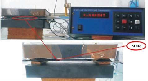
A rubber mold of rectangular form, 15 cm in length, 3 cm in width and 2 mm in thickness, was bonded to the lower aluminum skin of the beam (Fig. 11(a)). Dough of the elastomer was injected into the mold (Fig. 11(b)). The upper skin on the elastomer was bonded to prevent separation (Fig. 11(c)). The beam obtained was subjected to a perpendicular constant magnetic field (0.14 T) so that the ferromagnetic particles could be aligned during the crosslinking of the elastomer (Fig. 12).
Fig. 11Steps in fabricating the MRE beam

a) Aluminum top and bottom skins

b) Injection elastomer into the mold

c) MER beam
Fig. 12Device for manufacturing elastomer beams loaded with 25 % by volume of iron particles
4.3. Three-point bending of the beam – experimental test stand
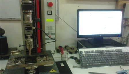
The experimental tests were conducted in the laboratory of the Research Unit Materials - Processes and Environment UR-MPE University of Boumerdes. The dimensions of beam are shown in Table. 1, the distance between the supports is around of 300 mm, the distance between supports and the ends of beam is around of 150 mm. Zwick 2.5 kN strength test machine with a macro extensometer was used for strength tests of beams. These tests are carried by varying the intensity of the magnetic field (0, 0.1, 0.3 and 0.5 T) with a speed of displacement of 1 mm mn-1.
The beam was investigated using a test stand specially designed for three-point bending strength tests. The test stand is shown in Fig. 13. The obtained results are presented in the form of plots and tables. The aim of the presented section is validation of developed numerical model.
Sandwich specimens of size 500 mm×30 mm×4 mm are manufactured using two aluminum skins of 1 mm thickness and an elastomer core charged at 25 % by ferromagnetic particles of micrometric size is inserted between the two skins (Fig. 11(c)). The sandwich beam was manually assembled by gluing the aluminum skins onto the magnetorheological elastomer core using two-component RTV141B adhesive. Mechanical, electrical and geometric characteristics aluminum and the MRE are listed in Table 1.
Fig. 13Photography of the three-point bending test machine
4.3.1. Interpretation of the results (force/displacement)
The force-displacement curve of the beam subjected to a three-point bending load is given in Fig. 14. From this curve, it can be seen that the breaking force is about of 115 N for the test of the part subjected to a magnetic field intensity of zero. On the other hand, the specimen subjected to a magnetic field intensity of 0.5 T is quite far from the rupture. It can be clearly seen that the rupture of the last specimen is not yet reached even for the value of the maximum applied force (around 150 N) during the test.
As well as the curve in Fig. 14 shows that specimens exhibit non-linear behavior, even at small deformations. It is possible to define separate domains:
For the test piece subjected to a magnetic field intensity of 0 T, we can observe a behavior more or less linear at the beginning of displacement and for a force value less than 20 N, then a non-linear behavior until the rupture. On the other hand, the specimen subjected to a magnetic field intensity of 0.5 T presents a non-linear behavior even with practically negligible displacements.
Deflection obtained by experimental analysis for different values of the magnetic field through the distance between supports is given in Fig. 15, for different values of magnetic field. It is observed that the deflection of the beam is strongly dependent on the magnetic field and its value decreases with the increase of the intensity of magnetic field, for L/2= 250 mm it has a value of deformation of 25.929 mm for a value of B= 0 T and a 21.483 mm for B= 0.3 T and a value of 19.581 mm for B= 0.5 T.
The deflection values obtained are presented in Table 7.
Fig. 14Three-point bending strength / displacement curve of the sandwich beam with and without magnetic field intensity
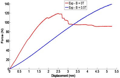
Fig. 15Deflection obtained by experimental analysis for different values of the magnetic field
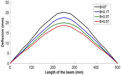
Table 7Deflection obtained by experimental analysis for different values of the magnetic field
x (mm) | w (mm) | |||
0 T | 0.1 T | 0.3 T | 0. 5 T | |
20 | 02.453 | 02.196 | 02.007 | 01.894 |
40 | 04.943 | 03.801 | 03.048 | 02.889 |
60 | 07.538 | 06.232 | 06.002 | 05.586 |
80 | 09.425 | 08.458 | 07.897 | 07.064 |
100 | 12.062 | 10.910 | 09.567 | 08.752 |
120 | 14.537 | 12.489 | 11.584 | 10.586 |
140 | 16.836 | 14.794 | 13.627 | 12.562 |
160 | 17.948 | 15.925 | 15.364 | 14.267 |
180 | 20.852 | 18.586 | 16.297 | 15.567 |
200 | 21.858 | 20.351 | 18.564 | 16.867 |
220 | 24.432 | 21.708 | 19.438 | 18.285 |
250 | 25.929 | 23.496 | 21.483 | 19.581 |
5. Comparison of the deflections obtained experimentally and by finite elements simulation
Fig. 16 shows the curves of the deflection obtained experimentally and those obtained by finite elements as well as the differences. The latter does not exceed 10.7 % for B= 0 T, 10 % for B= 0.1 T, 16.7 % for B= 0.3 T and 14.55 % for B= 0.5 T. This difference can be attributed to the side effects of the magnetic field on the MRE behavior, which are ignored by the numerical simulation.
The comparison of the error ratio of the deflection obtained by the experimental analysis and numerical simulation are listed in Table 8. It is noted that the deflection values obtained by the two methods are confronted with an error rate not exceeding 16.67 %.
Fig. 16Comparison of the deflection obtained by experimental analysis and by finite elements simulation for different values of the magnetic field
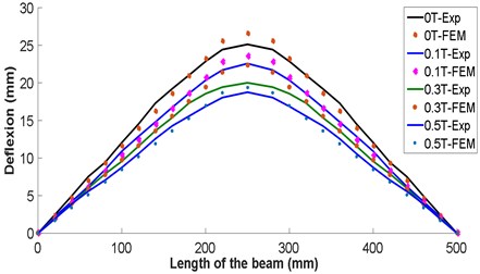
Table 8Comparison of the experimental deflections and those obtained by finite elements
B= 0 T | B= 0.1 T | B= 0.3 T | B= 0.5 T | |||||||||
x (mm) | EXP | FEM | ∆ % | EXP | FEM | % | EXP | FEM | % | EXP | FEM | % |
20 | 02.45 | 02.31 | 05.82 | 02.19 | 02.07 | 06.08 | 02.00 | 01.94 | 03.00 | 01.89 | 01.69 | 11.61 |
40 | 04.94 | 04.63 | 06.60 | 04.20 | 04.14 | 01.47 | 03.77 | 03.89 | 03.00 | 03.88 | 03.39 | 14.55 |
60 | 07.53 | 06.95 | 08.38 | 06.23 | 06.21 | 00.35 | 06.00 | 05.83 | 02.83 | 05.58 | 05.09 | 09.70 |
80 | 09.42 | 09.27 | 01.63 | 08.45 | 08.28 | 02.15 | 07.89 | 07.78 | 01.46 | 07.06 | 06.79 | 04.00 |
100 | 12.06 | 11.59 | 04.07 | 10.91 | 10.35 | 05.41 | 09.56 | 09.72 | 01.70 | 08.75 | 08.48 | 03.12 |
120 | 14.53 | 13.91 | 05.93 | 12.88 | 12.42 | 03.78 | 11.58 | 11.67 | 00.70 | 10.58 | 10.18 | 03.99 |
140 | 16.83 | 16.23 | 03.73 | 14.79 | 14.49 | 02.10 | 13.62 | 13.62 | 00.05 | 12.56 | 11.88 | 05.74 |
160 | 17.29 | 18.55 | 07.25 | 16.72 | 16.56 | 01.00 | 15.36 | 15.57 | 01.34 | 14.26 | 13.58 | 05.06 |
180 | 20.85 | 20.87 | 00.08 | 18.58 | 18.63 | 00.23 | 17.29 | 17.51 | 01.23 | 15.56 | 15.28 | 01.88 |
200 | 21.01 | 23.18 | 10.30 | 20.35 | 20.70 | 01.70 | 18.56 | 1946 | 04.83 | 16.86 | 16.97 | 00.60 |
220 | 24.43 | 25.50 | 04.40 | 21.70 | 22.77 | 04.90 | 19.43 | 21.40 | 10.00 | 18.04 | 18.67 | 03.46 |
250 | 25.12 | 27.82 | 10.70 | 22.57 | 24.84 | 10.00 | 20.01 | 23.35 | 16.67 | 18.76 | 20.37 | 08.58 |
6. Conclusions
A formulation based on the Timoshenko beam theory is put in place to describe the static behavior of the beam. Numerical simulation and experimental were done of 3-point bending analysis in order to evaluate the bending stiffness by varying the intensity of the magnetic field. The main conclusions drawn from this work are as follows:
1) The quasi-static behavior of the beam is controlled by the adjustment of the rheological properties of the magnetorheological elastomer.
2) The energy dissipation is influenced by the shearing of the sliding motion between the micro-particles of iron generated by the effect of the intensity of the magnetic field. This is the essential factor to reduce earthquake wave displacements.
3) The results found show that the intensity of the magnetic field has a very important influence on the rigidity of the magnetorheological elastomer (the global bending rigidity of the MRE-based sandwich beam increases with increase of the applied magnetic field); this influence is due to the repulsive attractive force between the ferromagnetic particles.
4) It should also be noticed that the quasi-static model cannot deal with a local and transient effect that occur under dynamic loading. We did not analyze the dynamic factors such as strain rate effect and inertial effect. These effects may be significant when the impact velocity is high. Also, the range of impact velocities within which the quasi-static model is valid is of interest.
5) The above conclusions reveal that the proposed sandwich beam exhibits promising controllable property. Since the bulk stiffness of the sandwich can be widely increased by the applied magnetic field, the proposed sandwich beam holds potentials for developing applicable semi-active devices for earthquake wave displacements control.
References
-
Li Y., Li J., Li W., Du H. A state-of-the-art review on magnetorheological elastomer devices. Smart Materials and Structures, Vol. 23, Issue 12, 2014, p. 123001.
-
Kelly J. M. Aseismic base isolation: review and bibliography. Soil Dynamics and Earthquake Engineering, Vol. 5, Issue 4, 1986, p. 202-216.
-
Naeim F., Kelly J. M. Design of Seismic Isolated Structures: From Theory to Practice. John Wiley and Sons, 1999.
-
Nagarajaiah S., Narasimhan S. Smart base-isolated benchmark building. Part II: phase I sample controllers for linear isolation systems. Structural Control and Health Monitoring, Vol. 13, Issues 2-3, 2006, p. 589-604.
-
Gibson R. F. A review of recent research on mechanics of multifunctional composite materials and structures. Composite Structures, Vol. 92, Issue 12, 2010, p. 2793-2810.
-
Mikhasev G. I., Altenbach H., Korchevskaya E. A. On the influence of the magnetic field on the eigenmodes of thin laminated cylindrical shells containing magnetorheological elastomer. Composite Structures, Vol. 113, 2014, p. 186-196.
-
Nayak B., Dwivedy S. K., Murthy K. R. K. Dynamic stability of a rotating sandwich beam with magnetorheological elastomer core. European Journal of Mechanics – A/Solids, Vol. 47, 2014, p. 143-155.
-
Zhang X., Li W., Gong X. L. An effective permeability model to predict field dependent modulus of magnetorheological elastomers. Communications in Nonlinear Science and Numerical Simulation, Vol. 13, Issue 9, 2008, p. 1910-1916.
-
Chen L., Gong X. L., Li W. H. Effect of carbon black on the mechanical performances of magnetorheological elastomers. Polymer Testing, Vol. 27, 2008, p. 340-345.
-
Sun T. L., Gong X. L., Jiang W. Q., et al. Study on the damping properties of magnetorheological elastomers based on cis-polybutadiene rubber. Polymer Testing, Vol. 12, Issue 3, 2008, p. 520-526.
-
White S. C., Weaver P. M., Wu K. C. Post-buckling analyses of variable-stiffness composite cylinders in axial compression. Composite Structures, Vol. 123, 2015, p. 190-203.
-
Kattimani S. C., Ray M. C. Smart damping of geometrically nonlinear vibrations of magneto-electro-elastic plates. Composite Structures, Vol. 114, 2014, p. 51-63.
-
Li J., Li Y., Li W., et al. Development of adaptive seismic isolators for ultimate seismic protection of civil structures. Proceeding SPIE 8692, Sensors and Smart Structures Technologies for Civil, Mechanical, and Aerospace Systems, 2013.
-
Usman M., Sung S. H., Jang D. D., et al. Numerical investigation of smart base isolation system employing MR elastomer. Journal of Physics: Conference Series, Vol. 149, Issue 1, 2009 p. 012099.
-
Karavasilis T. L., Ricles J. M., Sause R., et al. Experimental evaluation of the seismic performance of steel MRFs with compressed elastomer dampers using large-scale real-time hybrid simulation. Engineering Structures, Vol. 33, Issue 3, 2011, p. 1859-1869.
-
Sun S., Deng H., Yang J., et al. An adaptive tuned vibration absorber based on multilayered MR elastomers. Smart Materials and Structures, Vol. 24, Issue 7, 2015, p. 045045.
-
Sun S. S., Chen Y., Yang J., et al. The development of an adaptive tuned magnetorheological elastomer absorber working in squeeze mode. Smart Materials and Structures, Vol. 23, Issue 7, 2014, p. 075009.
-
Chikh N., Nour A., Aguib S., et al. Dynamic analysis of the non-linear behavior of a composite sandwich beam with a magnetorheological elastomer core. Acta Mechanica Solida Sinica, Vol. 29, Issue 3, 2016, p. 271-283.
-
Aguib S., Nour A., Djedid T., et al. Forced transverse vibration of composite sandwich beam with magnetorheological elastomer core. Journal of Mechanical Science and Technology, Vol. 30, Issue 1, 2016, p. 15-24.
-
Aguib S., Nour A., Benkoussas B., et al. Numerical simulation of the nonlinear static behavior of composite sandwich beams with a magnetorheological elastomer core. Composite Structures, Vol. 139, 2016, p. 111-119.
-
Carlson J. D., Jolly M. R. MR fluid, foam and elastomer devices. Mechatronics, Vol. 10, Issues 4-5, 2000, p. 555-569.
-
Ginder J. M., Nichols M. E., Elie L. D., et al. Magnetorheological elastomers: proprieties and applications. SPIE Conference on Smart Materials Technologies, Vol. 3675, 1999, p. 131-138.
-
Zhou G. Y., Wang Q. Use of magnetorheological elastomer in an adaptive sandwich beam with conductive skins, Part I: magnetoelastic loads in conductive skins. International Journal of Solids and Structures, Vol. 43, 2006, p. 5386-5402.
-
Zhou G. Y., Wang Q. Use of magnetorheological elastomer in an adaptive sandwich beam with conductive skins. Part II: dynamic properties. International Journal of Solids and Structures, Vol. 43, Issue 17, 2006, p. 5403-5420.
-
Nayak B., Dwivedy S. K., Murthy K. S. R. K. Multi-frequency excitation of magnetorheological elastomer-based sandwich beam with conductive skins. International Journal of Non-Linear Mechanics, Vol. 47, Issue 5, 2012, p. 448-460.
-
Nayak B., Dwivedy S. K., Murthy K. S. R. K. Dynamic analysis of magnetorheological elastomer-based sandwich beam with conductive skins under various boundary conditions. Journal of Sound and Vibration, Vol. 330, Issue 9, 2011, p. 1837-1859.
-
Barta D., Jacek M., Czes et al. A. Semi-active control of a sandwich beam partially filled with magnetorheological elastomer. Mechanical Systems and Signal Processing, Vol. 60, Issue 61, 2015, p. 695-705.
-
Zuguang Y., Yiqing N. Advances in structural vibration control application of magneto-rheological visco-elastomer. Theoretical and Applied Mechanics Letters, Vol. 7, Issue 2, 2017, p. 61-66.
-
Sun Q., Zhou J.-X., Zhang L. An adaptive beam model and dynamic characteristics of magnetorheological materials. Journal of Sound and Vibration, Vol. 261, Issue 3, 2003, p. 465-481.
-
Hu G., Guo M., Li W., et al. Experimental investigation of the vibration characteristics of a magnetorheological elastomer sandwich beam under nonhomogeneous small magnetic fields. Smart Materials and Structures, Vol. 20, Issue 12, 2011, p. 127001.
-
Dyniewicz B., Bajkowski J. M., Bajer C. I. Semi-active control of a sandwich beam partially filled with magnetorheological elastomer. Mechanical Systems and Signal Processing, Vols. 60-61, 2015, p. 695-705.
-
Yanxiang W., Yeping Xi, Shengming Z. Temperature dependent dynamic mechanical properties of Magnetorheological elastomers: Experiment and modeling. Composite Structures, Vol. 202, 2018, p. 768-773.
-
Schümann M., Odenbach S. In-situ observation of the particle microstructure of magnetorheological elastomers in presence of mechanical strain and magnetic fields. Journal of Magnetism and Magnetic Materials, Vol. 441, 2017, p. 88-92.
-
Almeida C. L., Brennan M. J., Paschoalini A. T., et al. An analytical investigation into the use of magneto-rheological elastomers to suppress flexural waves in beams. Procedia Engineering, Vol. 199, 2017, p. 1338-1343.
-
Felipede S. E., Guilherme F. G., Antonio C. A., et al. Experimental dynamic analysis of composite sandwich beams with magnetorheological honeycomb core. Engineering Structures, Vol. 176, Issue 1, 2018, p. 231-242.
-
Timoshenko S. On the transverse vibrations of bars of uniform cross-section. Philosophical Magazine, Londres, 1922, p. 125-131.

