Abstract
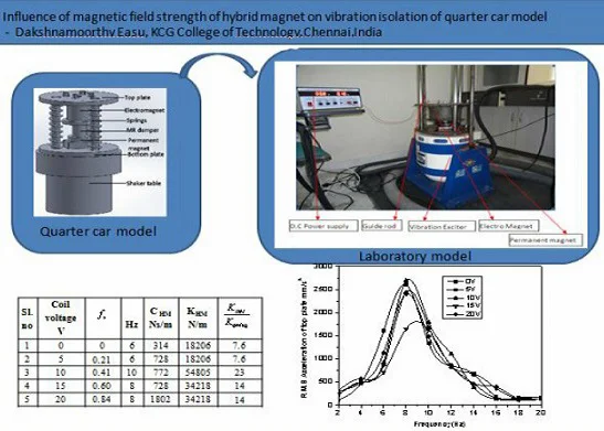
This work studies the vibration isolation of a single degree of freedom (SDOF) quarter car model under the influence of the magnetic field strength of electromagnet of a hybrid electromagnet (EM) and permanent magnet (PM) combination. Furthermore, the time history plot helps to study the influence of the relative movement of the electromagnet and the permanent magnet on the top plate, base plate, stiffness of the system and damping coefficient. A laboratory scale model of a SDOF quarter car with a hybrid magnet is tested on an open loop type shaker table at different frequencies of base excitation. Data acquisition and analysis have been carried out with the aid of two piezoelectric accelerometers and Lab VIEW software. Also, the theoretical analysis is carried out in MATLAB Simulink. From the experimental and Simulink results, it is found that the repulsive force between the electromagnet and permanent magnet varies the base and top plate amplitude, the stiffness of the system and damping coefficient of the suspension elements.
Highlights
- Variable damping and stiffness have been observed due to repulsive force between magnets
- The repulsive force between the electromagnet and permanent magnet varies the base and top plate amplitude
- The shift in the peak of frequency Vs amplitude plot was observed due to repulsive force between electromagnet and permanent magnet.
- The increase in damping and stiffness of HM SDOF quarter car model with the increase in the magnetic field of EM was observed.
- The force acting during upward and downward movements is the same in an energized HM system of the model, unlike the conventional spring mass SDOF system exhibited by non-energized HM system
1. Introduction
Generally, the suspension system of a vehicle plays a vital role to support the body weight and provide comfort by isolating the body from road-induced vibrations. A conventional suspension system which uses springs and dampers has certain limitations because of the fixed stiffness and damping coefficient of the elements. Actuators are employed in parallel or series with the conventional elements to provide better comfort, stability and vehicle handling over a wide range of vehicle speeds provided by the robust controllers. Many research works reveal the variation of the stiffness and damping coefficients of suspension elements [1-4]. Magnetorheological fluid (MRF) and Electro rheological fluid dampers are capable of varying the damping coefficient of the damper.
Similarly, for varying the stiffness, actuators of hydraulic or pneumatic or hybrid magnets are added to the conventional system. The hybrid magnet works on levitation principle which varies the damping and stiffness of the system. Such magnets in combination with conventional passive elements show promising performance. The maglev suspension considerably improved the suspension performance, reducing transmissibility around resonant frequencies and vibration of the car body [5]. Likewise, the hybrid magnet chiefly reduced the vertical displacement of the top plate of single and two degrees of freedom vibration isolation with the use of hybrid magnet was more compared to the conventional suspension system [6, 7]. In a different perspective, the vibration isolation system consisting of a standard helical coil spring and some iron (ferrite) particles layers stacked with PM and EM under disturbance cancellation control and the isolation of vibrations from the base to be almost zero [8].
Further, the response of electromagnetic actuator forces is similar to the passive suspension system within a minimal response time (>20 Hz) for eliminating road vibrations [9]. The improvement in the comfort was reported more than 40 % keeping the suspension travel within the limit and 31 % improvement in vehicle handling using the robust controller for the electromagnetic suspension system [10]. The performance of the electromagnetic actuator in the system for the bumpy road input was better than the conventional suspension system and the maximum percentage reduction in sprung mass acceleration was 62 % [11]. The variation in stiffness of the spring due to the electromagnet was proved experimentally with the use of a rotary actuator [12-15].
This work aims to investigate the effect of the magnetic field strength of hybrid on the variation in damping coefficient and stiffness of the suspension elements experimentally and the novelty is study the shift in the peak of the top plate movement at different frequencies of base excitation.
2. Experimental setup of quarter car model
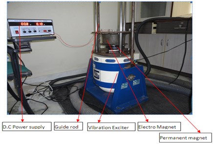
For the experimental study, a fabricated quarter-car setup of the SDOF system as a physical representation of the reduced scale model (1:25 ratio) of one-quarter of a passenger vehicle. Based on the findings from the previous works, the specifications of the quarter car model are: the mass of the top plate is 14.5 kg, a stiffness of the spring is 2380 N/m and damping coefficient of the damper is 364 Ns/m2. More importantly, the hybrid magnet which is a part of the top plate weighs 12.5 kg and it’s like poles of the EM and PM are close as shown in Fig. 1. At the central hollow part of the EM, the damper is placed. Besides, the EM is fixed on the bottom side of the top plate and the permanent magnet is kept on the base plate. Three guide rods prevent the lateral movement of the top and the base plate placed on an electrodynamics shaker (Make: Saraswathi Dynamics, India. SEV005, maximum capacity 50 kg peak SINE, frequency range1 Hz to 3000 Hz, vertical displacement 12 mm (peak to peak) and maximum acceleration 80 g (peak to peak). Moreover, the springs are designed in such a way to give a gap between the magnets. With the help of an open loop type manually controlled exciter, the base of the fabricated setup is excited in the frequency
Fig. 1Schematic representation of: a) PM, b) EM. Dimensions are in mm
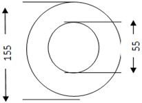
a)
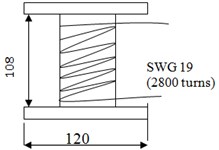
b)
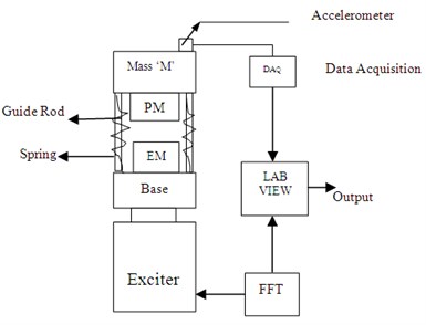
Two accelerometers (Make: PCB Piezotronics IEP (Integrated Electronic Piezoelectric) type, PCB J35B33, resolution 0.005 m/s2 range = 1-4000 Hz, sensitivity 60 mV/g) with four-channel data acquisition card acquire the base and the top plate movement. A force sensor of IEPE (Integrated electronic piezoelectric type accelerometer) senses the forces exerted on the top plate due to the hybrid magnet in addition to spring and damper. The variation of field strength with a distance of the PM and EM is measured using a Gauss meter (Make: Polychromic Corporation, Model GM-504, range 200 Gauss to 20,000 Gauss, resolution 0.1 up to 200 Gauss and 1 up to 2000 Gauss). As the standard current capacity of the electromagnetic coil is 2 A, the experiments are restricted to use of voltage up to 20 V with an interval of 5 V.
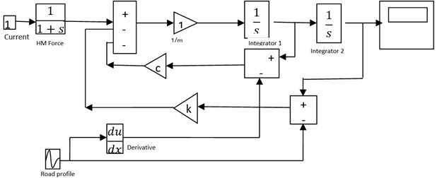
As the EM is fixed on the top plate (Chassis) of the quarter car model which is subjected to ground induced vibration and also the force applied by HM depended upon the relative displacement (-) of the top plate and current of a coil of the electromagnet. The performance of a quarter car model with HM is analyzed in MATLAB Simulink (Fig. 3). By using half power method, the damping ratio of HM is calculated from experimental data. From the plot of the frequency Vs Transmissibility ratio of HM, the two frequencies are obtained by dividing the maximum value by 1.414.
Fig. 2a) Schematic representation of a quarter car model, b) experimental setup
a)
b)
Fig. 3Block diagram of the SDOF model in MATLAB Simulink
3. Results and discussion
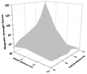
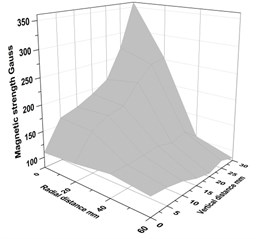
As the field strength of the PM and EM is not uniform throughout the vicinity, the variation on the top surface of the EM and PM has been noted with the help of a Hall probe Gauss meter. The variation in the magnetic field strength of the PM and EM at different locations is shown in Fig. 4 and Fig. 5. The repulsive force between the magnets varies based on the field strength. It is observed that the magnetic field strength of the EM is the maximum on the surface and decreases as the altitude from the surface increases. Also, along the radial direction, the magnitude of magnetic field strength is maximum at the outer edge of the flange of EM and its value is constant around the inner side of the flange. The repulsive force at the outer edge of both the magnets is maximum for the field strength of EM and PM.
Fig. 4a) Different locations EM where magnetic field strength was measured, b) variation of magnetic field strength on PM
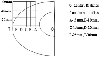
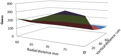
Fig. 5Variation of magnetic field strength on EM at: a) 5 V, b) 10 V
a)
b)
3.1. Influence of magnetic field strength on vertical acceleration of top plate of SDOF
Passenger comfort of the car model is quantified by the root mean square (R.M.S) acceleration of the top plate. For the analysis, the signals acquired from accelerometers with the use of DAQ card and Lab VIEW software and R.M.S values of the signals for 10 s. The magnetic field strength of EM is varied by varying the voltage supply to the coils of EM and the variation of R.M.S acceleration is shown in Fig. 6. The peak R.M.S. acceleration of the model occurs between 6 Hz and 10 Hz for all ranges of a coil voltage. These peak values correspond to the resonance of the system. The reduction in acceleration at resonance on energizing EM of the HM system in the model is compared to the non-energized EM of HM system at resonance along with conventional spring and damper.
Fig. 6R.M.S acceleration of SDOF using the hybrid magnet
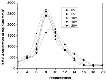
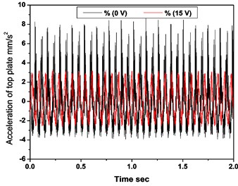
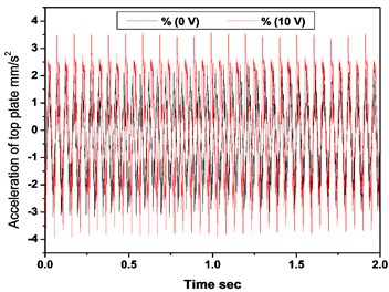
The response of the model for voltage in the range of 5 to 20 V is better at 18 Hz and 20 Hz, when compared to non-energized EM. This is due to vibration isolation of the top plate at these frequencies. At 10 Hz, 10 V and at 8 Hz, 15V, the maximum acceleration and the maximum reduction are observed respectively. These extreme cases are shown in Fig. 7 and Fig. 8(a), (b) wherein acceleration for a period of 2 s.
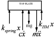
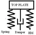
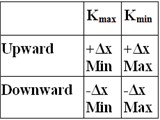
At 10 V, the magnetic field strength of the electromagnet is less when compared with a permanent magnet which results in attraction between the core of EM and PM instead of repulsion(levitation). This would be the reason to increase the stiffness of the system and consequently increases the acceleration of the top plate. Whereas, at 15 V the magnetic field strength of the EM is almost equal to the field strength of the PM which favorably levitates the top plate. The non-energized system shows greater acceleration during the upward motion than downward motion, but, when HM is energized; the acceleration during upward and downward is the same. The performance of the model is better concerning stability due to symmetric and downward motion. During the upward movement of the top plate, PM faces the resistance due to repulsive magnetic field interactions of EM and PM. During the downward movement of the top plate, the downward movement of PM is overpowered by repulsive magnetic force, if and only if, it overcomes the stiffness of the spring (Fig. 9). Thus, the stiffness due to the magnetic field also acts beside the stiffness of the spring in the SDOF using HM. As top plate is movable, based on the net effect of spring force, magnetic stiffness, damping force, weight and inertia force of the top plate, acceleration or displacement may retard to a less or more significant extent. Information on the magnitude of spring stiffness, magnetic field stiffness and damping coefficient helps in understanding the phenomena. The minimum variation in acceleration during the upward and downward motion of the model provides better passenger comfort.
Fig. 7Acceleration of top plate of the HM SDOF system, for: a) 15 V at 8 Hz, b) 10 V at 10 Hz and their comparison with non-energized EM (0 V)
a)
b)
Fig. 8SDOF quarter car model of model: a) free body diagram of top plate, b) schematic representation of top plate, c) Δx in downward and upward. KHM – stiffness of hybrid magnet, Kspring – stiffness of spring, Kmax– maximum stiffness, Kmin– minimum stiffness, Δx – expansion due to magnetic effect of virtual magnetic spring
a)
b)
c)
Fig. 9R.M.S displacement of SDOF of the model
3.2. Influence of magnetic field strength of EM on vertical displacement of top plate of SDOF
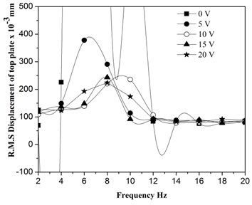
The vertical displacement of the top plate of the SDOF quarter-car model is obtained from the accelerometer data. The R.M.S. displacement of the top plate of the model increases up to a certain frequency of base excitation and decreases after that and the peak frequency increases with a coil voltage of EM is shown in Fig. 10. These peak values correspond to the resonance of the system due to vibration isolation of the top plate at these frequencies.
3.3. Influence of magnetic field strength of EM on stiffness and damping coefficient of hybrid magnet system
Theoretically, the resonance occurs at 2 Hz since the natural frequency of the system is 2 Hz. However, experimental results show the resonance of the system occurring in the frequency range of 6 Hz to 10 Hz. The probable reason is due to an error in the electrical design of the hybrid magnet [7] and stiffness arising due to magnetic field interaction. This indicates that the hybrid magnet possesses characteristic of the elastic element (spring) as well as the damping coefficient of the viscous element (damper). The resonance frequency has been increased due to an increase in stiffness of the system. i.e., the addition of the magnetic field stiffness along with spring stiffness (Pranato et al., 2007). The variation of the damping coefficient of HM for different coil voltage is shown in Table 1. The observed increase in the resonant frequency of the system with increasing voltage is due to the increase in stiffness. It is observed that the increase in resonance frequency to 6 Hz for 0 V of electromagnetic coil compared to 2 Hz of the system as natural frequency. In the absence of power supply to the electromagnet, there is a weak attractive force of PM on the non-energized electromagnet. On energization of EM with 5 V, the magnetic field strength of the electromagnet and the related repulsive force exerted on the top plate are less and hence the resonance frequency is the same as 0 V, i.e. 6 Hz.
Table 1Damping coefficient and stiffness of hybrid magnet for different coil voltage of electromagnet of model
Sl. No | Coil voltage of EM V | ×10-3mm | Hz | rad/s | viscous Ns/m | HM Ns/m | spring N/m | KHM N/m | |||
1 | 0 | 0 | 799 | 6 | 37.6 | 0.63 | 364 | 314 | 2380 | 18206 | 7.6 |
2 | 5 | 0.21 | 378 | 6 | 37.6 | 1.00 | 364 | 728 | 2380 | 18206 | 7.6 |
3 | 10 | 0.41 | 236 | 10 | 62.8 | 0.63 | 364 | 772 | 2380 | 54805 | 23 |
4 | 15 | 0.60 | 243 | 8 | 50.2 | 0.75 | 364 | 728 | 2380 | 34218 | 14 |
5 | 20 | 0.84 | 224 | 8 | 50.2 | 1.25 | 364 | 1802 | 2380 | 34218 | 14 |
– Peak amplitude of acceleration, – Damping ratio, – Resonance frequency, – damping coefficient spring – Stiffness of spring, KHM-Stiffness of HM, – the ratio of the magnetic field strength of EM and PM, – Natural frequency of the system | |||||||||||
The shift in the natural frequency of the system from 2 Hz to 10 Hz is attributed to the increase in stiffness of the system with energization of EM with 10 V. The repulsive force between EM and PM is more when compared with the supply of 5 V to the electromagnetic coil resulting in an increase of stiffness. For the supply of 15 V and 20 V to the EM, the resonance frequency () of the system is 8 Hz. Also, the resonance frequency is less than the HM system with 10 V, i.e., 10 Hz. This can be attributed to the levitation of the top plate with an increase in the magnetic field strength ratio of EM/PM above 0.41. The magnetic field plays a dual role as spring and damper as seen from the increasing value of CHM and KHM for the supply of 5 V and 10 V. As the coil voltage increases beyond 10 V the repulsive force between EM and PM favours levitation and leads to isolation of the top plate from road disturbance occurs.
4. Influence of magnetic field strength of EM on relative displacement
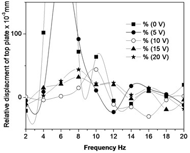
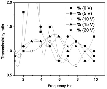
The variation of relative displacement of the model is shown in Fig. 10(a). The model showed better performance for the input of 10 V of the electromagnetic coil in the frequency range of 12 Hz to 20 Hz. At a higher frequency range, the reductions of the relative displacement in both the models follow the same pattern. The variation in the displacement of both the models is due to the nonlinear repulsive force exerted on the top plate. The force acting on the top plate is used to reduce the displacement and the net reaction force acted on the spring as the electromagnet is stationary. The transmissibility ratio of SDOF quarter car model for different coil voltage and base excitation is shown in Fig. 10(b). It is observed that the performance of the model is reasonable when compared to the non-energized system.
Fig. 10a) Relative displacement vs. the frequency of base excitation of the model, b) transmissibility ratio vs. the frequency ratio of the model
a)
b)
The transmissibility ratio of the model for the frequency ratio 1 corresponding to resonance frequency is 0.8 for non-energized HM system. This is due to attraction to the core of EM by PM. On supply of power to the electromagnetic coil, the movement of the top plate is opposed by the repulsive force between fixed PM and movable EM. At some frequency ratios, the performance of the model is better when compared with the non-energized system. At 10 V, the magnetic field strength of the EM is less when compared with a PM which results in attraction between the core of EM and PM, instead of repulsion. This could be the reason for the transmissibility ratio less than one. Whereas, at 15 V and 20 V the magnetic field strength of the EM is almost equal to the field strength of the PM which results in the increase in transmissibility ratio due to levitation of the top plate. In the model, the EM is fixed on the top plate (Chassis) of the quarter car model which is subjected to ground induced vibration and also the force applied by HM depends upon the relative displacement (-) of the top plate, and current of the coil of the electromagnet. The force acting on the top plate is nonlinear due to the non-linear relationship of the distance between EM and PM on the force as well as varying magnetic field around EM and PM. The R.M.S force acting on the top plate at all frequencies for non-energized HM (0 V) is due to conventional spring stiffness and some extent due to the attractive magnetic force of PM on EM material. The maximum net force acting on the plate at 14 Hz is 19 N.
As in the system, both EM and PM are allowed to move along the guide rods, the force transmitted to the top plate is the net force considering spring force, inertia force and the dead weight of the plate. In the case of 15 V and 20 V energization of HM, the maximum force is at 8-10 Hz and forces are higher at all frequencies compared to 5 V and 10 V. This indicated that levitation forces the top plate to move to a large displacement and supersedes the effect of conventional spring and damper. For the lower voltage of HM, along with conventional spring and damper, the system is useful for vibration suppression. As the force sensor is placed between the fixed plate and top plates, the force exerted by spring and HM is due to the relative displacement of the top and bottom plate. The following equation is used to determine the force exerted on the top plate due to spring and damper.
4.1. Theoretically calculated force
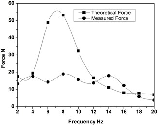
The force measured from the force sensor placed on the top plate of SDOF is compared with the value calculated from the theoretical study. Both the theoretical and measured force follows the same pattern except at 6 Hz and 8 Hz. This is due to the resonance of the SDOF system energized with 5 V. The variation in the measured and the theoretical values may be due to the friction, the phase difference between the top plate and the bottom plate. Fig. 11 shows the time history of the theoretical results of each element obtained from MATLAB Simulink with the use of calculated values of the damping coefficient from the experiment results. The base excitation is given from the experimental data and the top plate response followed by the experimental and theoretical results is the same.
Fig. 11Comparison of theoretical force and measured force for 5 V energization of HM
5. Conclusions
The objective of this work is to study the performance of the suspension system with a hybrid magnet and also the influence of the hybrid magnet on damping and stiffness of the system. A study on the vibration isolation of a quarter car model has been carried out with the use of HM. The experiment was conducted on the electrodynamic shaker with frequencies varies from 2 to 20 Hz as the real vehicle velocity is within the limit. Hybrid magnet exhibited both spring and damper characteristic as observed by the reduction in amplitude and shift in resonant frequency. The increase in damping and stiffness of HM SDOF quarter car model increased with the magnetic field of EM. In the present experimental system, 15 V energization found to exhibit better performance. The force acting during upward and downward movements is the same in an energized HM system of the model, unlike the conventional spring mass SDOF system exhibited by non-energized HM system. It is possible to achieve vibration isolation at a low frequency and a higher frequency in the range of 2-20 Hz. The experimental data can be used as an input for designing a controller to control the magnetic field strength of EM of the hybrid PM-EM combination. Other parameters of interest, maybe ratio of magnetic strength of EM and PM, stiffness ratio of conventional spring and HM and non-linear distribution of magnetic field.
References
-
Suciua Claudiu Valentin, Tobiishib Tsubasa, MouribRyouta Modeling and simulation of a vehicle suspension with variable damping versus the excitation frequency. Journal of Telecommunications and Information Technology, Vol. 1, 2012, p. 83-89.
-
Robertson W. S., Kidner M. R. F., Cazzalato Ben S., Zander Anthony C. Theoretical design parameters for a quasi-zero stiffness magnetic spring for vibration isolation. Journal of Sound and Vibration, Vol. 326, Issue 1, 2009, p. 88-103.
-
Thite A. Development of a refined quarter car model for the analysis of discomfort due to vibration. Advances in Acoustics and Vibration, Vol. 2012, 2012, p. 863061.
-
Lei Shuliang, PalazzoloAlan Control of flexible rotor systems with active magnetic bearings. Journal of Sound and Vibration, Vol. 314, 2008, p. 19-38.
-
Masao Nagai, Seiki Tanaka Study on the dynamic stability of repulsive magnetic levitation systems. JSME International Journal, Vol. 33, Issue 1, 1992, p. 102-108.
-
Kim Y. B., Hwang W. G., Kee C. D., Yi H. B. Active vibration control of a suspension system using an electromagnetic damper. Proceedings of the Institution of Mechanical Engineers, Part D: Journal of Automobile Engineering, Vol. 215, Issue 8, 2001, p. 865-873.
-
Mache A., Joshi A. Theoretical and experimental dynamic response analysis of a road vehicle suspension system using an electromagnetic damper. SAE Technical Paper 2007-01-4271, 2007, https://doi.org/10.4271/2007-01-4271.
-
Nagaya K., Hata H., Sakamoto N., Nojiri A., Murakami I. Vibration isolation system using spring actuator with iron particle layers stacked with permanent magnet and electromagnet under disturbance cancellation control. Journal of Optoelectronics and Advanced Materials, Vol. 10, Issue 5, 2008, p. 1222-1227.
-
Gysen Bart L. J., Paulides Johannes J. H., Janssen Jeroen L. G., Lomonova Elena A. Active Electromagnetic Suspension System for Improved Vehicle dynamics. IEEE Vehicle Power and Propulsion Conference (VPPC), Harbin, China, 2008.
-
Van Der Sande T. P. J., Gysen B. L. J., Besselink I. J. M., Paulides J. J. H., Lomonova E. A., Nijmeijer H. Robust control of an electromagnetic active suspension system: simulations and measurements. Mechatronics, Vol. 23, Issue 2, 2013, p. 204-212.
-
Prabu K., Jancirani J. Performance of electromagnetic based suspension system for automobiles. International Journal of Vehicle Structures and Systems, Vol. 4, Issue 2, 2012, p. 43-47.
-
Tjahjo Pranoto, Kosuke Nagaya, Yoshiaki Ebara, Quan Qi Long Vibration suppression device using permanent-electromagnet, Journal of Materials Processing Technology, Vol. 181, 2007, p. 235-240.
-
Lalitkumar Maikulal Jugulkar, Shankar Singh, Suresh Maruti Sawant Analysis of suspension with variable stiffness and variable damping force for automotive applications. Advances in Mechanical Engineering, Vol. 8, Issue 5, 2016, https://doi.org/10.1177/1687814016648638.
-
Lalitkumar Jugulkar, Shankar Singh, Suresh Sawant Mathematical modeling and experimental validation of mono-tube shock absorber. World Journal of Engineering, Vol. 13, Issue 4, 2016, p. 294-299.
-
Denhartog J. P. Mechanical Vibrations. Dover Publications Inc., New York, 1985.

