Abstract
This work displays results of a modelling-based investigation a process of multi-cutter turning process focusing on the stability of nominal steady-state case. The modelling is based on the new surface formation equations, on the equations of motion and on a rational fraction cutting law. The influence of the parameters of the system on the stability of the steady cut is analyzed.
1. Introduction
Multi-cutter turning is one of the ways to increase the productivity of turning process in manufacturing [1-5]. At certain conditions, the turning process involving constant chip thickness incurs dynamic instability [5-8, 11]. The loss of stability and the onset of auto-oscillations may be sensitive to several phenomena, such as the regenerative cutting of the surface created by the previous tool pass, ploughing caused by the flank face interaction, workpiece flexibility, temperature-induced effects [8-14]. In the case of multi-cutter turning, the deflection (vibrations) of the cutters is an important parameter.
Specific features of modeling multi-cutter turning dynamics with the regeneration-based interaction of the cutters are considered in the present work, in view of the steady state cutting stability evaluation.
2. Modeling approach
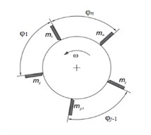
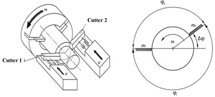
The workpiece is assumed to be a cylinder-shaped rigid body (of radius R and of length l) rotating around its longitudinal axis with angular velocity ω (Fig. 1(a)). n cutters are simultaneously engaged in turning. These cutters are disposed in a circular arrangement with angular interval φj(j=¯1,n) between neighbouring cutters, such that ∑nj=1ϕj=2π, fixed on a common carrier (Fig. 1). This carrier realizes a feed motion along the workpiece axis with a constant speed V.
Fig. 1Multi-cutter turning modeling
a)
b)
To put forward the multi-cutter-related phenomena, only the axial degrees of freedom of cutters and axial cutting force components are taken in consideration.
Each cutter (numbered by the index j) is represented as a rigid body, independently fixed on the carrier by a holder, featuring its individual stiffness and damping.
The equations, formulating the cutting-generated surfaces are bead on the following finite relations [4, 9, 15, 16]:
where Lj(t) is the axial distance from the free end of the part to the current surface under j-th cutter; Dj(t) is the axial distance from the j-th cutter edge to the surface being processed Lj-1(t-tj-1); uj(t) – axial deflection (vibration) of the j-th cutter from its nominal quasi-static location; hj(t) – uncut chip thickness for the j-th cutter; A=l-Z0 – constant distance, l – length of the cylindrical surface being turned; Z0 – initial axial position of the first cutter (nominal set value), H0j – initial axial offset of the j-th cutter (nominal set value) from the first one, axial for which A is defied, t – current time.
Cutting forces in axial direction for each cutter are accounted for by an analytical model based on a rational fraction expression [8, 11]:
with K0=γσLB apparent static stiffness, σL characteristic stress value for given material, B chip width; γ, r non-dimensional coefficients, determined experimentally for given process conditions at hand, j cutter number; c characteristic linear size of the cutting process.
Equations of motion for the vibrations of cutters in the axial direction read as follows:
with mj – mass of j-th cutter, dj and kj – damping and stiffness coefficients for j-th cutter, respectively.
Eqs. (1-3) constitutes a complete model for dynamics of the multi-cutter turning process under consideration. This system of equations is then transformed to non-dimensional form, by means of the following characteristic scales factors choice: distance scale X* – feed per turn h0, time scale – T*=√∑ni=1Ti2/n, Ti=2π√mj/kj, Ti – free oscillation period for each cutter, cutting force scale – F*=K0h0. Hence, in the case when all the cutters have identical properties (m1=m2=...=m,k1=k2=...=k,d1=d2=...=d,T1=T2=…)the Eqs. (1-3) would become:
Here the non-dimensional parameters are defined as follows:
Λj(τ)=Ljh0,Δj=Djh0,ρ=2πωT,Α=Ah0,Η0j=H0jh0.
It should be noted that the parameter 1/ρ corresponds is proportional to the cutting speed and Πj non-dimensional axial component of cutting force.
3. Stability analysis of steady-state double cutter turning process
A specific case of two cutters is considered in Fig. 1(b), when the cutters are disposed around the workpiece, defined by the angles φ1=π-Δφ and φ2=π+Δφ, thus defined by one parameter Δφ – deviation of the angle between cutters from π. In this case, the system of Eq. (4) take the following expression:
In the case of steady state cutting, the distances Δj≥0 are equal to the respective nominal cut depths, i.e. ηj=Δj≥0; j= 1, 2. Hence, from Eq. (6) it follows:
After substituting Eq. (7) into the system Eq. (6) one obtains the classic form of equations of motion:
Due to Eqs. (7-8), the steady state cut at constant thickness η0j≡ηj0=constj is possible only at constant deflection magnitudes of each of cutters: ξ0j≡ξj0=constj. Thus, the Eqs. (7-8) reduce to the following steady case:
One can define the notation:
representing tangent stiffness coefficients of the tool-workpiece interactions, acting on each cutter, and depending on the cut thickness. In particular, pj(0)=1, pj|η0j→∞=r.
Variation equations in the vicinity of unperturbed state are the following:
For fixed values {τ1,τ2,η*,r,Η}, the coefficients {p1,p2} are completely defined by Eq. (10).
The solution of the system Eq. (11) will be sought in the form δξj=Сjexp(λτ). After combining Eq. (9) and Eq. (11), one obtains:
The characteristic Eq. (12) enables, for any value of λ to determine static cutting stiffness κ as a function of ρ, i.e. the workpiece revolution period. The system under consideration would not admit static divergence instability of the steady state cut; only a dynamic bifurcation of (Poincaré – Andronov – Hopf type) is possible, leading to autooscillations. From the Eqs. (12), by putting λ=2πis and by verifying the real and imaginary parts of the equation, one obtains:
4. Results and discussion
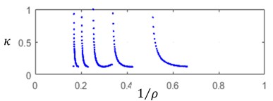
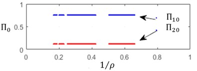
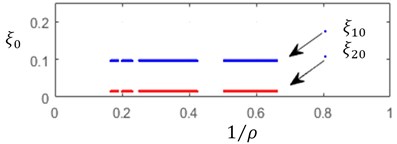
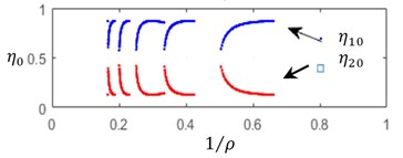
By solving the Eqs. (9, 12), one can construct, for the steady state cut process, the boundaries of the stability zones with respect to the relative static stiffness parameter κ and to the cutting speed parameter 1/ρ. On these boundaries Static deflections ξj0, as well as cutting forces Πj0 and chip thickness ηj0. Several values of delay and ratio τ1/τ2={1;2} and of relative axial position of the cutters Η={0;1} have been tested. Fig. 2 illustrates the computation results for the following data set: η*= 0.15, r= 0.65, ζ= 0.05 and τ1/τ2= 1/3, Η= 0.2.
An increase in the cutting speed parameter 1/ρ involves an observable extension the instability zones – Fig. 2(а). In the same time, cutting force and deflection magnitudes, specific for each cutter, are practically independent of the cutting speed parameter – Fig. 2(b)-2(c). A significant variation of steady state cut stiffness is takes place when the workpiece rotation rate is close to multiples of the cutter eigenvalues – Fig. 2(d). Discontinuities on these diagrams correspond to integer values of ρ.
From analogous results, obtained for different values of the delay ratio τ1/τ2={1;2} and relative axial position Η={0;1}, shows that the stability boundaries in feature only small sensitivity to these parameters, while significant variations are observed in cutting force, deflection and cut thickness magnitudes. In the case of symmetrical tool τ1/τ2=1, the presence of the initial axial shift between cuuters Η and would lead to a slight variation in the stability boundaries in the static stiffness parameter κ. In the same time the shift Η≠0, even for symmetrical cutter disposition τ1/τ2=1, leads to a differentiation in the relative stiffness and in cut stiffness.
In the case of unsymmetrical angular distribution of the cutters, i.e. τ1/τ2>1, and of even axial location Η=0, a substantial difference appears in the chip thickness values for each cutter.
Fig. 2a) Relative static stiffness parameters κ, b) cutting force Πj0, c) static deflection ξj0, d) cut thickness ηj0 as functions of 1/ρ
a)
b)
c)
d)
5. Conclusions
Based on the use the surface generation relationships, an algorithm is built for stability lobe diagram construction for the case of multi-cutter turning, taking into account arbitrary axial and angular distribution of cutters.
It is shown that in the two-cutter case, the stability boundaries of the steady state cutting process depend on the workpiece rotation rate and, for even axial positioning, do not depend on the angular distribution of cutters.
References
-
Kalidasan R., Yatin M., Sarma D. K., Senthilvelan Dixit S. An experimental study of cutting forces and temperature in multi-tool turning of grey cast iron International Journal of Machining and Machinability of Materials, Vol. 18, Issues 5-6, 2016, p. 540-551.
-
Reith M. J., Bachrathy D., Stepan G. Improving the stability of multi-cutter turning with detuned dynamics. Machining Science and Technology. Machining Science and Technology, Vol. 20, Issue 3, 2016, p. 440-459.
-
Azvar M., Budak E. Multi-dimensional modelling of chatter stability in parallel turning operation. Proceedings of the 17th International Conference on Machine Design and Production, Bursa, Turkey, 2016.
-
Guskov A., Voronov S. A., Paris H., Batzer S. A. Cylindrical workpiece turning using multiple-cutting tool. Proceedings of the Design Technical Conferences and Computers and Information Engineering Conference, Pittsburgh, Pennsylvania, 2001.
-
Kozochkin M. P. Nonlinear cutting dynamics. Russian Engineering Research, Vol. 32, Issue 4, 2012, p. 387-391.
-
Kudinov V. A. Dynamics of Machine Tools. Mashinostroenie Publishers, Moscow, 1967, p. 357, (in Russian).
-
Dombovari Z., Barton D. A. W., Wilson R. E., Stepan G. On the global dynamics of chatter in the orthogonal cutting model. International Journal of Non-Linear Mechanics, Vol. 46, 2011, p. 330-338.
-
Brissaud D., Gouskov A., Guibert N., Rech J. Influence of the ploughing effect on the dynamic behavior of the self-vibratory drilling head. CIRP Annals, Vol. 57, Issue 1, 2008, p. 385-388.
-
Gerasimenko A., Guskov M., Gouskov A., Lorong P., Panovko G. Analytical approach of turning thin-walled tubular parts. Stability analysis of regenerative chatter. Vibroengineering Procedia, Vol. 8, 2016, p. 179-184.
-
Wang, Feng C. X. Development of empirical models for surface roughness prediction in finish turning. International Journal of Advanced Manufacturing Technology, Vol. 20, Issue 5, 2002, p. 348-56.
-
Gouskov A., Gouskov M., Lorong Ph., Panovko G. Influence of the clearance face on the condition of chatter self-excitation during turning. International Journal of Machining and Machinability of Materials, Vol. 19, Issue 1, 2017, p. 17-39.
-
Benardos P. G., Mosialos S., Vosniakos G. C. Prediction of workpiece elastic deflections under cutting forces in turning. Robotics and Computer-Integrated Manufacturing, Vol. 22, 2002, p. 505-514.
-
Astashev V. K., Korendyasev G. K. Thermomechanical model of cutter self-oscillation in perpendicular free cutting. Journal of Machinery Manufacture and Reliability, Vol. 41, Issue 6, 2012, p. 435-440.
-
Kondratenko K., Gouskov A., Guskov M., Lorong Ph, Panovko G. Analysis of indirect measurement of cutting forces turning metal cylindrical shells. Vibration Engineering and Technology of Machinery, Vol. 23, 2014, p. 929-937.
-
Guskov A. M., Voronov S. A., Paris H., Batzer S. A. Nonlinear dynamics of a machining system with two interdependent delays. Communications in Nonlinear Science and Numerical Simulation, Vol. 7, Issue 3, 2002, p. 207-221.
-
Lamikiz A. Calculation of the specific cutting coefficients and geometrical aspects in sculptured surface machining. Machining Science and Technology, Vol. 9, Issue 3, 2005, p. 411-436.
Cited by
About this article
This research was supported by the Russian Foundation for Basic Research, Project No. 16-58-150001 NCNI_a and French National Center for Scientific Research, Project PRC No. 263581.

