Abstract
Aiming at the indoor location and navigation problem of humanoid biped robot with complex motion structure, a humanoid biped robot localization and navigation system based on ORB-SLAM is designed. Firstly, the working principle of ORB-SLAM is analyzed, and it is improved to realize the function of missing map reading and generating dense point cloud map. Secondly, the dense point cloud map is converted to octomap, and then the conversion of 3D map to 2D map is completed. The SBPL planning library is improved to carry out the path planning of the robot, and the path planning based on the boundary exploration is realized. Finally, the experimental verification is carried out on the biped robot to verify the effectiveness of the location and navigation system design in the indoor environment.
1. Introduction
Autonomous location and navigation in unknown environment, is one of the key problems for service-oriented robots [1]. It involves mapping, location, path planning and robot joint trajectory planning. It requires functional modules to cooperate with each other1 [2]. The history of the research on SLAM has been over 30 years, and the models for solving SLAM problems can be divided into two categories: filtering based methods and graph optimization based methods [3]. The filtering based method use EKF, UKF, PF and other filters to iterate and update the pose and posture of the feature points in the map, such as FastSLAM proposed by Michael Montemerlo et al. [4]. The method based on graph optimization using the bundle adjustment method to map the feature point and robot pose optimization and error minimization methods, including PTAM proposed by Georg Klein et al. [5], and ORB-SLAM Proposed by Raúl Mur-Artal [6].
In most of the studies, the SLAM used by humanoid robots didn't make specific optimization for the motion characteristics of humanoid robots, but rather directly carried out experiments and evaluated the results of other SLAM research methods on humanoid robots. Study of Olivier Stasse et al put the center of mass trajectory of the robot as a priori information of Calman filter in monocular SLAM [7] in HRP-2 robot to realize the real-time, closed-loop detection function of 3D SLAM [8]. Isaac Deutsch and others at the Zurich Federal Institute of science and technology applied ORB-SLAM to the location of the soccer field of the NAO humanoid robot [9], they optimize the speed of ORB-SLAM's map loading and storage, while reducing the closed-loop detection frequency of ORB-SLAM to achieve better real-time performance. Their research is mainly focused on the location of ORB-SLAM on NAO, the process of building map is not using humanoid robots, but using the same height skateboard as robot to build and initialize map for robot soccer field [10].
2. Location and navigation system structure
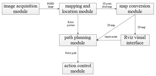
The robot navigation system is composed of image acquisition module, ORB-SLAM based mapping and location module, 2D-3D map conversion module, path planning module and robot action control module, as shown in Fig. 1.
The image acquisition module is responsible for reading RGB and depth images from the RGBD deep camera hardware, and encapsulating the image pointer in ROS, so that other ROS packets can read RGB images and deep images by listening to the message. ORB-SLAM based mapping and location module calculates the pose of the camera based on the RGB and deep images in ROS, and transforms the key frame's deep image into dense point cloud map, which is encapsulated into ROS message and broadcast for map conversion module. The map conversion module first converts the obtained point cloud map to a 3-dimensional octomap, and then converts the 2D projection based on the height. Overlooking obstacles that are higher than the height of the robot, the 2D corresponding point of the obstacle in the remaining space is marked as occupied and the 2D map is obtained.
Then the ray method is used to mark the known area and the unknown area in the 2D map based on the robot’s angle. Traversing each ray in the field of vision, we mark the space between the robot's point to the first contact point that was occupied as the known empty area. The path planning module generates a path that does not collide with obstacles through the ARA* planner in the SBPL package, enabling the robot to move from the current location to the target point. When the robot deviates from the original planning route due to its low kinematic accuracy or other reasons, the ARA* planner can make effective path replanning by using previous planning information. The robot motion control module is responsible for receiving the path generated by the path planning module, transforming the planned path into the command of the robot, and passing the instruction through the control interface of the robot, so that the robot can walk according to the given trajectory.
Fig. 1Robot location and navigation system structure
3. Mapping and location module design and implementation
There are 3 main modules in ORB-SLAM: tracking module, Local mapping module and loop closer module.
Fig. 2ORB-SLAM system block diagram
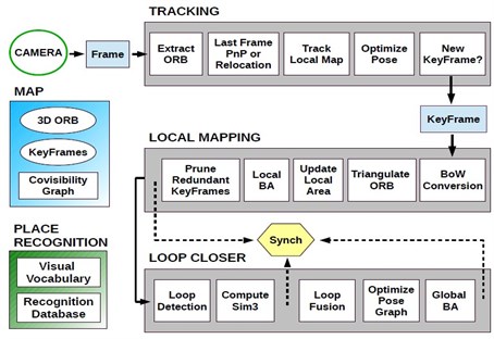
In the tracking module, images are first zoomed in eight layers of image pyramids, then the images obtained from each layer are divided into grid and ORB features are extracted. Scaling is to obtain scale invariance, and the segmentation grid is to make the feature points extracted in the picture evenly distributed. After the feature point is extracted, the position and posture of the current camera are estimated. There are three cases here, when the system has been initialized and last frame is Successful positioning, the DBOW2 library is used to match the feature points in the two consecutive frames, and the PnP algorithm is used to estimate the position of the camera. If the system is not initialized, there is no pose of the last frame. At that time, another frame image will be acquired, and the feature is extracted. The initial pose is obtained by the same method between the two frames. When the previous frame fails positioning, it is necessary to transform the current frame feature point into the image bag, and retrieve it in the image database, and find the key frame matching with the current frame, so that the pose can be calculated, and the relocation is completed.
The correction of the beam adjustment method for local maps is shown as shown in Fig. 3(a). The “Pos” represents the position of the camera, and the represents the map cloud point, and (, ) represents the two-dimensional projection of the map cloud points in different images. The red part of the graph is the position of the camera and map cloud point that participates in local optimization. After the optimization of local beam adjustment method, if more than 90 % of the map point cloud observed in a key frame can be observed by at least 3 other key frames with the same or higher resolution, the key frame will be eliminated. Eliminating redundant key frames ensures that the number of key frames will not increase indefinitely when moving in the same scene. When using the beam adjustment method to optimize the position and posture of all the key frames except the first frame, it is called the global beam adjustment method, as shown in Fig. 3(b).
Fig. 3Beam adjustment method
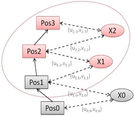
a) Local map
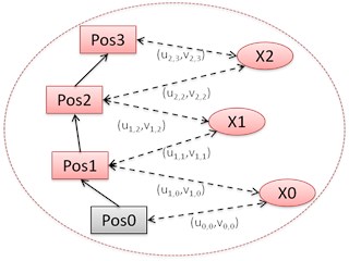
b) Global map
4. Map conversion and path planning
4.1. Construct dense point cloud map and convert to 2D map
In ORB-SLAM, the location is based on sparse cloud points map composed of feature points. Usually only a small number of feature points of objects in the environment will appear in the map. If the map is directly transformed into 2D map, the 2D map may mistakenly mark part of the object that does not extract feature points into blank, which may cause the robot to collide with these objects when robot path planning. However, by mapping the two-dimensional pixels on the depth image to the three-dimensional world coordinates through the depth image acquired by RGBD camera and the pose of the camera obtained by ORB-SLAM calculation, dense point cloud map was obtained and the problems above can be solved.
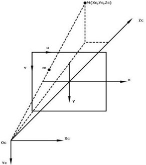
The establishment of dense point cloud maps is divided into two steps. First, for each frame, the depth image is projected to the three-dimensional space in the camera coordinate system according to the internal parameters of the camera. Then, the point cloud in the camera coordinate system is projected into the world coordinate system according to the camera position and pose of the frame, and it is fused with the global point cloud map. The process of projecting a deep image into a three-dimensional space in a camera coordinate system is shown in Fig. 6. There are two coordinate systems in the graph, namely the two-dimensional coordinate system (, ) and the camera 3D coordinate system (, , ). For a point in the depth map, the coordinates (, ) and the depth value , the projection to the camera coordinate system is (, , ).
Fig. 4Conversion of image coordinate system to camera coordinate system
The problem of the point cloud map is that it has a large consumption of memory. Octomap can store maps in the form of octree, which saves much memory space than point cloud map. Meanwhile, octomap also has excellent properties such as adjustable resolution and updating nodes in probability. The process of building octomap maps is exactly the same as that of the point cloud map. It only needs to replace the related data types of the point cloud to the octomap related type.
After the octomap map is obtained, it is projected to the - plane, and the 2D map is obtained.
4.2. Design and implementation of path planning module
The path planning module of this paper is based on the SBPL programming library, which is used to solve the shortest path on a 2D plane map. If only the obstacles and the known blank areas are marked in the 2D map, the different evaluation functions are not given to the known blank areas. This may make the shortest path of the path planning very close to the obstacle, and a little deviation from the robot can lead to a collision with the obstacle. Although modifying the robot radius could be used to alleviate this problem, but if the occupying radius of the robot was blindly modified to a large value, that may make robots unable to go through some reachable areas. In order to solve this problem, this paper adds a proper cost to the known empty area near the obstacles on the map, so that the path planning module can keep the distance between the path and the obstacle. The cost labeling algorithm can set the walking cost which is inversely proportional to the distance of obstacles in the range of obstacle radius , so that the path planning module can design a reasonable path to prevent collisions caused by robot walking deviation.
5. Experimental implementation
The experiment adopted the Darwin OP robot designed and produced by Korea Robotics company as a hardware platform. It has 20 degrees of freedom (leg 6DOF*2, arm 3DOF*2, head 2DOF), the height is 45 cm, the weight is 2.9 kg. It also equips the SR300 RGB-D camera produced by Intel, which uses structural light to obtain depth information, and the recognition depth is from 0.2 m to 1.5 m. In the experiment, the resolution of both the depth image and the color image is 640×480, and the frame rate is 60 fps. The computing platform uses the UpBoard development board of the Aaeon Europe company,based on Intel Atom x5-Z8350, with 4GB RAM. The operating system is Ubuntu14.04, and the ROS version is ROS Indigo.
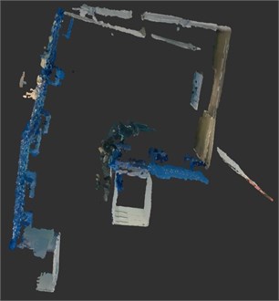
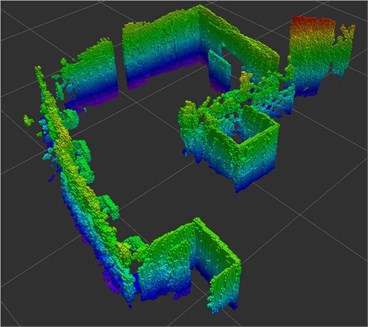
First the mapping and location module is tested, by remote control the robot to build map of a specific scene in the laboratory environment. The size of the scene is about 7 m2, and the layout is G type. The resulting point cloud map and cotomap map is shown below, the resolution of octomap is 1 cm.
Fig. 5Point cloud map and cotomap map
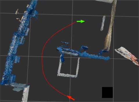
On this basis, the path planning module is tested. The output of the path planning module is shown below. The red arrow is the current pose of the robot obtained from the mapping and location module, the green arrow is the target point set by operator, and the red curve is the path generated by the path planning module. The path given by the path planning module avoids obstacles very well, and it can repaln the path in real time according to the robot pose. and achieve the desired effect. The path planning has achieved desired effect.
Fig. 6Experimental results of path planning
6. Conclusions
In this paper, ORB-SLAM was improved based on the characteristics of the humanoid biped robot. The preservation and reloading of the map are realized by serialization and anti serialization. The point cloud map and octomap are created and spliced on the basis of the key frame depth information and position posture, and the off-line creation function of dense point cloud map is realized. Integrate the position and posture information of the camera calculated by ORB-SLAM to the ROS, encapsulated into the PoseWithCovarianceStamped message in ROS. Using the Octomap_Server packet in ROS, the spliced Octomap is projected into a two-dimensional map, and the conversion of the 3D map to the 2D map is completed, and the know area and unknow region are marked in the 2D map. The cost function is added to the area near the map obstacle to prevent the collision between the robot and the obstacle. The boundary of the known area and the unknown area in the 2D map is calibrated, and the depth first search is carried out on the boundary, so as to complete the construction of the unknown indoor environment. All the sub modules is integrated and debugged and tested on the Darwin OP robot to evaluate its autonomous navigation mapping precision for the unknown environment.
References
-
Hornung A., Oßwald S., Maier D., Bennewitz M. Monte Carlo localization for humanoid robot navigation in complex indoor environments. International Journal of Humanoid Robotics, Vol. 11, Issue 2, 2014, p. 1441002.
-
Kohlbrecher S., Von Stryk O., Meyer J., Klingauf U. A flexible and scalable slam system with full 3d motion estimation. IEEE International Symposium on Safety, Security, and Rescue Robotics, 2011, p. 155-160.
-
Strasdat H., Montiel J. M., Davison A. J. Visual SLAM: why filter? Image and Vision Computing, Vol. 30, Issue 2, 2012, p. 65-77.
-
Montemerlo M., Thrun S., Koller D., Wegbreit B. FastSLAM: A factored solution to the simultaneous localization and mapping problem. Proceeding 18th National Conference on Artificial Intelligence, 2002, p. 593-598.
-
Klein G., Murray D. Parallel tracking and mapping for small AR workspaces. 6th IEEE and ACM International Symposium on Mixed and Augmented Reality, 2007, p. 225-234.
-
Mur-Artal R., Montiel J. M. M., Tardos J. D. ORB-SLAM: a versatile and accurate monocular SLAM system. IEEE Transactions on Robotics, Vol. 31, Issue 5, 2015, p. 1147-1163.
-
Stasse O., Davison A. J., Sellaouti R., Yokoi K. Real-time 3d slam for humanoid robot considering pattern generator information. IEEE/RSJ International Conference on Intelligent Robots and Systems, 2006, p. 348-355.
-
Seder M., Petrovic I. Dynamic window based approach to mobile robot motion control in the presence of moving obstacles. IEEE International Conference on Robotics and Automation, 2007, p. 1986-1991.
-
Hong W., Tian Y., Zhou C. The piecewise Monte Carlo localization system for a humanoid soccer robot. IEEE International Conference on Automation and Logistics, 2009, p. 1905-1910.
-
Likhachev M., Gordon G. J., Thrun S. ARA*: Anytime A* with provable bounds on sub-optimality. Advances in Neural Information Processing Systems, 2003, p. 767-774.
