Abstract
This paper applies damping effect to turning and milling processes in order to enhance their chatter stability while they are in operation. The processes dynamic models and their analytical solutions were presented in detail. The models of the two processes were separately used in MatLab/Simulink with the aid of data from actual cutting tests in order to predict the processes dynamic stability. The developed model and its analytical solution for milling process have been verified by actual milling test. Then the generated stability lobe diagrams with/without damping were compared for each process. The results show that the stable cutting zone is remarkably increased for the employed low cutting speeds. The simulation and experimental results of the damped milling process are consistent. In general, this simulation approach can have practical interest especially in machining of high performance aeronautical hard-to-cut materials.
1. Introduction
Machining chatter is often caused by the self-excited vibration that occurs during the cutting action. This affects the cutting efficiency in such way that the machined part surface finish and dimensions accuracy is lowered. In addition, it damages the cutting tool and the machine, and consequently results in increasing the production cost [1]. Generally, turning and milling operations are widely used for producing a variety of components. Therefore, studying and solving the issue of chatter during turning and milling operations is highly required in order to improve their cutting performance. This is usually done by employing different simulation and analyzing techniques to predict the better cutting action of the machine tools.
One of the common methods to predict the stability of a given cutting operation is by using the lobe diagram, which employs dynamic modeling to analyze the chatter stability [2-4]. In general, this method can assist in obtaining a proper solution for high-efficiency chatter free cutting operations. However, at low cutting speeds and due to the stability of leaf blade density, the synergistic effect of choosing the cutting parameters within the stability domain vanishes. This is because the existing models do not consider the action of process damping.
In this regard, we intended to create damping effect during turning and milling operations by increasing the steady cutting zone when the machining operations are performed at low cutting speeds. Thus, the change in the cutting speed that would be caused by the friction between tool flank and uneven workpiece surface will impart damping effect on the machining process [5-7]. This may have practical interest especially when hard to cut materials are intended to be machined at low cutting speeds since machining at high cutting speeds causes severe tool wear. Therefore, the vibration damping of machine tools have attracted the attention of many researchers and become the trend towards vibration free machine tools. This includes studying of damping mechanism [8, 9], modeling of damping [10-12], stability analysis of damping [13-15] and etc. In this paper, the effect of damping technique on the chatter stability of a single degree of freedom turning and two degrees of freedom milling processes are modeled and simulated by Matlab/Simulink. Then the simulation results with/without damping are compared.
2. Modeling of the damped cutting processes
Building up and analyzing of the dynamic models for both processes is essential. Thus, the damping effect on reducing the machining processes chatter is considered. The detailed steps for obtaining an expression for cutting depth are demonstrated. The analysis based on a single degree of freedom turning process and two degrees of freedom milling process.
2.1. Model analysis of turning process
The dynamic equation of a single degree of freedom damped turning system can be described as follows:
where: m, c, k are system mass, damping viscosity, and stiffness respectively, y(t) is the amount of vibration in the Y direction, Ff is the feed force and Fp is the damping force. The process damping force, Fp, can be expressed as a function of velocity, v, chip width, cutting speed, and a constant c [16]. See Eq. (2):
where: C is the damping coefficient. By substituting Eq. (2) into Eq. (1), the dynamic equation of the damped turning process can be obtained as follows:
Hence, the frequency response function of the system in the Y direction can be written in the following way:
To describe the stability algorithm, consider a single degree of freedom turning operation with regenerative chatter [17]. Thus, the limiting stable chip width, blim, for regenerative chatter can be determined using the following equation:
where: Φ(ω) is the oriented frequency response function, Kf is the cutting force coefficient in the feed direction, and Re is the real part function.
The relationship between the spindle speed, Ω, and the valid chatter frequencies, fc (i.e., those frequencies where the real part of Φ(ω) is negative) are given by the follwing expression:
where S= 0, 1, 2,… is the integer number of waves per revolution (i.e., the lobe number), and ε=2π-2arctanRe(Φ(ω))ImΦ(ω), (rad) is the phase between the current vibration and the previous pass, Re(Φ(ω)), Im(Φ(ω)) are the real and imaginary parts of the oriented transfer function.
2.2. Model analysis of milling process
The dynamic equation of the two degrees of freedom damped milling system can be expressed as:
where q is the response of the system under the action of force F, and M, C, K is the system mass, damping viscosity, and stiffness respectively. Eq. (7) can be written in the matrix form as follows:
In addition, the frequency response function G(ω) of the system can be expressed as follows:
The harmonic response (q) at the critical chatter frequency (ωc) is given as follows:
The dynamic cutting force in milling process can be expressed as follows:
where: ap is the axial cut depth, Kt is the tangential force coefficient, Ceq is the equivalent damping, A0 and B0 are zero order harmonics, respectively, and are related to the radial force coefficient and the friction factor respectively [10]. The milling force F in an exponential form can be expressed as follows:
Thus, we can be obtained a simultaneous solution for the Eqs. (10) and (13) as follows:
where Λ is the eigen value of the characteristic solution of the dynamic milling equations at the frequency domain, and can be expressed as follows:
Take Λ=ΛR+iΛI and e-ωcT=cos(ωcT)-isin(ωcT), and substitute these values in Eq. (15) to obtain an expression for the critical axial cutting depth (ap) as follows:
Since the axial depth of cut is real, the imaginary part of Eq. (16) is equal to zero, ⋀I(1-cos(ωcT))+⋀Rsin(ωcT)=0. Hence, the relation between the imaginary characteristic value and real characteristic value of the solution can be written as follows:
By substitution Eq. (17) into Eq. (16), the critical axial cutting depth can be expressed as follows:
The phase angle between the internal and external modulation (ε), is given as function of the characteristic values of phase shift Ψ=arctan(s) and critical limit cutting depth in the following formula:
The spindle speed is expressed as follows:
where: ωc is critical chatter frequency and S is an integer number of vibration waves.
3. Simulation of the processes stability
The developed mathematical models and the experimental data are used by Matlab/Simulink software to predict the dynamic stability of the two processes in question. The steps followed to simulate each process are explained in the following subsections.
3.1. Turning process
Based on the above principle, a simulation program of turning stability considering the influence of process damping is developed by Matlab, and the flow chart is shown in Fig. 2.
In order to study the influence of damping process on cutting stability, a simulation is carried out to analyze the process with/without damping. the experimental data of machining with the titanium Nitride cutting tool are given in Table 1.
Table 1Parameters of titanium nitride cutter used in the simulation of turning machine
No | Parameter | Values | Unit |
1 | Overhang length | 90 | mm |
2 | Workpiece made | 1018 | steel |
3 | Diameter D | 35 | mm |
4 | Mass of the system M | 0.567 | kg |
5 | Damping coefficient C | 160 | N.s/m |
6 | Stiffness K | 9.48×10⁶ | N/m |
7 | Cutting force coefficient Kf | 2.927×10⁹ | N/m2 |
8 | Process damping coefficient C | 6.11×10⁵ | N/m |
According to the simulation results, the cutting stability was tested for the process with/without damping (Fig. 2). It can be noticed that the process with damping effect gains more stability at low cutting speeds than without damping. Thus, at spindle speed lower than 4000 rev/min, the process stability with damping effect is much better at larger cutting depth (Fig. 2(b)). In this case, the estimated axial cutting depth is higher compared to the that obtained for the process without damping (Fig. 2(a)). This indicates that turning process with damping effect has improved the process stability when machining at low cutting speed as well as participated in increasing the material removable rate.
Fig. 1Flow chart of stability for turning operation considering the effect of process damping
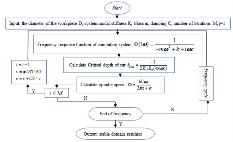
Fig. 2Effect of the process with/without damping on the chatter stability of the turning process
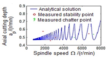
a) Process damping effects are not considered
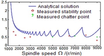
b) Consider process damping effects
3.2. Milling process
A similar procedure is used for simulating the milling process with/without damping. This is also achieved by making use of the data from actual milling test (Table 2), and the developed mathematical models in Matlab/Simulink software. Therefore, milling process with and without damping is simulated. Fig. 4 shows the simulation follow chart for the process with damping effect. In addition, the results from the simulation are verified by the actual experimental test where the frequency response function of the machine tool system is processed using the CutPro software. The spindle speed is set varied from 1000-3800 rev/min at 500 rev/min increments. The cutting starts at a minimum axial depth of 0.5 mm with 0.5 mm increments until chatter occurs. Fig. 5 shows the experimental setup of the damping milling process.
Fig. 3The setup of the damped milling process test
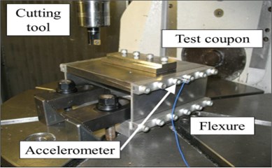
Table 2Parameters used in test of chatter stability verification in milling machine FIDIA K197
No | Parameter | Values | unit |
1 | Cutter tooth number N | 3 | |
2 | Diameter D | 18 | mm |
3 | Wear width W | 0.04 | mm |
4 | Start immersion angle ϕst | 0° | |
5 | Exit immersion angle ϕex | 90° | |
6 | Stiffness K | 9×10⁶ | N/m |
7 | Damping ratio ζ | 0.03 | N/m |
8 | Natural frequency fn | 900 | Hz |
9 | Cutting force coefficient Kf | 2×10⁹ | N/m2 |
10 | Process damping coefficient C | 2×10⁴ | N/m |
11 | Spindle speed range | 1000-3800 | r/min |
Fig. 4Flow chart of stability for milling process considering the effect of process damping
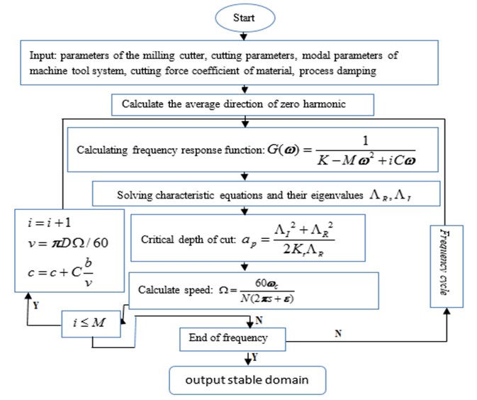
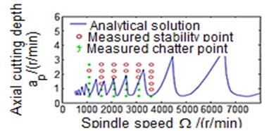
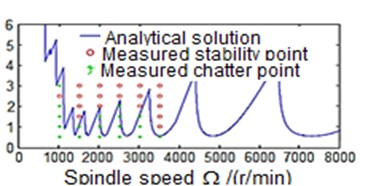
Fig. 5 reveals the stability levels of the milling process with/without damping. It can be noticed that the simulated process with damping shows higher machining stability at cutting depth slightly greater than 3 mm when the operating speed is below 2000 rev/min (Fig. 5(b)). This result is consistent with that obtained from experimental test where the machine stability for the above-mentioned speed occurs at cutting depth of almost 3 mm. Conversely, in the case of the undamped milling process, the machining stability is obtained when the operating speed is below 2000 rev/min at cutting depth less than 3 mm (Fig. 5(a)). Thus, the process with damping allows the removable rate to be increased, and at the same time keeps the machining process stable. This will have a good impact on the quality of the machined parts surface finish, and preserves the cutting tool life.
Fig. 5Effect of the process with/without damping on the stability of the milling process
a) Process damping effects are not considered
b) Consider the influence of process damping
4. Conclusions
Process damping is important for hard-to-machine materials, such as titanium, nickel based super alloys, hardened steels, etc. In these instances, the excessive tool wear does not allow high surface speeds to be used. This limits the spindle speed to low values, which in turn decreases the material removal rate. However, by exploiting process damping, higher axial cutting depth can be achieved at low cutting speed with a good degree of machining stability. Indeed, this leads to increase the material removal rates.
This paper provides a simulated and analytical solution for improving the chatter stability of the turning and milling processes by employing damping effect. The corresponding simulation program for each process is developed by using Matlab. The simulation and the cutting experiment verify the correctness of the model. Large steady cutting zone for both processes with good machining stability is obtained at low cutting speeds and consequently increases the metal removable rate. These findings may have practical interest when machining titanium and nickel based super alloys or hardened steels.
References
-
Yusuf Altintas Manufacturing Automation: Metal Cutting Mechanics, Machine Tool Vibrations, and CNC Design. 2nd Edition, Cambridge University Press, 2012, p. 119-139.
-
Li Zhongqun Z. F., And, Dong Yafeng, Xia Lei, Peng Yuerong Modeling and Simulation of cutting stability considering process damping. Journal of Hunan University of Technology, Vol. 28, Issue 6, 2014, p. 23-26.
-
Tlusty J., Zaton W., Ismail F. Stability lobes in milling. CIRP Annals – Manufacturing Technology, Vol. 32, Issue 1, 1983, p. 309-313.
-
Altintacs Y., Budak E. Analytical prediction of stability lobes in milling. CIRP Annals – Manufacturing Technology, Vol. 44, Issue 1, 1995, p. 357-362.
-
Das M. K., Tobias S. A. The relation between the static and the dynamic cutting of metals. International Journal of Machine Tool Design and Research, Vol. 7, Issue 2, 1967, p. 63-89.
-
Altintas Y., Weck M. Chatter stability of metal cutting and grinding. CIRP Annals – Manufacturing Technology, Vol. 53, Issue 2, 2004, p. 619-642.
-
Sisson R. L., Timothy Raymond, Kegg An explanation of low-speed chatter effects. Journal of Engineering for Industry, Vol. 91, Issue 4, 1969, p. 951-958.
-
Wallace P. W., Andrew C. Machining forces: some effects of tool vibration. Journal of Mechanical Engineering Science, Vol. 7, Issue 2, 1965, p. 152-162.
-
Tlusty J. Analysis of the state of research in cutting dynamics. CIRP Annals – Manufacturing Technology, Vol. 27, Issue 2, 1978, p. 583-589.
-
Ahmadi K., Ismail F. Analytical stability lobes including nonlinear process damping effect on machining chatter. International Journal of Machine Tools and Manufacture, Vol. 51, Issue 4, 2011, p. 296-308.
-
Altintas Y., Montgomery D. Mechanism of cutting force and surface generation in dynamic milling. Journal of Engineering for Industry, Vol. 113, Issue 2, 1991, p. 160-168.
-
Budak E., Tunc L. T. Identification and modeling of process damping in turning and milling using a new approach. CIRP Annals – Manufacturing Technology, Vol. 59, Issue 1, 2010, p. 403-408.
-
Ahmadi K., Ismail F. Experimental investigation of process damping nonlinearity in machining chatter. International Journal of Machine Tools and Manufacture, Vol. 50, Issue 11, 2010, p. 1006-1014.
-
Tyler C. T., Schmitz T. L. Analytical process damping stability prediction. Journal of Manufacturing Processes, Vol. 15, Issue 1, 2013, p. 69-76.
-
Ahmadi K., Ismail F. Stability lobes in milling including process damping and utilizing multi-frequency and semi-discretization methods. International Journal of Machine Tools and Manufacture, Vol. 54, 2012, p. 46-54.
-
Altintas Y., Eynian M., Onozuka H. Identification of dynamic cutting force coefficients and chatter stability with process damping. CIRP Annals – Manufacturing Technology, Vol. 57, Issue 1, 2008, p. 371-374.
-
Tlusty J. A review of: Manufacturing processes and equipment. IIE Transactions, Prentice Hall Upper Saddle River, NJ, Vol. 34, Issue 7, 2002, p. 647-648.
About this article
This paper is funded by the International Exchange Program of Harbin Engineering University for Innovation-oriented Talented Cultivation.

