Abstract
To aim at the defects of the traditional VSG (virtual synchronous generator) control schemes to only complete the primary frequency regulation equivalent to droop control, and not to realize the secondary frequency regulation, this paper proposes a new control scheme to realize the secondary frequency regulation of the VSG, such that system frequency can return to the rated value. In this method, the torque change process of the rotor of synchronous generator is firstly analyzed when the system active power fluctuates. And then, a novel secondary frequency regulation control strategy of the VSG is proposed, where the small-signal model of power transmission of the VSG is established and transfer function is analyzed, and parameters design and stability analysis of the control system are conducted. Finally, simulation experiments show the correctness and effectiveness of the proposed method.
1. Introduction
With the emergence of a series of environmental, ecological, and social sustainable issues, all sorts of renewable energies have already been widely explored and utilized, such as photovoltaic power station, wind energy, and small-type hydroelectric generation, and etc., and the permeability of which is increased quickly. However, due to a variety of DGs (distributed generations) with outputs being uncertain, unpredictable, and uncontrollable, the consumption on them has already become a major problem [1, 2]. Hence, to promote the local consumption of renewable energy, some scholars put forward the microgrid concept organically integrating all kinds of renewable energies, ESSs (energy storage systems), power converters, and loads to smooth the power fluctuations [3]. Nowadays, the voltage level of microgrid has already covered 400 V, 10 kV, and 35 kV in the medium and low voltage distribution networks in China. As a microgrid runs in an islanded mode, the DGs and the ESSs can instantaneously supply larger power support [4].
Compared with SG (synchronous generator), the grid-connected inverter possesses fast response and little inertia under conventional control strategies such as P/Q, V/f and droop control, such that it cannot effectively provide power support and maintain the frequency stability for microgrid [5]. Hence, to make it possess the characteristics of inertia and damping like SG, some scholars proposed the concept of the VSG in [6]. Today, the widely used VSG control scheme is based on the second-order model proposed in 2009 [7], which simulates the characteristics of rotor inertia, damping, and electromagnetic of SG, comprehensively, and is beneficial for the improvement of system stability. However, the scheme only can provide limited inertia support for microgrid to realize the PFR (primary frequency regulation) of the system, and fail to SFR (secondary frequency regulation), which limited its further application [8].
To improve power quality and anti-interference ability of the microgrid, there is necessary to realize SFR by controlling the DGs [9]. Centralized SFR depends on the system information to timely compute the power shortage by means of energy management system of microgrid, and the dispatch instruction require to be sent to each DG with a complex communication system, which may lead to a certain delay, and poor reliability and instantaneity [9, 10]. Distributed SFR based on conformance algorithm utilizes the information of local generation units and adjacent DGs to realize parallel operation of multiple inverters, but there are still shortcomings of communication delay, inferior reliability, and etc. [11]. Decentralized SFR only utilizes local information, has received extensive attention because of its high reliability, low cost and good expansibility [12-14]. As is presented in [15], to add integrator in the damping part of the VSG control algorithm would complete the attenuation of frequency disturbance components, but it did not realize the essence of the SFR is to adjust the input mechanical torque. By changing the droop coefficient of inverters, a fixed value online tuning method is put forward in [16]. Although without communication system, it has a large amount of computation and requires better processor.
In this paper, the traditional VSG control scheme is improved to realize the SFR of the microgrid. Based on the analysis of torque-speed characteristic of rotor, the virtual mechanical torque part of the VSG is adjusted without error according to the system frequency. Then, the parameters design and stability analysis of the control system are also carried out according to the derived small-signal model. Finally, simulation results verify the effectiveness and effectiveness of the proposed method.
2. Basic VSG control scheme
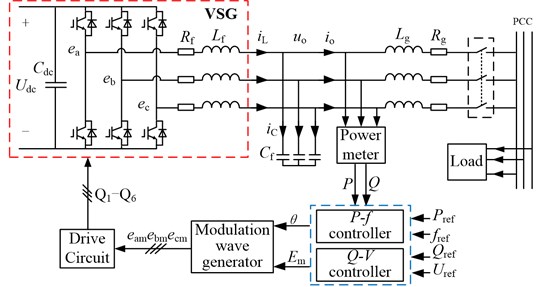
Fig. 1 shows the main circuit topology structure of the VSG with a DG, wherein the primary source of the DG could be photovoltaic panels, wind power generator, or other distributed energy resources with ESS, which can maintain the output power controlled and the voltage of DC bus stable [17]. The main circuit in Fig. 1 may be a three-phase voltage source inverter, and Q1 to Q6 represents the driving pulse, and Udc is the DC bus voltage, where LC filter is adopted to filter the harmonics of the switching frequency and its adjacent frequency band. Rg and Lg present the line resistance and reactance from VSG to PCC (point of common coupling), respectively, Em is the RMS (root-mean-square) value of modulation wave, and eam, ebm, and ecm are three-phase modulated wave signals, P and Q respectively are the instantaneous active power and reactive power whereas Pref and Qref are the references at the stable state, fref and Uref are the given reference of frequency and voltage, respectively. In addition, compared the main circuit of grid-connected inverter with the electromagnetic part of SG, the bridge-side fundamental voltage ea, eb, and ec can be regarded as exciting electromotive force, Rf and Lf are regarded as resistance and synchronous inductance of armature winding, uo and io are regarded as output voltage and current of SG terminal. To make the control system response faster, the dashed part is selected to be equivalent to the main circuit of VSG in Fig. 1 [18].
Fig. 1Main circuit topology of the VSG
2.1. P-f controller
Fig. 2 shows the block diagram of the VSG control system, including P-f controller and Q-V droop controller. The upper part represents the P-f controller being the core of swing equation, where S1, S2 are the secondary frequency control enabled switches, ki1 and ki2 are the integral coefficients of the governing loop of virtual mechanical part and damping part. In this paper, the frequency response capability of the VSG is specially focused when the active load fluctuates in microgrid, such that the second-order model of SG is adopted, and swing equation can be described as Eq. (1):
where J presents the moment of inertia of all the parts rotating of the rotor, and Tm is the mechanical torque, and Te is the electromagnetic toque, and Td is the damping torque, and D is a damping factor. As magnetic pole pair is one, the mechanical angular velocity is equal to its electrical angular frequency ωr, and the angular displacement θ is the integral of ωr. Below the mechanical torque change process of SG is analyzed in the dynamic process.
Fig. 2Block diagram of VSG control system
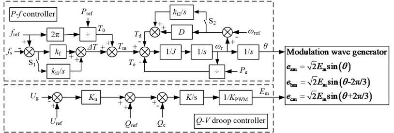
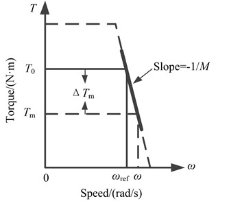
Tm consists of two parts: T0 and ΔTm, wherein T0 indicates the mechanical torque of the prime mover in stable state, and ΔTm is the response torque of frequency deviation on the rotor. In a regulated SG, the torque-speed characteristic of the rotor possesses a drop performance, that is, with the increase of the load, the rotor speed will decrease, and the torque on the rotor will increase accordingly. This can be described as Eq. (2):
where M is the speed regulation rate whose typical value 5 %. Fig. 3 shows the torque-speed characteristic of the rotor.
For a SG, when oscillation occurs, the damping torque can be induced into its damping windings such that power oscillation will be suppressed. The reference frequency of the damping windings is the synchronous angular one, i.e., ωref=ωs. Therefore, when the system is at an active power-frequency equilibrium point, the damping windings are not working.
In order to avoid the attenuated oscillation of SG rotor, we select ωref=ωN= 314 rad/s, thus, we have:
From Eq. (3), we can see that the output characteristic of VSG is of drooping like SG. As S1 and S2 are not closed, the p-f controller simulates the PFR characteristic of SG, so that there is a certain deviation between the system frequency and the rated reference value. In order to resolve the issue and realize the SFR, the Tm of the VSG would be adjusted so that system frequency could restore to rated value.
Fig. 3Torque-speed characteristic of the rotor
2.2. Q-V droop controller
Q-V droop controller is shown in the lower dashed block in Fig. 2, from it we have:
where KPWM is the transfer function from the modulator to inverter bridge, and K is the integral coefficient. Qref and Qe are respectively the reference and instantaneous value of reactive power of the inverter, and Ku is voltage-reactive power droop coefficient. Considering the influence of the filter and line impedances on output voltage, the voltage feedback of PCC is adopted, Ug and Uref are respectively the RMS value of the actual and reference value at PCC whereas Em is modulation wave’s RMS value.
Combining Em and θ that come from the p-f Controller and Q-V droop controller respectively, the three-phase modulation wave eam, ebm and ecm can be expressed as Eq. (5):
In Eq. (5), θ=∫ωrdt, KPWM=Udc/Utri, Utri is the peak value of triangular carrier.
3. SFR control strategy of the VSG
3.1. Small-signal modeling of the VSG
VSG runs in droop control mode when S1 and S2 are disconnected, and the PFR can be realized. Compared with the traditional droop control, VSG benefits from the introduction of virtual inertia and damping link, such that it possesses the ability of damping power oscillation to make frequency change process gentler, which can improve the frequency stability.
As S1 and S2 closed, VSG runs in the SFR mode. The SFR can be achieved by bringing two integrators in the virtual mechanical and damping torque part in the p-f controller, and thus the frequency deviation would be fully eliminated. The parameters design of the two PI controllers will be described as follows.
Fig. 4 is the equivalent circuit of an islanded microgrid, where the inverter is regarded as a voltage resource, and the transformer is assumed to be no phase shift action, and the impedance of inverter output, LC filter, transformer, and transmission lines are represented by Z=R+jX of the ICI (integrated circuit impedance). Let the voltage of PCC be reference, i.e., Ug∠ 0°, and thus the terminal voltage of the VSG can be expressed by E∠φ. The three-phase active and reactive power of the inverter power supply injects into PCC can be obtained by:
where φ is the phase angle of the terminal voltage, and also called as power angle error.
Fig. 4Equivalent circuit of an islanded microgrid

Under steady-state operation state, a small-signal model of power transmission is firstly derived from Fig. 2 and 4 to analyze the impact of load fluctuations on the output of the VSG. The fluctuations of frequency and voltage of the system will result in a small change on the phase and amplitude of PCC and the output voltage of the VSG, simultaneously. By analyzing the change of three-phase active and reactive power that the VSG injects into PCC after microgrid suffers a small disturbance, we then have:
For a microgrid, DG and load are connected by the transformer and transmission lines, such that it can be assumed that the resistance in ICI can be ignored. In order to make the VSG run stably and unlikely to out of step, φ is generally very small, and so we have:
Thus, Eq. (7) can be rewritten as Eq. (9):
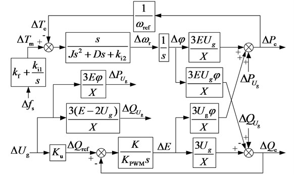
Let ΔPUg=3EφXΔUg and ΔQUg=3(E-2Ug)XΔUg, and combining them with Eqs. (1)-(2) and (4), a small signal model of the VSG can be immediately obtained as shown in Fig. 5.
Fig. 5Small-signal model of the VSG
3.2. Parameters design of the controllers
As demonstrated in [19], when the inductive in ICI is larger, there is 2 % coupling between p-f control loop and Q-V droop control loop only, such that the coupling effect can be neglected, and the decoupled small-signal model is shown in Fig. 6(a) and (b).
Fig. 6Decoupled small-signal model: a) p-f control loop, b) Q-V droop control loop

a)

b)
From Fig. 6, we can obtain the open-loop transfer function from Δfs to ΔPe and ΔUg to ΔQe respectively expressed as Eqs. (10), (11):
This paper focuses on the influence of the introduction of the gain factor of the integrators on the control system. First, the calculation method of the gain factors of the integrators is derived.
As in Eq. (1), the adjustment of the mechanical and damping torque is consistent, that is, the adjustments of both of them exist or disappear at the same time, so that ki2 can be designed firstly.
When the integrator of damping torque part is not introduced, the open-loop transfer function from ΔTm to ΔTe can be derived by:
Thus, its closed-loop transfer function can be expressed by:
According to Fig. 6, when the integrator of damping torque part is introduced, the open-loop transfer function from ΔTm to ΔTe can be derived as:
Thus, its closed-loop transfer function can be expressed by:
According to Eqs. (12)-(15), the torque regulation part is a second-order system, and the natural frequency and damping coefficient of the second-order system can be derived as Eq. (16):
According to the relation between the damping ratio and the natural frequency of the second-order system, ki2 can be obtained by:
That finishes the calculation method of the two gain factors of the integrators.
Then, the influence of the introduction of the gain factors of the integrators on the stability and the dynamic response of the system are investigated.
According to the torque-speed characteristic of the rotor shown in Fig. 3, the frequency adjustment coefficient can be obtained by kf=2π/M= 40π. In this paper, the virtual inertia J is taken as 0.2 kg·m2 refer to [20], and other parameters are designed using the proposed method in [19].
According to national grid code [21], by the change of 100 % active power corresponding to the change of 5 % grid frequency in a small-capacity power system, whereas the change of 100 % reactive power for the one of 7 % grid nominal voltage according to [22]. In this paper, it is assumed that the VSG capacity is given by 20 kVA. Considering that it needs to provide both active and reactive power support simultaneously, we have:
Ku=ΔQmax2√2ΔUmax=20×103√2×220×2×7%=459.16A.
The parameters of the three-phase VSG control system are listed in Table 1.
Table 1Parameters of the VSG
Parameters | Value | Parameters | Value | Parameters | Value |
Rf | 0.002 Ω | Rg | 0.05 Ω | φ | 0.1 rad |
Lf | 3 mH | Lg | 8 mH | Ug | 220 V |
Cf | 500 μF | E | 225 V | K | 0.141 |
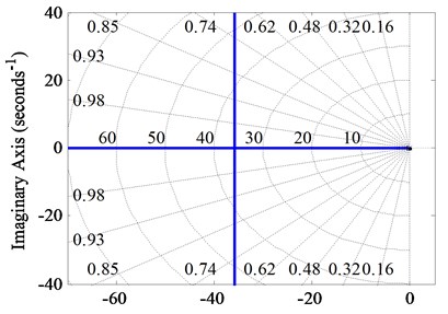
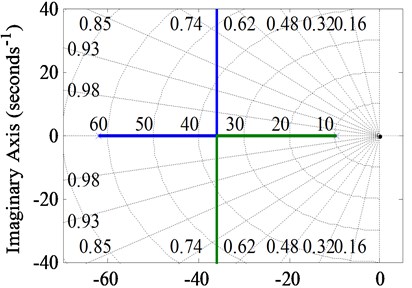
From Eq. (13), the root locus of torque regulation part is shown in Fig. 7(a), and the parameter root locus with ki2 as the gain is shown in Fig. 7(b) according to Eq. (15).
Fig. 7Root locus: a) when ki2 is not introduced, b) ki2 as the loop gain
a)
b)
According to Eqs. (13) and (15), when J and D are confirmed, the introduction of ki2 will increase the natural frequency of the second-order system, that is, the cut-off frequency of the system, such that the damping ratio is reduced. Compared Fig. 7(a) with Fig. 7(b), we can see that due to the introduction of ki2, the root locus initiation point shrinks ten-unit-length to the separation point, and eliminates the pole at the origin, so that all the closed-loop feature roots are located at the left side of the imaginary axis, which improves the stability of the control system. Meanwhile, before and after the introduction of ki2, the separation point coordinates of the root locus are both (–35.8, 0). If the selection of ki2 makes the damping ratio same, the dynamic response speed of the system will not change. Thus, the introduction of ki2 improves the stability of the system without changing the dynamic response speed of the system.
As 0 < ki2 < 138.46, the two poles of the closed-loop system are both on the real axis, is an over-damping system. With ki2 increasing, the characteristic roots evolve into conjugate complex roots so that the control system is under-damped. In comparison with [15], we can see that the system possesses a faster dynamic response speed when the ICI is inductive.
The damping ratio can be selected by ξ= 0.707 from the second-order engineering optimal value, such that ki1= 2482.
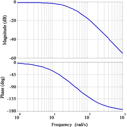
Fig. 8 shows the Bode diagram of the torque regulation loop gain of the p-f controller. The cut-off frequency of the loop is about 10 Hz, which has a good inhibitory effect on the double-line-frequency ripple of VSG output power and the detected system frequency, and the control system has enough phase margins.
In reality, the parallel operation of multiple inverters is often required. In order to enable the multiple VSGs to share the loads, it is required that the VSGs can have a consistent dynamic response, that is, the changing trend of each rotor of the VSG should keep consistent, such that it will not produce circulation or even power oscillation between the VSGs due to the difference of the rotor frequency. Hence, when the parameters of VSGs are consistent, the accurate load sharing can be achieved, so that the parallel and stable operation of the VSGs can be realized.
Fig. 8Bode diagram of the torque regulation loop gain
4. Simulations
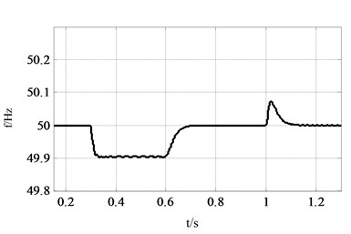
Simulations are executed in MATLAB/Simulink environment to verify the effectiveness of the proposed SFR scheme. The system parameters in simulation are listed in Table 2. For comparison conveniently, the droop control mode of the VSG is also applied, and the results are shown in Fig. 9. The initial load is 10 kW/5 kVar, and the active load increases 5 kW at 0.3 s and ends at 1.0 s, and the two integrators are put into at 0.6 s so as to make the VSG runs under the SFR mode.
Table 2Simulation parameters
Parameters | Value | Parameters | Value |
DC voltage: Vin | 800 V | fref | 50 Hz |
Line voltage | 380 Vrms | Uref | 220 V |
Sbase | 20 kVA | Power reference | 10 kW+5 kVar |
K | 0.141 | Switch frequency | 10 kHz |
KPWM | 1.6 | ICI | 0.5+j4 Ω |
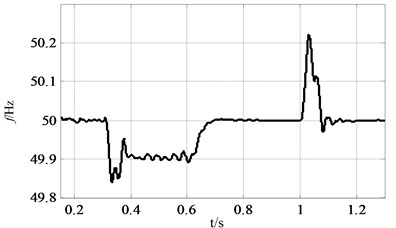
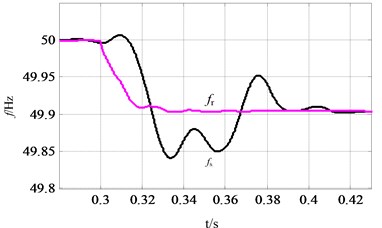
Fig. 9 illustrates the dynamic performance of active power and frequency during the loading transition at 0.3 s and 1.0 s. Before 0.6 s, VSG runs in droop control mode to realize PFR alone. From 0.3 s to 0.6 s, due to the increase of the active load, the rotor and the system frequency are around 49.9 Hz deviating from the reference value 50 Hz, which is the characteristic of the droop control. As the SFR part is put into operation at 0.6 s, the rotor and system frequency are restored to rated value after 5 fundamental frequency cycles, which fully meets the time requirement of the dynamic response of the system. Because the ICI is not inductive purely, there is a weak coupling between the active power and the reactive power of the VSG, which can be neglected.
Fig. 9Comparison between PFR and SFR: a) VSG output power waveform, b) rotor frequency curve of VSG, c) system frequency curve, d) comparison between fr and fs from 0.28 s to 0.43 s
a)
b)
c)
d)
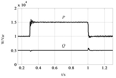
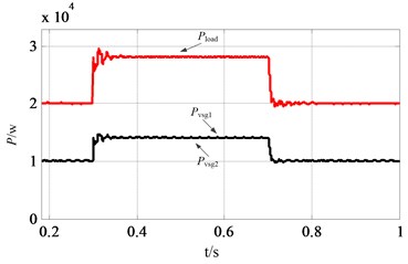
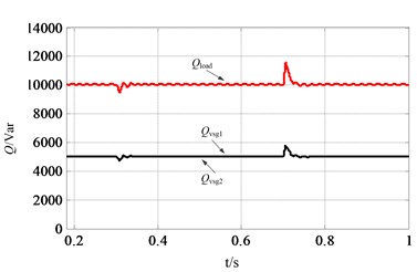
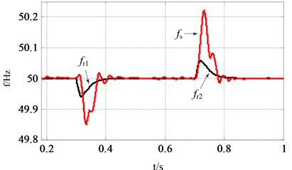
Fig. 10Waveforms of VSGs and load under the SFR mode: a) active power of the microgrid, b) reactive power of the microgrid, c) frequency of rotor1, rotor2 and system
a)
b)
c)
Furthermore, we also can observe that the rotor frequency declines before the system frequency conducts in Fig. 9(d), which demonstrates that the VSG possesses the ability to frequency support for microgrid. There is no malignant event as frequency dips, which enhances the stability of system frequency. It is stable after a short period of adjustment, which is consistent with the PFR dynamic process of the power system. And the waveform of the system frequency is more stable in the SFR mode compared to the droop control mode, which indicates that the control system possesses better stability. Due to the frequency reference of the damping part is selected as the rated value, the attenuated oscillation of rotor frequency in SG is not generated, such that the change process of rotor frequency is stable in the VSG.
To verify the stability of the parallel operation of multiple VSGs under the SFR mode, two VSGs with a capacity of 20 kVA are established, other parameters are same with Table 2. The initial load is set as 20 kW/10 kVar, and the active load increases 8 kW at 0.3 s and ends at 1.0 s. The two VSGs can share the active and reactive load accurately to realize the stable and parallel operation as shown in Fig. 10(a), (b). The coordinated dynamic performance of rotor frequency of VSG1 and VSG2 is illustrated in Fig. 10(c), and there is no power oscillation and the phenomenon of loss of synchronism between the two VSGs.
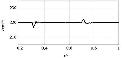
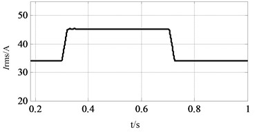
Fig. 11 shows the Vrms and Irms waveforms of PCC. There is a small fluctuation on Vrms when active power transition happens due to the weak coupling but can restore to reference quickly, as shown in Fig. 11(a). Meanwhile, it is indicated that the output current of VSGs can track the load accurately in Fig. 11(b).
Fig. 11Vrms and Irms of PCC: a) phase Vrms of PCC, b) phase Irms of PCC
a)
b)
5. Conclusions
In this paper, an improved VSG control is proposed as a novel communication-less control method in an islanded microgrid. The swing equation of the SG is applied to the p-f controller of the VSG, which makes the inverter have certain inertia. Firstly, the torque-speed characteristic of the rotor is analyzed, and then the small-signal model of the VSG is derived when the ICI is mainly inductive. Secondly, the calculation method of the integral coefficients is given, and illustrated that the introduction of the integrator can improve the stability but don't change the dynamic response of the system on the basis of small-signal model. And based on inversed voltage droop control, a control strategy about communication-less reactive power is also proposed to achieve accurate reactive power sharing. Finally, simulation results demonstrated that the proposed improved VSG control achieves the SFR whether in single or parallel operation state without power oscillation. It is verified that the improved VSG control proposed is a preferable option to the control system of DGs in microgrids.
References
-
Wang C. S., Li P. Development and challenges of distributed generation, the micro-grid and smart distribution system. Automation of Electric Power Systems, Vol. 34, Issue 2, 2010, p. 10-14+23.
-
Shu Y. B., Zhang Z. G., Guo J. B., et al. Study on key factors and solution of renewable energy accommodation. Proceedings of the CSEE, Vol. 37, Issue 1, 2017, p. 1-9.
-
Yang X. F., Su J., Lü Z. P., et al. Overview on microgrid technology. Proceedings of the CSEE, Vol. 34, Issue 1, 2014, p. 57-70.
-
Zhang W. L., Qiu M., Lai X. K. Application of energy storage technologies in power grids. Power System Technology, Vol. 32, Issue 7, 2008, p. 1-9.
-
Lü Z. P., Sheng W. X., Zhong Q. C., et al. Virtual synchronous generator and its applications in microgrid. Proceedings of the CSEE, Vol. 34, Issue 16, 2014, p. 2591-2603.
-
Beck H. P., Hesse R. Virtual synchronous machine. International Conference on Electrical Power Quality and Utilisation, 2007.
-
Zhong Q. C., Weiss G. Synchronverters: inverters that mimic synchronous generators. IEEE Transactions on Industrial Electronics, Vol. 5, Issue 4, 2011, p. 1259-1267.
-
Yuan C., Liu C., Zhang X., et al. Comparison of dynamic characteristics between virtual synchronous machines adopting different active power droop controls. Journal of Power Electronics, Vol. 17, Issue 3, 2017, p. 766-776.
-
Yang X. Z., Su J. H., Ding M., et al. Research on frequency control for microgrid in islanded operation. Power System Technology, Vol. 34, Issue 1, 2010, p. 164-168.
-
Liu S., Wang X., Liu P. X. Impact of communication delays on secondary frequency control in an islanded microgrid. IEEE Transactions on Industrial Electronics, Vol. 62, Issue 4, 2015, p. 2021-2031.
-
Guo F., Wen C., Mao J. Distributed secondary voltage and frequency restoration control of droop-controlled inverter-based microgrids. IEEE Transactions on Industrial Electronics, Vol. 62, Issue 7, 2015, p. 4355-4364.
-
Yan X. W., Wang X. H., Wang Y. R. Research on novel zero-error frequency regulation control method for microgrid. Power System Protection and Control, Vol. 45, Issue 21, 2017, p. 1-6.
-
Xu C., Liu N., Zhao H., et al. A novel frequency control strategy of microgrid based on the secondary frequency regulation of power system. Power System Protection and Control, Vol. 41, Issue 3, 2013, p. 14-20.
-
Tian Y. Q., Zheng T. W., Chen L. J., et al. The frequency control of virtual synchronous generator based on adaptive adjusting. Southern Power System Technology, Vol. 8, Issue 5, 2014, p. 76-79.
-
Li B., Zhou L., Yu X. R., et al. Secondary frequency regulation for microgrid inverters based on improving virtual synchronous generator. Power System Technology, Vol. 41, Issue 8, 2017, p. 2680-2687.
-
Liang Y., Sheng W. X., Zhong Q. C. et al. Secondary frequency regulation strategies and characteristic analysis of synchronverter-based microgrids. Proceedings of the CSEE, Vol. 37, Issue 2, 2017, p. 391-402.
-
Guo Z., Yue Q. M., Guo L., et al. Control method of dc bus voltage ripple mitigation in hybrid AC/DC microgrids. Power System Technology, Vol. 41, Issue 9, 2017, p. 2896-2904.
-
Xu H. D., Su J. H., Yang X. Z., et al. Analysis of influences of equating ways and filter circuits for virtual synchronous generator-based inverter. Control Theory and Applications, Vol. 34, Issue 8, 2017, p. 1053-1061.
-
Wu H., Ruan X. B., Yang D. S., et al. Small-signal modeling and parameters design for virtual synchronous generators. IEEE Transactions on Industrial Electronics, Vol. 63, Issue 7, 2016, p. 4292-4303.
-
Cheng C., Yang H., Zeng Z., et al. Rotor inertia adaptive control method of VSG. Automation of Electric Power Systems, Vol. 39, Issue 19, 2015, p. 82-89.
-
GB/T 12325-2008, Power quality – Frequency deviation for power system.
-
GB/T 15945-2008, Power quality – Deviation of supply voltage.
Cited by
About this article
This work is supported by Science and Technology Program of Gansu Province (Grant No. 17JR5RA083).
