Abstract
The main objective of the research was to establish movement of corn ears within the threshing crescent between the cylinder and the concave using high-speed recording method. Tangential threshing unit was used in the experimental trials. Cylinder rotation and linear velocity of rasp bars (11.00 m s-1, 14.14 m s-1 and 17.28 m s-1) were determined by using threshing cylinder covered with filler plates having 4 different shapes. During the trials, speed of corn ears within threshing crescent, number of impacts received by the corn ear, rising height of the corn ear after impact of rasp bar and time between two impacts of rasp bar to the corn ear, depending on the shape of filler plates of threshing cylinder were found. Video analysis of corn ear movement showed that the speed of corn ears movement in the threshing crescent highly depends on linear velocity of rasp bars. The average speed of corn ear within threshing crescent and number of impacts received by the corn ear were increased with increase of linear velocity of rasp bars irrespective of cylinder filler plates are used. Moreover, both above-mentioned parameters were larger in the second part of concave length than in the first one. A tendency of increase of the corn ear moving over the surface of the concave and decrease of number of impacts received by the corn ear was observable by reduction in the threshing crescent. Following reduction of linear velocity of rasp bars to 14.14 m s-1, it would be reasonable to cover the threshing cylinder with filler plates that can reduce the cross-section area between rasp bars and concave (to 94.26 cm2 in view of one gap between adjacent rasp bar). In this case, filler plates showed a substantial effect on behaviour of corn ears: they restrict a rising height of the corn ear, may be subject to additional rotational motion, deflect the corn ear to the clearance between the rasp bar and the concave bar as well as deflect threshed kernels towards concave grates.
1. Introduction
Movement of the crop flow in the threshing crescent depends on grain characteristics, length and orientation of stems, layer thickness, design and technological parameters of the threshing apparatus [1-3]. Different techniques were used for finding the speed of crop flow movement within the threshing crescent between the cylinder and the concave. Some researchers chose to attach rotating rollers [4], rotors [5] or deformation sensors [6] on the top of the concave, while others decided to insert some sensors into the crop flow and to attach the rest of them to the concave [7, 8]. The speed of crop flow movement was also measured with the inductive speed sensor, the coil of which was bound by Capron thread to the small bundle of crops fed into the threshing apparatus with the entire crop flow [9]. Some researchers, after capturing crop movement using high-speed cameras [10-13], analyzed the recorded images using computer software in order to find the speed of crop flow movement. However, the last mentioned method for wheat and other cereals flow movement is rarely used, as there are difficult to identify particular elements from the entire threshed mass.
V. Goriachkin reported that without taking into consideration resilience of the crop flow moving over the surface of the concave, the speed of crop movement can be considered to be equal to the linear peripheral threshing cylinder velocity. However, when threshing crops, rasp bars of the threshing cylinder move over the surface of the passing concave with respect to the flow of crops, whereas the latter moves – with respect to the stationary concave, i.e. the so-called sliding occurs [14]. Moving closer to the end of the concave, with the decreasing threshing crescent, the speed of crop flow movement gradually increases, however it does not achieve the numerical value of the linear peripheral velocity of threshing cylinder [2].
N. Klenin [15] found that at the beginning of the concave, the average speed of crop flow movement amounts for 3-8 m∙s-1 whereas at the end of the concave it significantly increases and amounts for approximately 20 m∙s-1. When the crop flow is fed into threshing apparatus in an orientated position, i.e. when ears enter threshing unit first, the crop flow moves faster within the threshing crescent. To find the speed of crop flow movement the following equation was made [15]:
where q – the crop flow fed into the threshing apparatus, kg·s-1; q=5.0 kg∙s-1; φ – concave wrap, rad; φ=2.58 rad; a, b, c, e – empirical coefficients, a=2.2 m∙s-1, b= 0.21 m∙s-1(kg/s)-1, c= 3 m∙s-1(rad)-1, e= 0.58 m∙s-1(kg/s)-1(rad)-1, when the diameter of the threshing cylinder Db= 0.6 m, cylinder speed nb= 955 min-1, linear peripheral velocity of threshing cylinder vb= 30 m∙s-1.
Similar dependencies were also obtained by E. Lipkovich [5] who reported that the speed of crop flow at the end of the concave was by 2-3 times that at the beginning. Moreover, the author suggested that increased speed of crop feed into the threshing apparatus result in more rapid movement of crop flow over the surface of the concave.
I. Dolgov suggested to use the following equation for finding the speed of crop movement at the beginning of the concave [16]:
where q – the crop flow fed into the threshing apparatus, kg∙s-1; Δ – thickness of the crop flow before entering the threshing apparatus, m; η – coefficient for taking into consideration exploitation of length of the threshing cylinder; lb – the length of threshing cylinder, m; γ – crop flow density, kg∙m-3.
After entering the threshing apparatus, i.e. the clearance δ between the rasp bar and the concave bar, the crop flow is compressed (Fig. 1). This is taken into consideration by introducing the crop compression degree ξ:
The crop flow is considered to be moving nonstop over the surface of the concave if ξ value does not exceed critical value ξkrit. (for wheat straw ξkrit.= 6-7) [16].
Moreover, consistent crop flow requires for the following:
where F – the force of the rasp bar at the moment of impact to the portion of crop flow, N; Δt – duration of acting force F, s; m – mass of the portion of crop flow fed into the threshing apparatus, kg.
The force of the rasp bar at the moment of impact to the crop flow is as follows:
where N – normal force of the portion of crop flow to the concave bar, N; f1 – the coefficient of friction of sliding used to take into consideration friction between the crop flow and the rasp bar; f2 – the coefficient of friction of sliding used to take into consideration friction between the crop flow and the concave bar.
Duration of acting force F is as follows:
where b – width of the operating surface of the rasp bar, m; vb – linear velocity of rasp bar, m∙s-1.
Mass of the portion of crop flow fed into the threshing apparatus is calculated as follows:
where t – time interval between the consecutive rasp bar impacts, s; Db – diameter of the threshing cylinder, m; M – number of rasp bars, units.
Normal force of the portion of crop flow to the concave bar is calculated as follows:
where p – pressure of the portion of crop flow on the concave bar, Pa; b0 – width of the concave bar, m.
Fig. 1Threshing apparatus: 1 – rasp bar; 2 – concave; 3 – concave bar; 4 – rods; δ – threshing crescent between the rasp bar and concave bar; b – width of a rasp bar; b0 – width of the concave bar; ω – angular velocity of threshing cylinder
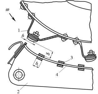
Wheat threshing research showed that the concave bar is under force of N= 2.59 kN when density of wheat flow γ= 40 kg∙m-3, moisture content – w= 22 %, grain-straw ratio – 1:1.5, width of the concave bar – b0= 0.01 m, width of the operating surface of the rasp bar – b= 0.03 m, threshing crescent between the rasp bar and the concave – δ = 0.016 m, length of threshing cylinder – lb= 1.5 m, diameter – Db= 0.8 m, number of rasp bars – M= 10, the coefficient taking into consideration exploitation of length of the threshing cylinder – η= 0.8 m, and crop compression degree ξ= 6 [16].
Theoretical calculations often assume [5] that the normal force N of the portion of crop flow to all the concave bars is the same, i.e. it does not vary in the entire length of the concave. This assumption can also be made when analyzing crop movement, as force N is mainly dependent on pressure p of the portion of crop flow on the concave bar, which is constant under constant amount of straw within the threshing apparatus (with reducing amount of grain only, as their separation through concave takes place).
Laboratory research showed that force N at the end of the concave was by 2-2.5 times that in the front (when threshing crescent was: 16 mm at the inlet, and – 4 mm at the outlet) [5]. With increasing crop flow, the force N acting on the concave bars increases, whereas with increasing velocity of rasp bar it decreases [5].
When threshing corn ears, numerical value of the pressure p is assumed to decrease when moving closer towards the end of the concave, although threshing crescent between the cylinder and the concave decreases, too. This phenomenon can be explained as follows: only one quarter of the total mass of the flow of corn ears fed into the threshing apparatus is comprised of impurities (husk leaves, cobs, tassels and stalks) [17]. Whereas when threshing crops, straw accounts for 40 % of the total mass of the flow fed into the threshing apparatus, for deformation of which force N is mainly consumed. Consequently, movement of the corn ear flow being threshed is different from the movement of the cereal crop flow. To analyze the movement of particular elements of the corn ear flow within the threshing crescent, a high-speed recording method could be applied.
The aims of this study were to establish movement of corn ears within the threshing crescent and to determine the threshability of corn ears considering to the shape of the threshing cylinder filler plates.
2. Materials and methods
Experimental trials were conducted in 2016 at the laboratory using the stationary tangential single-cylinder threshing unit (Fig. 2). Cylinder rotation (350 min-1, 450 min-1 and 550 min-1) and linear velocity of rasp bars (11.00 m s-1, 14.14 m s-1 and 17.28 m s-1) were determined using a variable frequency drive.
Fig. 2The scheme of the stationary unit used for threshing corn ears [12]: 1 – tray; 2 – corn ears; 3 – feed lever; 4 – threshing cylinder; 5 – the grate-bar type concave; 6 – threshing cylinder filler plates; 7, 8, 9 – tanks for collecting kernels separated through individual sections of the concave; 10 – threshed kernel collection tank; 11 – the device for measuring electric current, voltage and wattage; 12 – electric motor; 13 – belt variator; 14 – signal inverter; 15 – optical sensor of cylinder rotation frequency; 16 – optical sensor of electric motor rotation frequency; 17 – sensor of pressure force at the end of the concave; 18 – electronic weighing scale; 19 – tensoresistor load sensors; 20 – computer; 21 – high-speed video recording camera; 22 – frequency transducer; 23 – locking torque sensor; 24 – signal amplification and power supply unit for weighing scale; 25 – back beater; 26 – frame of the stationary threshing unit
![The scheme of the stationary unit used for threshing corn ears [12]: 1 – tray; 2 – corn ears; 3 – feed lever; 4 – threshing cylinder; 5 – the grate-bar type concave; 6 – threshing cylinder filler plates; 7, 8, 9 – tanks for collecting kernels separated through individual sections of the concave; 10 – threshed kernel collection tank; 11 – the device for measuring electric current, voltage and wattage; 12 – electric motor; 13 – belt variator; 14 – signal inverter; 15 – optical sensor of cylinder rotation frequency; 16 – optical sensor of electric motor rotation frequency; 17 – sensor of pressure force at the end of the concave; 18 – electronic weighing scale; 19 – tensoresistor load sensors; 20 – computer; 21 – high-speed video recording camera; 22 – frequency transducer; 23 – locking torque sensor; 24 – signal amplification and power supply unit for weighing scale; 25 – back beater; 26 – frame of the stationary threshing unit](https://static-01.extrica.com/articles/19457/19457-img2.jpg)
Investigation was carried out using a threshing apparatus equipped with a concave with surface area of 0.96 m2, for which the active separation area was equal to 69.19 %. Before starting the trials, the clearance between the cylinder rasp bars and the concave crossbars was set to 36 mm in the front, 29 mm in the middle and 22 mm at the end of concave. The clearance between the cylinder rasp bars and the concave crossbars was also set by the following determined biometric indicators of the corn ears, variety Pioneer P8000: max. ear diameter 44.27±0.69 mm, ear length 174.97±4.91 mm, max. cob diameter 26.29±0.85 mm, total ear weight 212.29±13.48 g, kernel weight (33.85 % moisture content) 150.66±9.40 g. Moisture content of kernel was 33.85±0.97 %, that of husk leaves – 34.74±2.05 %, of cobs – 53.25±0.55 %, of tassels – 42.34±2.66 % and of stalks – 80.31±0.62 %.
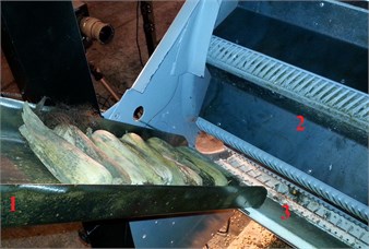
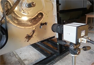
Corn ears were placed one by one (10 corn ears at once) on a special tray bottom (Fig. 3) and then rolled parallel to the threshing cylinder shaft into the clearance between the cylinder rasp bars and the first concave crossbar i.e. threshing crescent. When the fixed threshing cylinder rotation frequency was achieved, the feed lever of tray was opened, and corn ears were rolled down into the threshing crescent. Corn ear movement was followed using a high-speed camera Photron Fastcam 1024 PCI (Photron, Japan) at 2000 frame per second, a high-intensity discharge light and the software Tema (Image Systems Motion Analysis, Sweden).
Fig. 3Corn ear threshing unit and high-speed video camera: 1 – tray with corn ears feed lever; 2 – filler plate; 3 – concave
a)
b)
After every threshing trial, non-threshed kernels were detached from each corn cob by hand and weighed separately on a scale Kern CM 320-1N (Kern, Germany). The average percentage of non-threshed kernel was calculated.
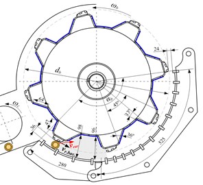
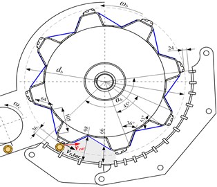
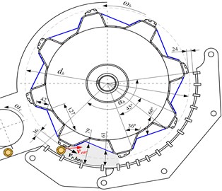
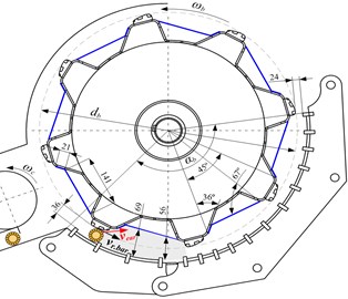
During the experimental trials, speed of corn ears within the threshing crescent (cylinder-to-concave clearance), number of impacts received by the corn ear, rising height of the corn ear after impact of rasp bar and time between two impacts of rasp bar to the corn ear, depending on the shape of filler plates (FP) of threshing cylinder were found. Analysis was performed at the first part (0.280 m) and the second part (0.525 m) of the concave length. For the trials, steel filler plates of 4 different shapes were used (Fig. 4). Covering threshing cylinder with FP-I, the cross-section area of one gap between adjacent rasp bars and concave was 119.91 cm2 (Fig. 4(a)), FP-II – 105.27 cm2 (Fig. 4(b)), FP-III – 94.26 cm2 (Fig. 4(c)), FP-IV – 83.80 cm2 (Fig. 4(d)).
Each trial was repeated thirty times, i.e. thirty ears were analyzed. Measurement data were assessed with the statistical software Statistica 10.0 using methods of dispersion and correlation-regression analysis. Arithmetic averages, their standard deviations and confidence intervals at 0.95 probability level were found [18].
3. Results and discussion
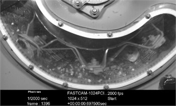
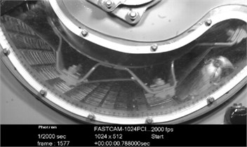
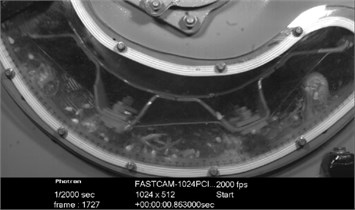
High speed video analysis showed that the speed of corn ears movement in the threshing crescent highly depends on linear velocity of rasp bars. Behaviour of single corn ear beside the second concave crossbar, i.e. after the first impact, demonstrated that corn ear under its axial turning raised into space of gap between adjacent rasp bars. Rising speed of the corn ear amounted to 3.0 m·s-1, 3.5 m·s-1 and 3.8 m·s-1 at a linear velocity of rasp bars of 11.00 m·s-1, 14.14 m·s-1 and 17.28 m·s-1, respectively. At the highest linear velocity (17.28 m·s-1), a rising not more than up to 42 mm was found because of impact of the next rasp bar to the corn ear. When rasp bars moved at the above discussed linear velocity of rasp bars and speed of the corn ear movement over the surface of the concave was approximately 1 m·s-1, a maximum number of impacts was provided to the corn ear when compared with rasp bars linear velocity of 11.00 m·s-1. Previous studies have demonstrated that corn ears are fully threshed when rasp bars move at linear velocity of 17.28 m·s-1 [12]. However, the recommended linear velocity of rasp bars for corn ear threshing is 10-15 m∙s-1 [15] as increase of linear velocity causes kernel damage [19]. The effect of FP-I and FP-II to behaviour of corn ear by rasp bars movement at linear velocity of 17.28 m·s-1 was not substantial. Using FP-III and FP-IV with smaller gap between adjacent rasp bars resulted in increasing tendency of corn ears movement over the surface of the concave and decreasing of number of rasp bars impacts. The corn ear after impact of rasp bar is rotated around its axis by angle of 40-50°, regardless of the shape of cylinder gaps between adjacent rasp bars. Furthermore, most corn cobs are broken into three or four pieces.
Fig. 4Filler plates of threshing cylinder: a) – FP-I; b) – FP-II; c) – FP-III; d) – FP-IV: ωb – angular velocity of the cylinder; ωc – angular velocity of the feeder conveyor; db – diameter of the cylinder; αb – concave wrapping angle; vr.bar – linear velocity of rasp bars; vear– speed of corn ear
a)
b)
c)
d)
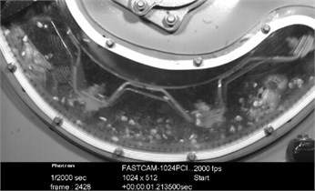
When the linear velocity of rasp bars was decreased to 14.14 m·s-1, the corn ear was rotated around its axis into gap between adjacent rasp bars till the next impact of rasp bar with increased angle (80-90°) and raised higher. In this case, the effect of the shape of FP (particularly FP-III and FP-IV) is more substantial as rising height of the corn ear is restricted (Fig. 5). When FP-I was used at the above-mentioned linear velocity of rasp bars, an impact was received not from the rasp bar but from working plane of cylinder gap between adjacent rasp bars.
Table 1Speed of the corn ear movement in the threshing crescent and number of impacts received by the corn ear
Linear velocity of rasp bar, m·s-1 | Number of rasp bar impacts received by the corn ear, units | Speed of the corn ear in the threshing crescent, m·s-1 | Rising height of the corn ear after impact of rasp bar, mm | Time period between two impacts to the ear, s | ||||
I part | II part | Total at concave length | I part | II part | Average at concave length | |||
FP-I | ||||||||
11.00 | 3.63±0.23 | 4.43±0.48 | 8.06±0.65 | 2.80±0.15 | 3.72±0.35 | 3.26±0.22 | 96 | 0.029 |
14.14 | 4.10±0.33 | 4.47±0.35 | 8.57±0.50 | 3.19±0.23 | 4.83±0.31 | 4.01±0.28 | 75 | 0.022 |
17.28 | 4.70±0.77 | 4.83±0.35 | 9.53±0.82 | 3.50±0.20 | 5.02±0.45 | 4.26±0.31 | 42 | 0.015 |
FP-II | ||||||||
11.00 | 3.23±0.23 | 4.50±0.36 | 7.73±0.50 | 2.92±0.18 | 3.83±0.24 | 3.38±0.20 | 72 | 0.028 |
14.14 | 3.90±0.36 | 4.43±0.32 | 8.33±0.53 | 3.23±0.21 | 4.83±0.34 | 4.03±0.28 | 50 | 0.021 |
17.28 | 4.34±0.27 | 5.00±0.35 | 9.34±0.48 | 3.43±0.27 | 5.51±0.40 | 4.47±0.36 | 37 | 0.015 |
FP-III | ||||||||
11.00 | 3.41±0.22 | 3.42±0.28 | 6.83±0.25 | 2.95±0.19 | 5.00±0.24 | 3.98±0.31 | 70 | 0.029 |
14.14 | 3.67±0.18 | 4.17±0.37 | 7.83±0.45 | 3.46±0.18 | 5.26±0.33 | 4.36±0.53 | 50 | 0.022 |
17.28 | 3.90±0.23 | 4.40±0.50 | 8.30±0.48 | 3.68±0.22 | 5.81±0.54 | 4.74±0.56 | 35 | 0.015 |
FP-IV | ||||||||
11.00 | 3.33±0.25 | 3.10±0.25 | 6.43±0.29 | 2.78±0.16 | 5.53±0.45 | 4.16±0.42 | 65 | 0.031 |
14.14 | 3.79±0.21 | 3.41±0.22 | 6.90±0.36 | 3.36±0.21 | 6.62±0.48 | 4.99±0.30 | 45 | 0.024 |
17.28 | 3.90±0.20 | 3.80±0.44 | 7.70±0.49 | 3.27±0.21 | 7.05±0.62 | 5.16±0.40 | 30 | 0.016 |
As a result of using other cylinder gaps between adjacent rasp bars, an impact to the corn ear was provided from the rasp bar. Additionally, using of FP-III and FP-IV caused a rising of the corn ear to FP, movement towards the concave and rotating over the surface of the FP (Fig. 5(d)). In summary of corn ears threshing data when linear velocity of rasp bars amounted to 14.14 m·s-1, an advisable use of FP-III and FP-IV was observed when compared to the previously presented study [12].
Fig. 5Movement of the corn ear depending on FP: a) FP-I, b) FP-II, c) FP-III, d) FP-IV
a)
b)
c)
d)
High speed video analysis showed that the shape of FP-III and FP-IV has a substantial impact on a faster kernel separation through the concave too, i.e. deflects threshed kernels towards concave grates. A smaller gap between adjacent rasp bars and suitable shape of FP cause kernel floating towards the concave, resulting in less damage of kernel [17].
To summarize the threshing trials, the average speed of corn ear within threshing apparatus and number of impacts received by the corn ear were increased with increase of linear velocity of rasp bars irrespective of FP are used. Moreover, both above-mentioned parameters were larger in the second part of concave length than in the first one.
Corn ear threshing trials showed that the least amount of non-threshed kernels was observed at a linear velocity of 14.14 m·s-1 when the threshing cylinder was covered with FP-III an FP-IV. Analysis of kernel loss revealed no significant difference when compared with above mentioned filler plates. The proportion of non-threshed kernels amounted then to 0.40±0.11 % and 0.26±0.17 %, respectively. The maximum kernel loss (1.49±0.17 %) was observed when the threshing cylinder was covered with FP-I. Using the threshing cylinder covered with FP-II resulted in kernel loss to 0.76±0.23 %.
4. Conclusions
Analysis of corn ear behaviour in the threshing apparatus recorded by high-speed video camera and the video material analysis demonstrated that the speed of corn ears movement in the threshing crescent highly depends on linear velocity of rasp bars. The average speed of corn ear within threshing apparatus and number of impacts received by the corn ear were increased with increase of linear velocity of rasp bars irrespective of FP are used. Moreover, both above-mentioned parameters were larger in the second part of concave length than in the first one.
It was found that the corn ear under its axial turning is raised into space between adjacent rasp bars after the first impact. Rising speed of the corn ear amounted to 3.0 m·s-1, 3.5 m·s-1 and 3.8 m·s-1 at a linear velocity of rasp bars of 11.00 m·s-1, 14.14 m·s-1 and 17.28 m·s-1, respectively. Rising height of the corn ear and time period between two impacts of rasp bars to the corn ear are decreased twice with increase of linear velocity of rasp bars irrespective of FP are used. At linear velocity of 17.28 m·s-1, an impact of FP on a behaviour of the corn ear was not significant. However, it was found that most corn cobs were broken into three or four pieces.
A tendency of increase of the corn ear moving over the surface of the concave and decrease of number of impacts received by the corn ear was observable by reduction of space between adjacent rasp bars. Following reduction of linear velocity of rasp bars to 14.14 m∙s-1, it would be reasonable to cover the threshing cylinder with FP-III and FP-IV that reduced the space between adjacent rasp bars. In this case, filler plates showed a substantial effect on threshing efficiency and behaviour of corn ears: they restrict a rising height of the corn ear, may be subject to additional rotational motion, deflect the corn ear to the clearance between the rasp bar and the concave bar as well as deflect threshed kernels towards concave grates.
References
-
Klenin N. I., Kiselev S. N., Levshin A. G. Agricultural Machinery. Kolos, Моscow, 2008, (in Russian).
-
Bajmetov R. I., Astanakulov K. D., Riazanov A. V. The nature of crop movement inside the threshing apparatus. Mechanisation and Electrification in Agriculture, Vol. 38, 2004, p. 86-89, (in Russian).
-
Kim S. H. Combine Simulation Model to Evaluate Design and Operation Alternatives. Texas Tech University, Texas, 1990.
-
Vockij Z. I. About crop movement within the threshing crescent. Research Papers cHimesH, Vol. 35, 1968, p. 79-87, (in Russian).
-
Lipkovich E. I. Processes of Threshing and Separation in Threshing Apparatus of Combine Harvesters. Vniptimesh, Zernograd, 1973, (in Russian).
-
Liashenko A. A., Kosilov O. N. Methods and results of the study of some parameters of cereal threshing during threshed material movement in the threshing crescent of a combine harvester. Vestnik DGTU, Vol. 8, Issue 3, 2008, p. 287-292, (in Russian).
-
Miu P. I., Kutzbach H. D. Mathematical model of material kinematics in an axial threshing unit. Computers and Electronics in Agriculture, Vol. 58, 2007, p. 93-99.
-
Wacker P. Comparison of axial and tangential threshing units in cereal harvesting. Landtechnik, Vol. 6, 1988, p. 264-266, (in German).
-
Zajcev A. A., Zajceva N. V. Investigation of the Speed of Threshed Material Movement Within the Threshing Crescent. Rostov na Donu, 1988, p. 24-29, (in Russian).
-
Gasparetto E., Febo P., Pessina D., Rizzato E. High speed movie observations on an axial flow combine harvester cylinder. Proceedings of the 11th International Congress on Agricultural Engineering Land and Water Use, Netherlands, Vol. 3, 1989, p. 1935-1942.
-
Petkevichius S., Shpokas L., Kutzbach H. D. Investigation of the maize ear threshing process. Biosystems Engineering, Vol. 99, 2008, p. 532-539.
-
Kiniulis V., Steponavičius D., Jasinskas A., Andriušis A., Jovarauskas D., Juknevičius D. Combine harvester threshing cylinder constructive parameters. Proceedings of the 44th International Symposium on Agricultural Engineering, Croatia, 2016, 143-153.
-
Li X. P., Ma F., Gao L. X. High-speed photograph analysis on threshing process of corn seed. Transactions of the Chinese Society for Agricultural Machinery, Vol. 40, Issue 11, 2009, p. 46-49.
-
Derevenko V. V., Severin Y. D. Machines for Cereal Harvesting: Theory and Calculation. Publishing Kuban Agrarian University, Krasnodar, 1991, (in Russian).
-
Klenin N. I., Sakun V. A. Agricultural and Melioration Machinery. Kolos, Моscow, 1994, (in Russian).
-
Dolgov I. A. Agricultural Harvesting Machinery: Design, Theory, Calculation. DGTU, Rostov na Donu, 2003, (in Russian).
-
Kiniulis V., Steponavičius D., Andriušis A., Kemzūraitė A., Jovarauskas D. Corn ear threshing performance of filler-plate-covered threshing cylinders. Mechanika, Vol. 23, Issue 5, 2017, p. 714-722.
-
Olsson U., Engstrand U., Rupšys P. Statistical Methods SAS and MINITAB. LŽŪU Press Centre, Akademija, 2000, (in Lithuanian).
-
Špokas L., Steponavičius D., Butkus V., Kiniulis V. Substantiation of the rational technological parameters for threshing high-moisture corn ears. Proceedings of 4th International Conference on Rural Development, Vol. 6, Issue 3, 2013, p. 139-146.
