Abstract
The purpose of this paper is to evaluate the responses of horizontally curved bridges that are affected by vehicles load. The effect of vehicles dynamic loads on bridges is influenced by factors such as geometric characteristics of structures and moving loads specifications. To consider the effect of dynamic loads in design of bridges, static load increases with a coefficient which is called “impact factor” in Design Codes. In this paper, by examining the effect of curvature of deck and the speed of vehicles which are passing along the bridge on the dynamic response of bridge, set of new equations for DAF is presented. For this purpose, dynamic analysis is performed for seven bridges with different radius of curvature under the influence of AASHTO truck. In the case study models, it can be seen that the separation of impact factor into two different coefficients; support reaction and displacement responses make bridge design more economical and safer. Reduction of the curvature radius decreases dynamic amplification factor (both coefficients). To identify the possible damages of the examined bridges in the early stages of the advent a new index is presented. This index can predict the damages due to moving vehicles.
1. Introduction
The estimation of structure response to dynamic loads is one of the most important factors to increase the safety and providing suitable service for users of bridges. In addition to the essence of dynamic load, the irregularity and the geometry of bridges are the sufficient factors in determination of response of structures. A significant portion of bridges that are built in major cities, are those which are horizontally curved. These bridges are often used in large intersections to facilitate traffic, as well as improving the sense of aesthetics. Structural complexity of curved bridges has led researchers to study the specification of dynamic response of bridges.
By increasing the magnitude of the dynamic interaction forces of heavy vehicles passing at high speed as well as increase the volume of road traffic, the response of bridge under moving load has concerned designer of bridges. According to AASHTO code [1], static load that is equivalent of moving vehicle increases with Impact Factor (IF). However, the defined equation for dynamic amplification factor (DAF) is a function of span length, researches show that DAF depends on various factors like bridge geometry, essence of moving load and interaction of bridge and vehicle. Incorrect estimation of impact of moving vehicle can cause damages in the future.
Fafard et al. [2] carried out the dynamic analysis for a straight continuous bridge. The DAF was obtained for displacement, strain and support reaction. Numerical results indicated that DAF calculated from the displacement is less than DAF obtained from strain as well as reaction force.
Zhang et al. [3] proposed a method to calculate the IF for composite concrete–steel cellular straight bridges. The impact factors obtained for bending moment and displacement were calculated much less than this amount for support reaction. Daneshjoo and Hamidi [4] conducted an investigation about train impact on railway steel bridges with different span length. They observed that the IF dramatically grows at high speed of the train. Huang [5] studied the influence of traffic dynamic load on arch bridges. They reported that the AASHTO equation that is obtained according to a number of simple span bridges is not beneficial for other bridges like arch bridges. In their study the obtained results show that the IF of arch bridges is broken up into two different coefficients for axial force of vertical elements as well as bending in span mid of bridge.
Senthilvasan [6] stated that the position of the vehicle in the transverse and longitudinal directions affects the DAF. In their analysis, it was found that torsion modes due to curvature of the deck considerably influence the DAF. Rezaiguia [7] found that when the load is applied far from the central axis of the deck, the impact factor (IF) obtains in the considerable presence of torsion modes.
In the studies that are reported above it is observed that the various factors play significant role in determination of impact factor. So, it is the reason of incompatibility in the consequences of different researches. There have been many researches that are reported in the literature on the dynamic behavior of straight bridge as well as vehicle- bridge interaction. However, according to the knowledge of the authors the dynamic response of concrete horizontally curved bridge is not clear enough. In curved bridges, the characteristic of dynamic response depends on the amount of deck curvature as well as speed and causes the DAF to change. In order to provide a clear understanding of the curved bridge – vehicle interaction more researches are required. Novel equations for DAF causes safe and economical design. The potential of damages in bridges can have been studied by examining of impact factor. The identification of structural damages in the early stages can prevent from abrupt fracture and high costs of repairing. In recent years scientists take account of vibration methods to identify damages because of their features like non-destructive nature and capability to identify the place of damages that are unavailable and out of sight.
Vibration based methods in identifying structural damages like using modal strain energy have been successful [8-10]. However, in curved bridges by increasing the number of sensors, the effect of higher modes must have been considered. While increase in the number of sensors can increase costs and decreases the accuracy of sampling due to existing noise [11].
The purpose of this research is to examine the effect of distance between truck axels, the curvature of the deck and the speed of vehicle on the impact factor and to propose a new method for identifying of damages based on dynamic response of Horizontally Curved Bridges under the influence of moving load. To calculate DAF, in addition to displacement response, the dynamic response that is related to support reaction is also taken into account.
2. Finite element model
In this study, a set of concrete horizontally curved bridges which are presented in Ref. [12] are modeled by using Finite Element Method (FEM). Some more detailed modelling techniques of bridge elements can be found in [13-16]. Bridges with the subtended angle between 0-90 are modeled in this research. The deck of each bridge includes five spans with a length of 15m and the total length of 75 m and is constructed by in situ concrete system. The bridge deck is modeled in three dimensional forms by using a four-node shell elements formulation that combines detached membrane and plate-bending behavior. Transitional in-plane stiffness component and rotational stiffness component in the direction of normal vector of element plan are considered in the membrane behavior. Intermediate piers are constituted of columns and cap beams. The cap beams material is reinforcement concrete and the length, width and thickness of them are 9.8 m, 1.5 m and 1 m respectively. Each pier is comprised of 2 columns with a diameter of 1.2 m and a height of 10 m bellow the cap beams. The columns and cap beams are modeled by frame elements. The mentioned element has 12 degrees of freedom, which includes the effects of deformations due to axial force, biaxial shear, biaxial bending and torsion. The finite element model of an instance bridge is shown in Fig. 1. Fig. 2 indicates a schematic representation of the plan and the radius of the curvature (R) which is related to the subtended angle presented in Table 1.
The kinds of supports that are used in the bridges presented in this study are elastomeric bearings. The place where the deck of bridge is located on each abutment, three neoprene numbers exist. On the bridges, only 2 expansion joints are used in the abutments locations and there is no expansion joint on the Intermediate piers. Lateral stiffness of the neoprene is considered as a part of effective stiffness of the abutments. These effects are considered as linear equivalent springs in modeling. The influence of longitudinal vibration of the deck can be ignored because of considering the expansion joints along the bridge in the abutments locations. Therefore, abutments stiffness is not taken into account and the amount of stiffness in this direction is equal to neoprene stiffness magnitude which is calculated 222 ton/m. Due to the use of concrete blocks along transverse direction, the stiffness of abutments is considered to be rigid. With combination of foundation transverse stiffness and abutments in series, the equivalent stiffness is equal to foundation- abutment transverse stiffness. The equivalent stiffness along perpendicular direction is obtained in the same manner and is equal to foundation- abutment vertical stiffness.
Fig. 13-Dimensional view of the finite element model of the curved bridge
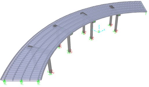
Fig. 2Bridge geometry in horizontal plan t model
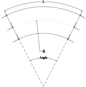
Table 1Geometric characteristic of under study bridges
Angle (°) | 0 | 15 | 30 | 45 | 60 | 75 | 90 |
R (m) | ∞ | 286 | 143 | 95 | 71 | 57 | 47 |
In order to identify the specification of the connection between columns and cap beam, as well as cap beam and deck, the connective elements are used. Since the columns rebar are completely engaged with cap beam and the deck, the rebar, cap beam concrete and deck became integrated. Therefore, connections between these parts in all degrees of freedom are considered to be rigid. The equivalent stiffness magnitudes of foundation applied for Intermediate piers and abutments are calculated according to FEMA 357 and are tabulated in Table 2; which Kx, Ky and Kz are transitive stiffness along X, Y and Z directions respectively and Kxx, Kyy, Kzz are rotational stiffness around X, Y and Z axes respectively.
Table 2The equivalent stiffness of Intermediate piers and abutment
K | Piers foundation stiffness (T/M)&(T.M) | Abutment foundation abutment (T/M)&(T.M) |
Kx | 131817 | 222 |
Ky | 138066 | 141953 |
Kz | 133842 | 146160 |
Kxx | 2819508 | 0 |
Kyy | 6709205 | 0 |
Kzz | 5209602 | 0 |
In this study, the materials used are elastic and homogeneous. Also, assuming small deformations, the structure is analyzed in the elastic region. It is assumed that the deck surface is suitable and smooth. The geometric characteristics of the Intermediate pier of the bridges and the deck are shown in Fig. 3 and Fig. 4 respectively.
Fig. 3Geometry of the bridge’s pier
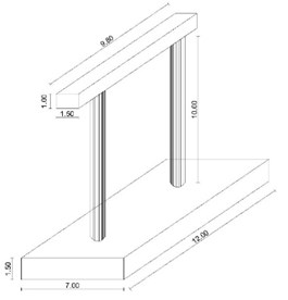
Fig. 4Cross section of the deck

The curvature influence of the bridge is stated as the ratio of the arc length to the curvature radius of the deck (L/R), where R is the distance from the arc center to the center line of the deck. The values of curvature radius are selected based on Ontario Highway Geometric Design Standards, which according to this standard; the value of R should be at least 45 meters. The modelling procedure is verified by comparing the results with Jelodarian models [12] as presented in Table 3.
Table 3Comparisons of the results of present study and reference [12]
Bridge angle (°) | Comparative responses | Jelodarian (2006) | Present study | Differences | Verified results |
0 | First period | 0.82 | 0.788 s | 0.03 | Verified |
Second period | 0.449 | 0.438 s | 0.01 | Verified | |
15 | First period | 0.817 | 0.786 s | 0.03 | Verified |
Second period | 0.452 | 0.441 s | 0.01 | Verified | |
30 | First period | 0.813 | 0.786 s | 0.03 | Verified |
Second period | 0.461 | 0.450 s | 0.01 | Verified | |
45 | First period | 0.806 | 0.787 s | 0.02 | Verified |
Second period | 0.477 | 0.466 s | 0.01 | Verified | |
60 | First period | 0.797 | 0.784 s | 0.01 | Verified |
Second period | 0.499 | 0.489 s | 0.01 | Verified | |
75 | First period | 0.785 | 0.789 s | 0.00 | Verified |
Second period | 0.528 | 0.518 s | 0.01 | Verified | |
90 | First period | 0.771 | 0.788s | 0.02 | Verified |
Second period | 0.564 | 0.557 s | 0.01 | Verified |
3. Vehicle model
Moving force model is one of the methods uses to model a vehicle for dynamic analysis of bridge influenced by vehicle passing. In this method, the load of each wheel is assumed to be a concentrated load and the inertia due to the mass is ignored. In many cases, especially when the ratio of vehicle mass to bridge mass is small, the inertia caused by vehicle can be ignored and the evaluation of bridge dynamic response is sufficiently accurate. A number of researchers such as Zhang [3] applied this method to model a vehicle for the dynamic analysis.
Increasing details of moving vehicle model does not have a great influence on the bridge response [17]. Karoumi [17] conducted a survey on bridge dynamic response by considering three different vehicle models as follows: Moving force model, moving mass and sprung mass model. The results indicated that, dynamic responses to the three vehicle models are almost identical and the vehicle model did not have a significant effect on the bridge responses for smooth surface.
Considering that the purpose of this research work is to study the dynamic responses of the curved bridge influenced by moving load under the assumption of a smooth surface, it is not essential to increase the details in truck modeling. Therefore, the moving force model is used. For dynamic loading of the considered bridges the AASHTO standard truck (Hs20-44) is used. The weight of this truck is 320 kN and its axle distance ranges from 4.25 to 9 m. In the present study, the truck is modeled by 6 concentrated forces. The allowable speed of 120 km/h is considered to be usual on highways, in most regions of the United States and Iran. The allowable speed of curved bridges is restricted by super elevation and Coefficient of side friction force between the truck tire and the road surface. Therefore, the highway design speed can be obtained as Eq. (1) [18]:
where, e is super elevation, f coefficient of side friction force between the vehicle tire and the road surface and r is the curvature radius of the bridge.
The super elevation of the curved bridges is determined by the design speed and annual weather conditions. In severe winter conditions, this amount is recommended to be 0.06. In this paper, the super elevation of 0.08 is considered to determine allowable speed in the case of horizontally curved bridges. The friction force between the vehicle tire and bridge surface is significantly dependent on pavement type. The allowable speed increases through the growth of side friction force. On the other hand, centrifugal force due to horizontally curved bridges causes the passengers to be unpleasant. In this study, the coefficient of side friction force is considered to be 0.18. The allowable truck speed is calculated based on Eq. (1) and is indicated in Table 4.
Table 4The allowable truck speed passing in curved bridges
Bridge subtended angle (°) | 0 | 15 | 30 | 45 | 60 | 75 | 90 |
Allowable speed (km/h) | 120 | 100 | 70 | 60 | 50 | 45 | 40 |
4. Dynamic analysis of the bridge affected by moving load
Dynamic response of bridges to passing vehicles has always been a fascinating subject for structural engineers. Due to the especial importance of basics principles in the study of bridge vibration affected by moving vehicle, the dynamic response of a simple curved beam under the influence of moving load is investigated. In this section, the displacement of a simple curved beam affected by a unit of moving load is calculated and its equation is derived. By solving the equation of motion of this beam, according to the principle of superposition, the equations can be generalized for several moving loads, different support conditions, etc. In Fig. 5 a simple beam is shown in which a moving load passes at a constant speed. In the calculations the gravity of the vehicle is just considered. By assuming the low ratio of vehicle weight to bridge weight, the mass moment of inertia is ignored.
Fig. 5The horizontally curved beam affected by moving load [15]
![The horizontally curved beam affected by moving load [15]](https://static-01.extrica.com/articles/19370/19370-img5.jpg)
According to Ref. [19] the motion equations for vertical vibration of the curved beam is presented as follows:
ρJ¨θx+EIzR(u''y-θxR)+GJ(θ''x+u''yR)=0,
where, m denotes the mass per unit length, and δ(x) is Dirac’s delta function.
The term on the right hand side of Eq. (2) represents the effect of the vertical moving load fv where fv=-mvg. After solving motion equation, the amount of vertical displacement of the curved beam [uy(x,t)] is obtained as Eq. (3):
×{-1ρJ[EIzR2+GJ(πL)2]}-(πvL)2{-1ρJ[EIzR2+GJ(πL)2]}+{1m(πL)2[EIz(πL)2+GJR2]}-ω2v1-(πvL)2
×[sinπvtL-(πvLωv1)sinωv1t]sinπxL.
By considering equation that is mentioned above, the first vibration mode of the curved beam is only taken into consideration. In order to solve the equation precisely, more modes are required. In practice, due to short-term influence of moving load on the bridge, the first mode is significantly excited [19]. Considering the first mode of vibration is usually acceptable for dynamic analysis of simple structural systems. In this way, the problem is altered to a single degree of freedom system. Solving this equation is much easier than solving multi degree of freedom system. Applying the equation mentioned above is not usually proper for more complex structural systems. Dynamic analysis of the bridges under moving load can be also carried out by finite element methods. Finite element methods have great potential to analyze various structures. Using this capability, three-dimensional bridges can be modeled including many details.
5. Dynamic amplification factor calculate
The ratio of the maximum dynamic response of the structure to the maximum static response of the same structure under the influence of the same load at the same cross section of the bridge deck is called the Dynamic Amplification Factor (DAF). In order to engage the dynamic effects due to moving vehicle in design, the amount of DAF or impact factor is obtained as Eq. (4) [20]:
where Rdyn and Rst denote the dynamic response and static response respectively.
In Daneshjoo and Hamidi [4] study the dynamic response of displacement of mid span is utilized to calculate the impact factor. In the present study, to calculate DAF, the dynamic response of support reaction is taken in to account as well as dynamic response of displacement. In order to determine the DAF of 7 bridges model, dynamic and static analysis is performed with different truck speed under the same loading condition. The width of the studied bridges is 11 m and each of them includes three traffic lanes. The loading truck is placed at the farthest traffic lane of the bridge with respect to arc center. The loading is carried out separately, regardless of concurrency effects and reverse traffic. This traffic lane has been selected because the most dynamic effect of moving load is observed in this traffic lane that is related to other traffic lanes. In dynamic analysis, direct integration method is used whereas a constant time step of 0.01 is defined. The analysis duration is equal to the span of the moving load passing through the bridge. In each of loading, time history of mid span displacement and support reaction is obtained by passing moving loads at different speeds. After dynamic analysis, the responses of static analysis are also determined and DAF is calculated using Eq. (4).
Eq. (4) is referred to as impact factor in bride design codes and is stated in a practical and simplified manner. In AASHTO code the IF is represented as a function of the bridge span length (L) (Eq. (5)):
Dynamic analyzes indicate dispersion of DAF magnitudes under different loading conditions as well as bridge geometry. Therefore, it is necessary to derive a number of equations using all analyzes results, to calculate the DAF which can cover all the values of dynamic analyzes. In this regard, considering the importance of truck speed (V) as well as the ratio of bridge length to arc radius of the bridge (L/R) in calculation of DAF, a number of equations is obtained to calculate the DAF for concrete horizontally curved bridge. These equations are obtained using the results of dynamic analysis and presented separately for displacement responses and support reaction (Eq. (6) and Eq. (7)). The ratio of L to R corresponding to a curved bridge plays an important role in dynamic behavior of the bridge. Figs. 6 and 7 indicate the calculated DAF versus the variation of the L/R.
Fig. 6DAF related to displacement versus L/R
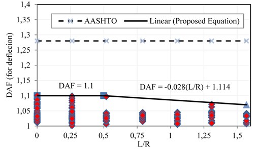
Fig. 7DAF related to support reaction versus L/R
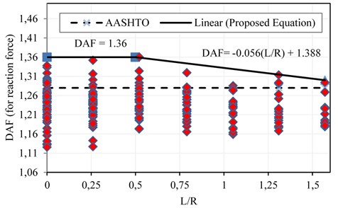
Regarding the dispersion of calculated DAF, the maximum values of the DAF should be considered to enhance safety. As a result, to estimate the maximum values of DAF, some straight lines are fitted to the upper bound of the DAFs calculated versus L/R values. The equations of fitted lines can be obtained as Eqs. (6) and (7). The DAF is a function of L/R in these equations. The DAF corresponded to maximum displacement is derived from the data points indicated in Fig. 6:
The DAF corresponded to maximum values of support reaction is derived from the data points shown in Fig. 7 as Eq. (7):
The DAF can be evaluated by means of above equations when the L/R related to a bridge ranges between 0 and 1.57. The magnitudes of DAF provided by AASHTO code are also compared with fitted lines in Figs. 6 and 7 (dash lines).
The results of the parametric study demonstrate that, in the investigated bridges, the magnitude of DAF presented by AASHTO code is overestimated in comparison with the DAF value related to displacement responses and the design is safe. However, it should be noted that the DAFs related to support reaction is greater than the values presented by AASHTO code. This can lead to underestimate the amount of IF calculated by AASHTO for supports and bridge bearings.
6. Damage detection
If one concentrated load with assumptions of Euler-Bernoulli has been located in point i of the beam, strain energy that is saved in the beam can be estimated as follow [21, 22]:
By assuming that the beam divides to several elements, strain energy in one element can be calculated as below:
where aj and aj+1 are the limit of the j element.
So, if the place that the static load works on moves forward with the constant step, the sum of strain energy in j element that is resulted from the moving load can be calculated as below:
Assuming the same distance between the points in the deformation vectors, the strain energy for one element is obtained from the following equation:
So if the dynamic effect of moving load on the beam has been considered, in j point the sum of potential and kinetic energy of the beam when the moving load crosses along it, is estimated as follow [23]:
where FS(ω) is Fourier Amplitude Spectrum and ω0 is the maximum frequency detected in the data (referred to as Nyquist frequency).
For identifying of damage in deck of bridge, the parameter taken from the definition of impact factor and response energy can be calculated as Dynamic Amplitude Factor of Energy (DAFE) like below:
When the structure experiences damage, Eq. (13) can be rewrite as below:
Which in this equation symbol (*) is related to damaging structure.
If in the structure has not been appeared any damages, so it can be write:
With respect to Eq. (15), the amount of DIE like Eq. (16) can be applied as an index to identify damage in each point. In Eq. (16), the second derivative of displacement vector has been calculated by central differences method [24]. How much the amount of DIE is close to one, the structure will be healthier:
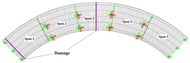
When features and geometry of materials and supporting condition of structural system change, structural damage will be defined [25]. The maximum deformation and bending moment due to passing vehicle along the bridge will happen in the middle of its span which this condition can increase the potential of vulnerability. On the other hand Fig. (7) shows that the impact factor from design codes compared to corresponding values that are related to supporting reaction of horizontally curved bridges are unreliable. So, in constructed bridges the possibility of damage in the middle and the places near the supports are more than other places. In this study two separate damages in deck with subtended angle that equals to 90 degrees have been considered. The places that damages have happened are located in 1.5 and 37.5 meter away from abutment (Fig. 8). Damage is defined as 40 % reduction of Young’s modulus.
Fig. 8The place of damage in horizontally curved bridge with a subtended angle of 90°
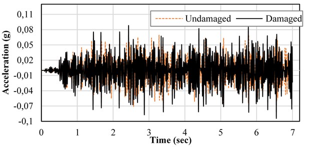
According to Table 4, maximum impact factor happens when the speed of truck is about 40 (km/h). By applying static and dynamic analysis of damaging bridge under moving load, deformation and acceleration response in the middle of first, second and third spans of the bridge are determined. Fig. 9 shows the static response of the displacement and Fig. 10 shows the dynamic response of the acceleration in the middle of the bridge deck.
Fig. 9Displacement static response in the middle of deck under moving load
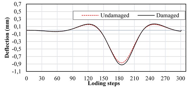
Fig. 10Acceleration dynamic response in the middle of deck under moving load
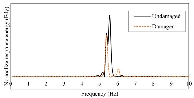
By using Eqs. (11) and (12), the changes of strain energy in structure (Fig. 11) and the energy that is resulted of acceleration response (Fig. 12) in the desired location on deck can be calculated respectively.
With respect to Eq. (18), DIM that is related to the points in the middle of first, second and third spans of bridge can be estimated 0.73, 0.68 and 0.56 respectively. These values show that this index can be used successfully to indicate damages on the deck of horizontally curved bridges.
Fig. 11The changes of strain energy in the middle of deck under moving load
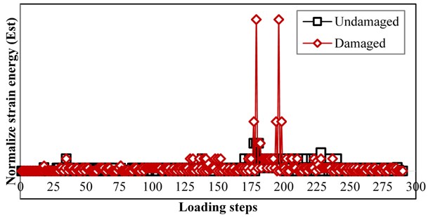
Fig. 12The changes of acceleration response energy in the middle of deck under moving load
7. Conclusions
In the present research work, a parametric study is conducted to examine the effects of vehicle speed as well as the ratio of arc length to arc radius, on IF value. A number of equations are presented by performing about 400 dynamic analyses as well as 400 static analyses to estimate IF of the horizontally curved bridges. The DAFs associated with the vertical displacement of the deck (Eq. (6)) and the support reaction (Eq. (7)) are derived dependent on L/R. The probable damage of the deck of concrete curved bridges is determined by Comparing of the impact factors obtained in this research to those suggested by AASHTO. To identify damage in existing bridges, in the early stages of damage, a new index (DIE) is developed based on the definition of dynamic amplification factor and deck response energy under the influence of standard truck Hs20-440. It is observed that the damage can be detected by determining variation of the strain energy of the bridge and the energy calculated from the FS(ω) of deck dynamic response on the middle of the span. The results of the studies are illustrated as follows:
1) The DAF associated with support reaction, which is obtained in this paper, is greater than the magnitudes presented by AASHTO code. Therefore, using AASHTO code to obtain the IF may lead to an underestimated design for the bridge supports and bearings.
2) The separation of the IF magnitude into DAFs related to displacement responses and support reaction enhances the designs safety and causes the designs to be more economical.
3) When the amount of L/R is less than 0.5, the DAF is a constant value and by increasing this proportion, the DAF decreases.
4) As vehicle speed increases, the DAF related to displacement increases.
5) The vehicle speed is inversely proportional to DAF associated with support reaction.
6) The effect of vehicle’s axle distance on the DAF is negligible.
7) The DIE index presented in the study is a suitable method for determining the damage to the deck.
The results obtained from this research work show that, the dynamic behavior of horizontally curved bridges has a lot of complexity and further studies are required in this field.
References
-
Manual H. S. American Association of State Highway and Transportation Officials. Washington, DC, Vol. 19192, 2010.
-
Fafard M., Laflamme M., Savard M., Bennur M. Dynamic analysis of existing continuous bridge. Journal of Bridge Engineering, Vol. 3, Issue 1, 1998, p. 28-37.
-
Zhang X., Sennah K., Kennedy J. B. Evaluation of impact factors for composite concrete-steel cellular straight bridges. Engineering Structures, Vol. 25, Issue 3, 2003, p. 313-321.
-
Hamidi S. A., Danshjoo F. Determination of impact factor for steel railway bridges considering simultaneous effects of vehicle speed and axle distance to span length ratio. Engineering Structures, Vol. 32, Issue 5, 2010, p. 1369-1376.
-
Huang D. Dynamic and impact behavior of half-through arch bridges. Journal of Bridge Engineering, Vol. 10, Issue 2, 2005, p. 133-141.
-
Senthilvasan J., Thambiratnam D. P., Brameld G. H. Dynamic response of a curved bridge under moving truck load. Engineering Structures, Vol. 24, Issue 10, 2002, p. 1283-1293.
-
Rezaiguia A., Ouelaa N., Laefer D. F., Guenfoud S. Dynamic amplification of a multi-span, continuous orthotropic bridge deck under vehicular movement. Engineering Structures, Vol. 100, 2015, p. 718-730.
-
Carrasco C. J., Osegueda R. A., Ferregut C. M., Grygier M. Damage localization in a space truss model using modal strain energy. Proceedings-SPIE the international society for optical engineering, 1997, p. 1786-1792.
-
Kim J.-T., Stubbs N. Model-uncertainty impact and damage-detection accuracy in plate girder. Engineering Structures, Vol. 121, Issue 10, 1995, p. 1409-1417.
-
Li H.-N., Li D.-S., Song G.-B. Recent applications of fiber optic sensors to health monitoring in civil engineering. Engineering Structures, Vol. 26, Issue 11, 2004, p. 1647-1657.
-
Moughty J. J., Casas J. R. A state of the art review of modal-based damage detection in bridges: development, challenges, and solutions. Applied Sciences, Vol. 7, Issue 5, 2017, p. 510.
-
Jelodarian H. Seismic Modal Analysis of Horizontally Curved Bridge. Imam Khomeini International University, Qazvin, 2006.
-
Bayat M., Daneshjoo F., Nisticò N. Probabilistic sensitivity analysis of multi-span highway bridges. Steel and Composite Structures, Vol. 19, Issue 1, 2015, p. 237-262.
-
Bayat M., Daneshjoo F., Nisticò N. A novel proficient and sufficient intensity measure for probabilistic analysis of skewed highway bridges. Structural Engineering and Mechanics, Vol. 55, Issue 6, 2015, p. 1177-1202.
-
Bayat M., Daneshjoo F., Nisticò N. The effect of different intensity measures and earthquake directions on the seismic assessment of skewed highway bridges. Earthquake Engineering and Engineering Vibration, Vol. 16, 2017, p. 165-179.
-
Bayat M., Daneshjoo F. Seismic performance of skewed highway bridges using analytical fragility function methodology. Computers and Concrete, Vol. 16, Issue 5, 2015, p. 723-740.
-
Karoumi R. Response of Cable-Stayed and Suspension Bridges to Moving Vehicles: Analysis Methods and Practical Modeling Techniques. KTH Royal Institute of Technology, 1998.
-
Geometric design standards for Ontario highways. Ontario Ministry of Transportation, Downsview, Ontario, Canada, 1994.
-
Yang Y.-B., Yau J. D., Yao Z., Wu Y. S. Vehicle-Bridge Interaction Dynamics: with Applications to High-Speed Railways. World Scientific, 2004.
-
Broquet C. Dynamic Behavior of Deck Slabs of Concrete Bridges under Road Traffic. EPFL University, Lausanne, 1999.
-
Carden E. P., Fanning P. Vibration based condition monitoring: a review. Structural Health Monitoring, Vol. 3, Issue 4, 2004, p. 355-377.
-
Humar J., Bagchi A., Xu H. Performance of vibration-based techniques for the identification of structural damage. Structural Health Monitoring, Vol. 5, Issue 3, 2006, p. 215-241.
-
Daneshjoo F. Fundamentals of Earthquake Engineering and Risk Analysis. Danesh-e-Farda Press, Tehran, Iran, 1999, (in Persian).
-
Cruz P. J. S., Salgado R. Performance of vibration-based damage detection methods in bridges. Computer-Aided Civil and Infrastructure Engineering, Vol. 24, 2008, p. 62-79.
-
Than Soe M. Vibration-Based Finite Element Model Updating and Structural Damage Identification. University of Greenwich, 2013.

