Abstract
Using the equation of displacement compatibility, a novel method for describing the contact between pantograph and catenary is proposed in this paper. Then an interaction catenary-pantograph system capable of describing vertical vibration is established. Taking into account the frictional characteristic between pantograph and catenary, the Coulomb model is applied. Based on the continuum mechanics, the partial differential equations of the coupling system are set up. For facilitating numerical simulation, the dynamic equations are further discretized by the Galerkin method, in which the modes of the complicated system are obtained by the finite element method. Therefore, the ordinary differential equations of the coupling system are numerically solved and the corresponding dynamic behaviors at different running speeds are analyzed in terms of waveform. Moreover, the effects of the frictional characteristic on the contact force between pantograph and catenary are discussed in detail. By comparing the results with European standard EN50318, the novel contact method is proved to be valid and accurate.
1. Introduction
As a high-efficiency, low-consumption and reliable transportation means, high speed railway is widely used and rapidly developed around the world, particularly in the Eurasia. Pantographs are mounted on the top of trains for collecting electric power from the catenary to provide traction for operation of the high-speed trains. During the running process, the uplift force acted on the pantograph ensures the contact between pantograph and catenary for the continuous power supply. Under this circumstance, the interactional oscillation of the pantograph-catenary system will occur. Unfortunately, higher speed increases susceptibility to serious oscillation, which causes the component wear, collect quality decrease and even contact loss [1]. It is evident that analyzing the interactional vibration mechanism of the pantograph-catenary system is one of the major concerns in the research field of pantograph-catenary interaction.
Dynamic modeling of pantograph-catenary system includes three primary aspects, i.e., catenary modeling, pantograph modeling, and contact modeling of pantograph-catenary. In the past researches, the catenary is usually simplified as two Euler-Bernoulli beams and the pantographs are usually simplified as spring-damping-mass structures, which are the so called lumped mass models. Meanwhile, the contact is usually described by the penalty function method and the numerical simulation is conducted by the Newmark-β, Runge-Kutta, and so on. Ockendon and Tayler [2] built the dynamic model of single overhead trolley wire suspended at equal intervals by stiff springs with a uniform motion pantograph, and then analyzed the motion of the model. To simulate the vertical motion of pantograph-catenary system, Arnold et al. [3] proposed a more accurate approach, in which the finite difference method was applied to discretize the partial differential equations of motion in space and the typical DAE techniques were applied to solve the ordinary differential equations. For facilitating the analytical investigation, Wu et al. [4, 5] considered the pantograph-catenary system as a time-varying single degree-of-freedom system, in which the overhead wire system was represented as an infinite periodically spring-supported string. On this basis, they studied the stability and the dynamic behavior of the single degree-of-freedom system.
With the rapid development of numerical simulation, the finite element method is widely used in the field of catenary modeling [6-9]. Considering the contact element by penalty method, Collina et al. [10] proposed an improved pantograph-catenary model, which included the finite element model of catenary with nonlinear element droppers and the lumped mass pantograph with the bending deformation of the collector heads by a modal superposition approach. Park et al. [11] optimized the design parameters of the pantograph by analyzing the dynamic behavior of the pantograph-catenary system. In order to solve the long time-consuming caused by the finite element method, Zhang and Mei et al. [12-14] proposed a hybrid method with finite element method and mode superposition technique to reduce the numbers of the motion equations and studied the influence of the overlap span on the interaction dynamic behaviors of pantograph-catenary system. In the reference [15], a mathematical model of catenary-pantograph system was developed to study the dynamic interaction of the catenary spans where the transition spans were overlapped. Song et al. [16] developed a modeling approach based on the analytical expressions of nonlinear cable and truss elements which could describe the intrinsic nonlinear characteristics and complicated structure of high-speed catenary.
In order to simulate the actual structure of pantograph-catenary more accurately, the dynamic models of catenary, pantograph and contact gradually are becoming more precise. By using the absolute nodal coordinates of large deformation and the reference coordinates of rigid body, a precise dynamic model of pantograph-catenary system was established, where the pantograph was described by the multi-body and the flexible catenary was described by the nonlinear continuous beam [17-20]. According to the Hertz contact theory, Rauter et al. [21, 22] further achieved the integrated methodology to represent the contact between the finite element model of catenary and multi-body model of pantograph. In the reference [23], an improved stiffness model was used to calculate the catenary stiffness and the Lagrange multipliers was used to describe the contact during the modeling process of the simplified catenary-pantograph system. A hybrid simulation methodology called the ‘Hardware-in-the-loop’ in which a physical pantograph was set in interaction with a numerical model of the catenary which was ran in real time was proposed by Facchinetti [24]. Except for the classical methods, the above research works provided some other novel and efficient means for analyzing the dynamic characteristic of the pantograph-catenary system.
Additionally, some professional software is developed to simulate the static and dynamic behaviors of the pantograph-catenary system, such as the PrOSA by Deutsche Bahn AG, the PantoCat by Instituto Superior Tecnico Lisboa, the PCRUN by Southwest Jiaotong University [25-27]. As a synthetic comparison of the simulation software from ten institutes in different countries, reference [28] pointed out the similarities and differences in the modeling approaches and gave a comprehensive presentation of the simulation results.
As one of the crucial steps during the modeling process, the contact model is usually defined by the penalty method in the existing works. Due to the reason that there is no specific method for calculating the contact stiffness in the penalty method, the stiffness is treated as an empirical coefficient, which may cause the inaccurate simulation results. Therefore, the characterization of contact between pantograph and catenary is of practical significance.
In view of this case, a novel method for describing the contact of pantograph-catenary is proposed by using the equation of displacement compatibility in this paper. Furthermore, the friction between pantograph head strip and contact wire is considered and described by the Coulomb model. Then a coupling dynamic model of pantograph-catenary is established and the corresponding dynamic characteristic is analyzed. Meanwhile, the effects of relevant parameters on the vibration response and contact force of the system are discussed.
2. Mathematical formulation
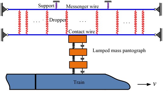
In the actual railway system, there are three main types of catenary suspension structure, including simple catenary suspension, elastic catenary suspension and complicated catenary suspension. In this paper, a simple catenary suspension is considered and a coupling system of simple catenary and lumped mass pantograph is established, as shown in Fig. 1. The catenary model refers to the middle spans of one anchor span in which the overlapping span is neglected. Besides, the straight line is considered here instead of a curve line.
Fig. 1Schematic diagram of simple catenary- lumped mass pantograph system
2.1. Simple catenary model
The vibration equations of the simple catenary model are derived in this section. As shown in Fig. 2, the simple catenary model is mainly composed of messenger wires, contact wires and droppers. According to the mechanical characteristics of the parts above, the messenger wires and contact wires are described by the simple supported Euler-Bernoulli beams. The droppers are simplified as the nonlinear springs, whose tension stiffness is far greater than the compression stiffness. The messenger wires are suspended by the springs at supports.
Fig. 2Schematic diagram of simple catenary model
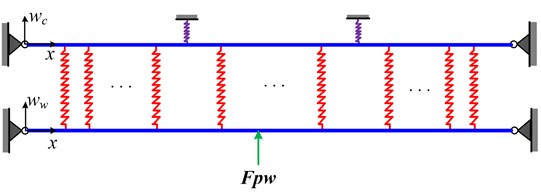
On the basis of the infinitesimal method in the continuum mechanics, the vertical vibration equation of the messenger wire can be expressed as:
where wc denotes the vertical displacement of the messenger wire, ρc denotes the density of messenger wire, Ac denotes the cross area of the messenger wire, Cc denotes the structural damping, EIc denotes the bending stiffness, Tc denotes the tensile force acted on the messenger wire, Fc,i includes the elastic force and gravity of the ith dropper.
It can be seen from Fig. 2 that the messenger wire is suspended by the supports which are modeled as springs. Therefore, the elastic force caused by the ith support can be written as:
where kz denotes the suspension stiffness, wc,z,i denotes the vertical displacement of the catenary at the ith support, δ is the Dirac function, xz,i is the location of ith support on the axis x.
Similarly, the vertical vibration equation of the contact wire is:
where the subscript w denotes the parameters or variables of contact wire, Fpw is the contact force of pantograph head acted on the contact wire, v is the running speed of the train.
The forces of the droppers, which are used to suspend the contact wire on the messenger wire, can be expressed as:
where xi denotes the location of ith dropper on the axis x, md,i denotes the mass of ith dropper and clamp, f0,i is the pre-tension of dropper due to the pre-sag caused by the self-weight of the catenary.
Meanwhile, the expression of fd,i satisfies:
where and denote the tensile and compression stiffness of the droppers, respectively. denotes the initial elongation of th dropper caused by the pre-sag. denotes the vertical displacement of messenger wire at the location of th dropper, and denotes the vertical displacement of contact wire at the location of th dropper.
2.2. Lumped mass pantograph model
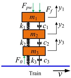
It can be seen from Fig. 3 that pantograph model is composed of lumped masses, linear springs and dampers. According to the Newton’s second law, the vibration equations of lumped mass model of pantograph without car-body can be written as:
where is the static uplift force and is the equivalent vertical force from the frictional force. Please note that the actual pantograph includes a series of articulated bar linkages. Therefore, although the frictional force acted on the pantograph head is longitudinal, the moment caused by the frictional force is able to affect the vertical vibration of the pantograph. The specific equivalent process of is presented in Section 2.4.
Fig. 3Lumped mass pantograph model
2.3. Pantograph-catenary contact model
When the loss of contact does not happen, the interaction of catenary and pantograph is achieved by the contact force , as depicted in Eqs. (1-7). In this condition, the vertical displacement of pantograph head is equal to that of contact point on the contact wire, namely:
In which is the running speed of the train.
Taking the derivative of Eq. (8) with respect to time , the additional constraint condition of velocity and acceleration can be obtained, respectively:
According to Eqs. (8-10), Eq. (7) can be further written as:
By substituting the expression of obtained from the first equation of Eq. (11) into Eq. (3), the vibration equations of the pantograph-catenary system without loss of contact obey:
Then the dynamic responses of catenary and lumped mass pantograph can be obtained by numerically integrating of Eq. (12). Meanwhile, the displacement, velocity and acceleration of pantograph head can be obtained from Eqs. (8-10). Combining the vibration displacement of catenary with that of pantograph, the contact force can be further calculated in Eq. (11).
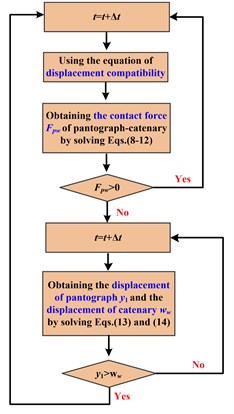
As illustrated in Eqs. (9-10), when the pantograph head keeps contact with the catenary, the velocities and accelerations of pantograph head may not be uniform with that of contact point of contact wire. Thus, these phenomena may lead to the occurrence of loss of contact. Dealing with such complicated contact problem, the judgment for loss of contact is essential at every time step during the numerical integration.
Let us define the ()th time step and th time step as and , respectively. If loss of contact does not occur at , the criterion of loss of contact depends on the sign of . For the case of , the loss of contact between catenary and pantograph does not happen at . Otherwise, the loss of contact occurs and then the coupling system of catenary-pantograph is decomposed into two independent systems at .
At this moment, the vibration equations of independent catenary turn out to be:
And the vibration equations of independent pantograph are:
If loss of contact is recognized at , namely 0, the relative value of and is used to identify the loss of contact at instead of . If is satisfied, the pantograph resumes contact with the contact wire. Otherwise, the loss of contact remains. The detailed recognition process of loss of contact is depicted in Fig. 4.
Fig. 4Recognition process of pantograph-catenary contact
Compared with the traditional contact model, the advantage of the novel contact method is the application of displacement compatibility equations which can avoid the determination of the contact stiffness so as to improve the calculation accuracy to some extent.
2.4. Frictional model for catenary-pantograph
During the operation process of train, the strips of pantograph head move along the contact wire, which causes the sliding friction. Thus, the Coulomb model is used to describe the frictional characteristic, namely:
where denotes the Coulomb frictional coefficient of strip-contact wire.
Although the direction of frictional force is longitudinal, the moment generated by the frictional force would actually affect the vertical vibration of pantograph-catenary system. In the view of this point, the detailed illustration of the effect of frictional force is introduced in this section.
Similar with the frictional force in this paper, some of the aerodynamic forces acted on the pantograph are also longitudinal in reference [29]. Under the action of aerodynamic force, a vertical constraint is added on the top of the upper arm and the corresponding constraint force is calculated. According to the principle of vertical static balance, the constraint force and uplift force are equal in magnitude and opposite in direction. Therefore, the equivalent process from aerodynamic force to uplift force is accomplished.
Based on the principle of virtual work, another method for estimating the uplift force is provided in the reference [30]. However, the research object mentioned in the above two papers is a single-degree-of-freedom pantograph system with articulated frame and the deflection of the pantograph head suspension is neglected.
Fig. 5Schematic diagram of pantograph frame
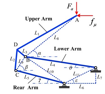
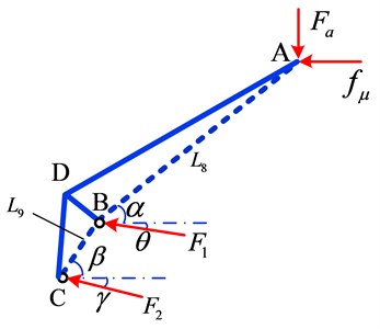
Fig. 6Force analysis of pantograph upper arm
Using the particular equivalent method mentioned in the reference [29], the longitudinal frictional force is converted to the vertical uplift force, which acts on the pantograph head. The single-degree-of-freedom pantograph system with articulated frame is shown in Fig. 5, in which is the only degree-of-freedom known as the rising angle of pantograph. , , can be expressed by the relative location and geometric characteristics of and the length of arms. The detailed derivations of geometric relations are illustrated in appendix.
Fig. 6 shows the force analysis of the upper arm, where denotes the constraint force, denotes the frictional force when the pantograph runs with opening stomata, and denote the internal force of lower arm and lower link, respectively. Therefore, the equations of static equilibrium can be expressed as:
Referring to Eq. (15), the relation between and can be obtained by solving Eq. (16), so that:
where and respectively obey:
And:
is called the transfer coefficient. When the pantograph runs with closing stomata, the direction of frictional force is reversed:
3. Discretization of simple catenary model
In this section, the Galerkin method is used to discretize the partial differential equations of catenary. During the discretization, the main vibration mode functions are essential and should satisfy the boundary conditions of catenary. According to the mechanics of vibration, the solutions of vibration equations of catenary can be expressed as:
where and are the assumed mode, and are the mode coordinates of messenger wire and contact wire, is the modal truncation order, respectively.
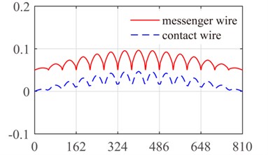
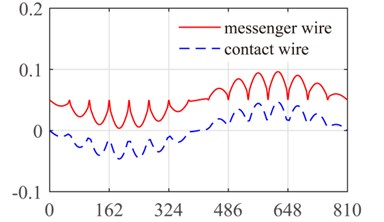
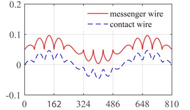
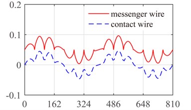
According to the references [28, 31], the structure parameters of catenary are shown in Table 1. The span of the catenary is 15 and the dropper position vector in each span is [3.375 10.125 16.875 23.625 30.375 37.125 43.875 50.625] (m). For each dropper, the tensile stiffness is 106 N/m and the compressive stiffness is generally in 1/100 order of magnitude with tensile stiffness [31]. Obviously, the main mechanical characteristic of dropper is tensile strength rather than compressive strength. Additionally, the stiffness of messenger wire suspension is 0.5×10⁶ N/m. Since the catenary structure is relatively complicated, the analytical expressions of mode functions can hardly be derived. Therefore, the finite element method is applied to obtain the numerical mode functions of catenary by modal analysis. It can be seen from Fig. 7 that the first four modes are exhibited with bending vibration.
Table 1Parameters of catenary model
Physical parameter | Messenger wire | Contact wire |
Tensile force (N) | 14000 | 20000 |
Linear density (kg/m) | 0.605 | 1.33 |
Length of one span l (m) | 54 | 54 |
Damping coefficient (N.s/m) | 0.03 | 0.03 |
Substitute Eqs. (21-22) into Eq. (12) and Eq. (13), then multiply both sides of the equations by and and take the integration of the equations with respect to at the interval and .
Based on the above steps, the ordinary differential equations can be obtained and written in matrix form as:
where is the mass matrix, is the damping matrix, is the stiffness matrix, is the discretized force vector, is the modal coordinates vector.
Fig. 7The first four modes of the ten-span catenary: a) first mode, b) second mode, c) third mode and d) fourth mode
a)
b)
c)
d)
4. Verification of contact model for catenary-pantograph
In order to examine the validity of contact model, the verification is conducted referring to the European standard EN50318. The reference model, which includes a ten-span catenary and a binary-lumped-mass pantograph, is considered in the EN50318. Meanwhile, the running speed is set to 250 km/h and 300 km/h, respectively. In order to reduce the effects of initial condition and system boundary on the numerical results, the 5th and 6th spans are selected for analyzing the contact force and vibration response.
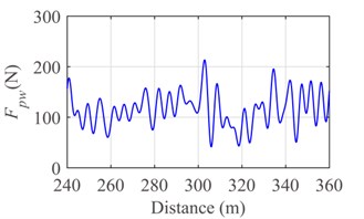
The statistical results of pantograph-catenary system and the European standard EN50318 are shown in Table 2. The simulation results in this paper are within the allowance of EN50318, including the mean contact force, standard deviation and so on. Therefore, the novel contact model is proved to be valid.
Table 2Comparison of simulation results in this paper and EN50318 reference model
Statistical index | This paper ( 300 km/h) | EN50318 ( 300 km/h) | This paper ( 250 km/h) | EN50318 ( 250 km/h) |
Mean contact force (N) | 115.85 | 110-120 | 117.41 | 110-120 |
Standard deviation (N) | 32.84 | 32-40 | 26.33 | 26-31 |
Max. statistic value (N) | 214.37 | 210-230 | 196.4 | 190-210 |
Min. statistic value (N) | 17.33 | -5-20 | 38.42 | 20-40 |
Max. real value (N) | 213.47 | 190-225 | 181.95 | 175-210 |
Min. real value (N) | 41.48 | 30-55 | 57.58 | 50-75 |
Max. uplift at support (mm) | 61.77 | 55-65 | 54.5 | 48-55 |
Percentage of the loss of contact (%) | 0 | 0 | 0 | 0 |
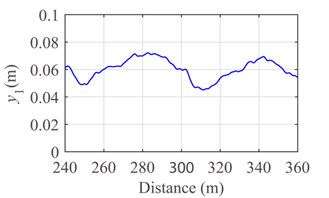
Fig. 8Response of the pantograph-catenary system at the speed v= 300 km/h: a) contact force, b) displacement of pantograph head and c) displacement of support
a)
b)
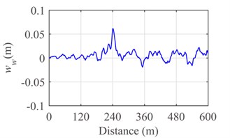
c)
Fig. 9Response of the pantograph-catenary system at the speed v= 250 km/h: a) contact force, b) displacement of pantograph head and c) displacement of support
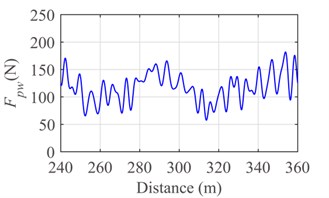
a)
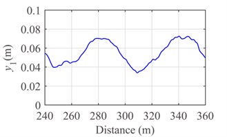
b)
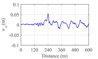
c)
Fig. 8 and Fig. 9 show the contact force, displacement of pantograph head, and uplift of contact wire at support at the running speed 300 km/h and 250 km/h, respectively. By comparing Fig. 8 with Fig. 9, it is evident that the contact of pantograph-catenary becomes serious and the vibration displacement of pantograph head gradually becomes intense with the increase of running speed. In addition, the uplift displacement of support achieves the maximum value at 240 m when the running speed is 250 km/h or 300 km/h.
5. Results and discussions
By the Runge-Kutta method, the dynamic characteristic of the pantograph-catenary system is numerically analyzed. It should be emphasized that, during the integration process, the contact status of pantograph-catenary and the slacken status of dropper need to be judged in every time step.
5.1. Dynamic characteristics of a catenary-pantograph system
After verifying the contact model proposed in this paper, the dynamic characteristic of pantograph-catenary system shown in Figs. 2-3 is further analyzed in this section.
According to reference [31], the structure parameters of lumped mass model and frame model for pantograph are shown in Table 3 and Table 4, respectively. The parameters of catenary model illustrated in Table 1 remain unchanged.
Table 3Structure parameters of lumped mass model for pantograph
Physical parameter | Value |
, , (kg) | 8.5, 4.63, 4.8 |
, , (N/m) | 6045, 5400, 1 |
, , (N.s/m) | 10, 5, 32 |
(N) | 152 |
Table 4Structure parameters of frame model for pantograph
Physical parameter | Value | Physical parameter | Value |
(mm) | 2006 | (mm) | 247 |
(mm) | 104 | (mm) | 1640 |
(mm) | 1382 | (mm) | 128 |
(mm) | 467 | (rad) | 1.35 |
(rad) | 1.04 |
Based on the above analysis in Section 2.4, the running direction of pantograph (opening and closing stomata), rising angle of pantograph and frictional coefficient are the principal factors for determining the uplift force.
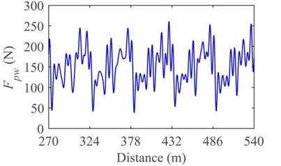
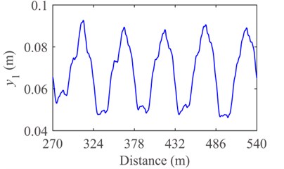
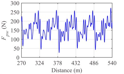
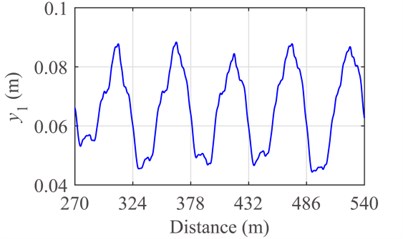
In order to study the effects of frictional force on the dynamic characteristic of pantograph-catenary system, three cases of friction are conducted, including opening stomata (with frictional force), closing stomata (with frictional force) and no frictional force. Keeping the other parameters constant, the rising angle is set to 45°, running speed v is set to 300 km/h, frictional coefficient is set to 0.3 [32].
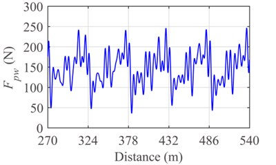
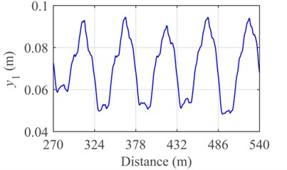
By the Runge-Kutta method, the numerical results of the 6th-10th spans in the fifteen-span catenary are obtained and filtered in the frequency range of [0, 20] (Hz). The contact forces and vibration displacements of pantograph head in the three cases of friction are shown in Figs. 10-12. The maximum value, minimum value, mean value, standard deviation of contact force, and displacement of pantograph head are shown in Table 5 and Table 6, respectively.
To some extent, the frictional force can affect the dynamic characteristics of the pantograph-catenary system. The mean values and standard deviations of contact force and pantograph head displacement in the condition of opening stomata with a rising angle of 45° are larger than that in the condition of no frictional force. The main reason lies in that, for the case of opening stomata with a rising angle of 45°, the direction of moment caused by frictional force is in accordance with that of rising moment. In other words, the equivalent uplift force generated by the frictional force enhances the interaction between pantograph and catenary under the condition of opening stomata with a rising angle of 45°.
On the contrary, the mean values and standard deviations of contact force and pantograph head displacement in the condition of closing stomata with a rising angle of 45° are less than that in the condition of no frictional force. When the direction of moment caused by frictional force is opposite to that of rising moment, the equivalent uplift force weakens the interaction between pantograph and catenary.
Fig. 10Response of the pantograph-catenary system without friction: a) contact force and b) displacement of pantograph head
a)
b)
Fig. 11Response of the pantograph-catenary system with friction and opening stomata: a) contact force and b) displacement of pantograph head
a)
b)
Fig. 12Response of the pantograph-catenary system with friction and closing stomata: a) contact force and b) displacement of pantograph head
a)
b)
Table 5Statistics of contact force of pantograph Fpw
Statistical index | Contact force without friction | Opening stomata, contact force with friction | Closing stomata, contact force with friction |
Max. real value (N) | 260.66 | 272.6 | 246.3 |
Min. real value (N) | 38.30 | 26.12 | 36.25 |
Mean value (N) | 151.39 | 157.9 | 146.9 |
Standard deviation (N) | 43.43 | 45.4 | 40.54 |
Table 6Statistics of displacement of pantograph y1
Statistical index | Displacement without friction | Opening stomata, displacement with friction | Closing stomata, displacement with friction |
Max. real value (m) | 0.093 | 0.095 | 0.089 |
Min. real value (m) | 0.046 | 0.048 | 0.044 |
Mean value (m) | 0.068 | 0.071 | 0.066 |
Standard deviation (m) | 0.014 | 0.014 | 0.014 |
5.2. Analysis of varying parameters
Experimental results [32, 33] show that, at the speed of 140-170 km/h, the frictional coefficient between carbon strip and copper contact wire varies from 0.24 to 0.35 in the condition of alternating current of 0-240 A. Besides, the frictional coefficient increases slightly with the increase of sliding velocity and decreases slightly with the increasing of local temperature.
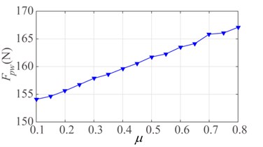
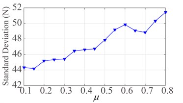
Fig. 13Effect of frictional coefficient μ: a) mean contact force and b) standard deviation
a)
b)
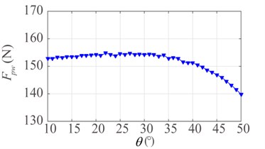
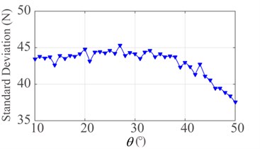
Fig. 14Effect of rising angle θ: a) mean contact force and b) standard deviation
a)
b)
Therefore, the effect of frictional coefficient on the contact force needs to be discussed in detail. The variation of frictional coefficient is set to 0.1-0.8. As shown in Fig. 13, when the pantograph runs at the speed of 300 km/h with closing stomata, the mean value and standard deviation of contact force increase gradually with the increase of frictional coefficient.
Furthermore, the relation between mean value and standard deviation of contact force and rising angle is shown in Fig. 14, in which the variation of rising angle is set to 10°-50°. It is evident that the mean value and standard deviation of contact force increase slightly in the range of 10°-25°. However, they decrease with the increase of rising angle in the range of 25°-50°.
The above phenomena suggest that the friction of pantograph-catenary can not only intensify the wear between pantograph head strip and contact wire, but also directly affect the dynamic interaction of pantograph-catenary.
6. Conclusions
In this paper, a novel contact model between pantograph and catenary has been proposed by using the displacement compatibility. Based on the contact force model and the Coulomb frictional model, the vertical dynamic characteristic of pantograph-catenary system has been investigated. Meanwhile, the effects of frictional coefficient and rising angle have been discussed. According to the numerical results, the following conclusions can be obtained:
1) By comparing with the European standard EN50318, the contact model is proved to valid and accurate.
2) Reducing the friction between pantograph and catenary can not only reduce the wear of components but also effectively enhance the performance of coupling system.
3) The dynamic characteristic of pantograph-catenary system is partly determined by the rising angle.
This work can enrich our understanding to the mechanical mechanism of contact between pantograph and catenary, and may promote the investigation of pantograph-catenary.
References
-
Poetsch G., Evans J., MeisingerR., Kortüm W., Bauldauf W., Veitl A., Wallaschek J. Pantograph/Catenary dynamics and control. Vehicle System Dynamics, Vol. 28, Issue 2, 1997, p. 159-195.
-
Ockendon J. R., Tayler A. B. The dynamics of a current collection system for an electric locomotive. Proceedings of the Royal Society of London, Vol. 332, Issue 1551, 1971, p. 447-468.
-
Arnold M., Simeon B. Pantograph and catenary dynamics: a benchmark problem and its numerical solution. Applied Numerical Mathematics, Vol. 34, Issue 4, 2002, p. 345-362.
-
Wu T. X., Brennan M. J. Basic Analytical study of pantograph-catenary system dynamics. Vehicle System Dynamics, Vol. 30, Issue 6, 1998, p. 443-456.
-
Wu T. X., Brennan M. J. Dynamic stiffness of a railway overhead wire system and its effect on pantograph-catenary system dynamics. Journal of Sound and Vibration, Vol. 219, Issue 3, 1999, p. 483-502.
-
Haritos N., He D. T. A finite element formulation for cables suitable for dynamic modelling. Mathematics and Computers in Simulation, Vol. 32, Issues 1-2, 1990, p. 179-184.
-
Lesser M., Karlsson L., Drugge L. An interactive model of a pantograph-catenary system. Vehicle System Dynamics, Vol. 25, Issue 1, 1996, p. 397-412.
-
Schaub M., Simeon B. Pantograph-catenary dynamics: an analysis of models and simulation techniques. Mathematical and Computer Modelling of Dynamical Systems, Vol. 7, Issue 2, 2001, p. 225-238.
-
Zhou N., Zhang W. H. Investigation on dynamic performance and parameter optimization design of pantograph and catenary system. Finite Elements in Analysis and Design, Vol. 47, Issue 3, 2011, p. 288-295.
-
Collina A., Bruni S. Numerical simulation of pantograph-overhead equipment interaction. Vehicle System Dynamics, Vol. 38, Issue 4, 2002, p. 261-291.
-
Park T. J., Han C. S., Jang J. H. Dynamic sensitivity analysis for the pantograph of a high-speed rail vehicle. Journal of Sound and Vibration, Vol. 266, Issue 2, 2003, p. 235-260.
-
Zhang W. H., Mei G.M., Wu X. J., Shen Z.Y. Hybrid simulation of dynamics for the pantograph-catenary system. Vehicle System Dynamics, Vol. 38, Issue 6, 2002, p. 393-414.
-
Mei G. M., Zhang W. H., Zhao H. Y., Zhang L. M. A hybrid method to simulate the interaction of pantograph and catenary on overlap span. Vehicle System Dynamics, Vol. 44, Issue 1, 2006, p. 571-580.
-
Zhang W. H., Liu Y., Mei G.M. Evaluation of the coupled dynamical response of a pantograph-catenary system: contact force and stresses. Vehicle System Dynamics, Vol. 44, Issue 8, 2006, p. 645-658.
-
Benet J., Alberto A., Arias E., Rojo T. A Mathematical Model of the Pantograph-Catenary Dynamic Interaction with Several Contact wires. IAENG International Journal of Applied Mathematics, Vol. 37, Issue 2, 2007, p. 136-144.
-
Song Y., Liu Z. G., Wang H. R., Lu X. B., Zhang J. Nonlinear modelling of high-speed catenary based on analytical expressions of cable truss elements. Vehicle System Dynamics, Vol. 53, Issue 10, 2015, p. 1455-1479.
-
Seo J. H., Sugiyama H., Shabana A. A. Three-dimensional large deformation analysis of the multibody pantograph/catenary system. Nonlinear Dynamics, Vol. 42, Issue 2, 2005, p. 199-215.
-
Seo J. H., Kim S. W., Jung I. H., Park T. W., Mok J. Y., Kim Y. G., Chai J. B. Dynamic analysis of a pantograph-catenary system using absolute nodal coordinates. Vehicle System Dynamics, Vol. 44, Issue 8, 2006, p. 615-630.
-
Gerstmayr J., Shabana A. A. Analysis of thin beams and cables using the absolute nodal co-ordinate formulation. Nonlinear Dynamics, Vol. 45, Issue 1, 2006, p. 109-130.
-
Sugiyama H., Escalona J. L., Shabana A. A. Formulation of three-dimensional joint constraints using the absolute nodal coordinates. Nonlinear Dynamics, Vol. 31, Issue 2, 2003, p. 167-195.
-
Rauter F. G., Pombo J., Ambrósio J., Pereira M. Multibody modeling of pantographs for pantograph-catenary interaction. IUTAM Symposium on Multiscale Problems in Multibody System Contacts, Vol. 1, 2007, p. 205-226.
-
Rauter F. G., Pombo J., Ambrósio J., Chalansonnet J., Bobillot A., Pereira M. S. Contact model for the pantograph-catenary interaction. Journal of System Design and Dynamics, Vol. 1, Issue 3, 2007, p. 447-457.
-
Lopez-Garcia O., Carnicero A., Marono J. L. Influence of stiffness and contact modelling on catenary-pantograph system dynamics. Journal of Sound and Vibration, Vol. 299, Issues 4-5, 2007, p. 806-821.
-
Facchinett A., Bruni S. Hardware-in-the-loop hybrid simulation of pantograph-catenary interaction. Journal of Sound and Vibration, Vol. 331, Issue 12, 2012, p. 2783-2797.
-
Ambrósio J., Pombo J., Antunes P., Pereira M. PantoCat statement of method. Vehicle System Dynamics, Vol. 53, Issue 3, 2015, p. 314-328.
-
Massat J. P., Laine J. P., Bobillot A. Pantograph-catenary dynamics simulation. Vehicle System Dynamics, Vol. 44, Issue 1, 2006, p. 551-559.
-
Cho Y. H. Numerical simulation of the dynamic responses of railway overhead contact lines to a moving pantograph, considering a nonlinear dropper. Journal of Sound and Vibration, Vol. 315, Issue 3, 2008, p. 433-454.
-
Bruni S., Ambrósio J., Carnicero A., Cho Y. H., Finner L., Ikeda M., Kwon S.Y., Massat J. P., Stichel S., Tur M., Zhang W. H. The results of the pantograph-catenary interaction benchmark. Vehicle System Dynamics, Vol. 53, Issue 3, 2015, p. 412-435.
-
Li R. P., Zhou N., Zhang W. H., Mei G. M., Chen Z. B. Calculation and analysis of pantograph aerodynamic uplift force. Journal of the China Railway Society, Vol. 34, Issue 8, 2012, p. 26-32, (in Chinese).
-
Carnevale M., Facchinetti A., Maggiori L., Rocchi D. Computational fluid dynamics as a means of assessing the influence of aerodynamic forces on the mean contact force acting on a pantograph. Proceedings of Institution of Mechanical Engineers Part F-Journal of Rail and Rapid Transit, Vol. 230, Issue 7, 2016, p. 1698-1713.
-
Ambrósio J., Pombo J., Pereira M., Antunes P., Mósca A. Recent developments in pantograph-catenary interaction modelling and analysis. International Journal of Railway Technology, Vol. 1, Issue 1, 2012, p. 249-278.
-
Ding T., Chen G. X., Wang X., Zhu M. H., Zhang W. H., Zhou W. X. Friction and wear behavior of pure carbon strip sliding against copper contact wire under AC passage at high speeds. Tribology International, Vol. 44, Issue 4, 2011, p. 437-444.
-
Ding T., Chen G. X., Bu J., Zhang W. H. Effect of temperature and arc discharge on friction and wear behaviours of carbon strip/copper contact wire in pantograph-catenary systems. Wear, Vol. 271, Issues 9-10, 2011, p. 1629-1636.
Cited by
About this article
This work was supported by the National Nature Science Foundation of China (Grant No. 11372258).

