Abstract
In order to reveal the bifurcation mechanism and optimize the system design for high-static-low-dynamic-stiffness (HSLDS) vibration isolation system (VIS) with elastic base, the local bifurcation analyses both in unfolding parameter space and physical parameter space were carried out theoretically and numerically. Firstly, the restoring force of the HSLDS-VIS was approximated to linear and cubic stiffness by applying the Maclaurin series expansion and the motion equations of HSLDS-VIS with elastic base were established. Subsequently, the motion equations of HSLDS-VIS with elastic base were formulated to transform the system into a standard form and the averaging method was applied to obtain the single-variable bifurcation equation for the HSLDS-VIS with elastic base in case of primary resonance and 1:2 internal resonance. Furthermore, the transition sets and bifurcation diagrams in the unfolding parameter space were studied by means of singularity theory. Finally, for the engineering application, the transition sets were transferred back to the physical parameter space, thus to obtain the bifurcation diagrams of the amplitude with respect to the external force. The numerical simulation results show that the local bifurcations of HSLDS-VIS with elastic base in case of 1:2 internal resonance are considerable complex and need to be analyzed in six two-parameters spaces, meanwhile, the necessary condition of multiple solutions lies in some physical parameters, which can provide a theoretical basis and reference for design and application of the HSLDS-VIS with elastic base.
1. Introduction
Undesirable vibration can affect human comfort and even the structural safety, which has become an urgent problem to be solved in engineering. It is evident that the bandwidth of vibration isolation is often limited by the mount stiffness element required to support a static load. To overcome this limitation, the high-static-low-dynamic-stiffness (HSLDS) mechanism is put forward, what results in low natural frequency with a small static displacement. Whilst it maintains locally low stiffness near equilibrium and static load bearing, which reduces the natural frequency and extends the frequency isolation region [1]. The isolation system with HSLDS characteristic has been well established both theoretically and experimentally in recent literatures and has recently been the subject of growing interest of both engineers and researchers. Carrella et al. and Wu et al. investigated vibration isolators with HSLDS property via the combination of a mechanical spring and magnets [2, 3], Li et al. presented a device using a magnetic spring combined with rubber membranes to suppress vibration [4], Zhou et al. develop a tunable isolator with HSLDS property by using a pair of electromagnets and a permanent magnet and can act passively or semi-actively[5], Meng et al. concerned the quasi-zero-stiffness by combining a negative disk spring with a linear positive spring [6].
Recently, many methods for bifurcation analysis of high-dimensional dynamical system have been proposed. Among these methods, singularity theory is of much importance and has been widely applied as a quanlative analysis method, which can solve the bifurcation problems uniformly and definitely. Yu et al. studied the local bifurcation of nonlinear vibration isolation system with 1:2 internal resonance [7, 8], Qin et al. investigated two-degree-of-freedom (two-DOF) bifurcation equation for elastic cable with 1:1 internal resonance [9], Wang et al. analyzed the bifurcation models of a class of power system by using C-L method [10], Zhou et al. considered the local bifurcation of a nonlinear system based on MR damper [11], Volkov et al. studied the bifurcation in the system of two identical diffusively coupled Brusselators [12].
In this paper, the local bifurcation and singularity analysis of a HSLDS-VIS with elastic base have been presented, which is organized as follows. In Section 2, the restoring force and the motion equations of HSLDS-VIS were established. In Section 3, the motion equations of HSLDS-VIS with elastic base were established. In Section 4, the averaging method was applied to obtain the bifurcation equation for the system with primary resonance and 1:2 internal resonance. In Section 5, the singularity theory was used to analyze the system local bifurcations to obtain the 4-codimensional universal unfolding, the transition sets and bifurcation diagrams. In Section 6, the transition sets were transferred back to the physical parameter space to obtain the bifurcation behaviors of the amplitude with respect of the external force. Finally, some conclusions were summarized in Section 7.
2. Modeling of the HSLDS-VIS
Consider a simple model of the isolator shown in Fig. 1. Two nonlinear oblique springs are assumed to have nonlinearity with linear stiffness and cubic nonlinear stiffness . In addition, they are pre-stressed, i.e. compressed by length and connected at point C with a vertical unstressed linear spring of stiffness . The oblique springs are hinged at and . The geometry of configuration is decided by horizontal distance from point to and initial height , while denotes the vertical displacement from the initial unloaded position caused by the force .
Fig. 1Schematic representation of an isolator based on HSLDS
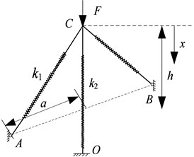
a)
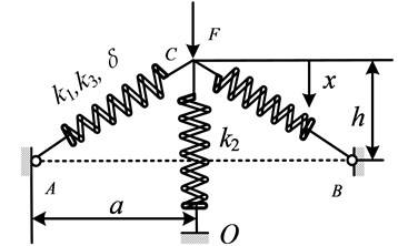
b)
The general equation between the force and the displacement can be derived as:
Introducing , , Eq. (1) can been recast in dimensionless form as:
where:
The dimensionless dynamic stiffness can be obtained by differentiating Eq. (2) to :
Using the Maclaurin series expansion, an approximate expression for the stiffness is found to be:
It is clear that the oblique springs can reduce the positive stiffness so that the linear natural frequency is smaller in the isolation range; and they introduce the cubic stiffness so that the peak response bends to higher frequencies, which potentially reduces the frequency region.
For a SDOF system depicted in Fig. 2. It includes a rigid mass suspended on a three springs mount in parallel with a viscous damper . denotes the vertical displacement from the equilibrium position caused by a harmonic excitation . The mass moves in the vertical direction through the guide rod and bushing. By applying the Newton’s second law, the motion equation of SDOF system can be expressed as
where:
Fig. 2Structural model of the SDOF system with HSLDS characteristic: 1 – loading platform, 2 – oblique spring, 3 – guide device, 4 – pillar, 5 – vertical spring, 6 – base plate, 7 – linear bearing, 8 – sliding rod
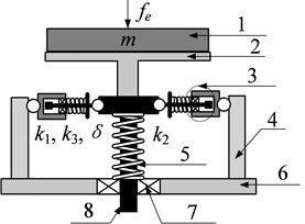
a)
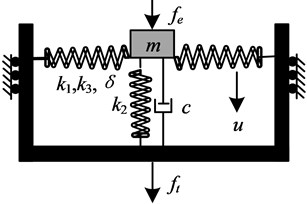
b)
3. Modeling of the HSLDS-VIS with elastic base
On the condition that taking the first order mode of the elastic base, it can be reduced to a rigid mass supported by a spring and damper. Therefore, the HSLDS-VIS with elastic base can be simplified to two-DOF mass-spring system, which is shown in Fig. 3. and denote the isolation equipment and the intermediate mass, respectively. is supported by a linear damper and a nonlinear spring which possesses both linear and cubic stiffness. is connected with a fixed plane using a linear spring and a linear damper. When the origins of coordinates are set at the position where the springs are not compressed, as shown in Fig. 3(a), the equation of the HSLDS-VIS with elastic base can be given by:
where is the damping coefficient of HSLDS vibration isolator; and are the linear and cubic stiffness coefficients of HSLDS vibration isolator, respectively. is the damping coefficient of damper between the and fixed plane; is the stiffness coefficient of the linear stiffness between the and fixed plane. and are the amplitude and frequency of the harmonic excitation, respectively.
Fig. 3HSLDS-VIS with elastic base. a) Coordinates not at the equilibrium state, b) Coordinates at the equilibrium state
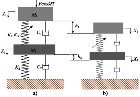
Note that the origins are not the equilibrium points of the system in Fig. 3(a), which is inconvenient for further analysis, and hence the coordinate transformation should be carried out. As is shown in Fig. 3(b), the origins of the new coordinates are set at the equilibrium state and the relations between the old and new coordinates are: , . In the equilibrium state, the gravitation terms in Eq. (6) can be eliminated by the following relations: and , where . The governing equations of Eq. (6) are given by:
Setting and introducing dimensionless parameters: , , , , , , , the first-order of the dimensionless motion equations are given by:
Therefore, the HSLDS-VIS with elastic base is a coupled nonautonomous dynamic system with quadratic and cubic nonlinearities.
4. Standard form of the motion equations
Standard form of the motion equations refers to the vector fields are proportional to the small perturbation parameter . Here, assume the nonlinear stiffness coefficients, damping coefficients and the amplitude of excitation force are small quantities and introduce an additional parameter into the equations. Setting , , , , Eq. (8) can be rewritten in the general form:
where:
The derivative equation of Eq. (9) is:
No damping and nonlinear force in the matrix , suppose it has only simple purely imaginary eigenvalues . The special solution of the homogeneous part with are as follows:
where and are real constants.
Setting , , , , where , substitute them into Eq. (11):
Substituting into Eq. (12), one may obtain:
where are the natural frequencies of the derived system. Substituting into Eq. (13) and separating the result into real and imaginary parts, yield the special solution of Eq. (10):
The same procedure may be easily adapted to obtain the special solution of the conjugate equation of Eq. (10), that is :
Introducing the coordinate transformation:
where , and are the general solution and special solution of Eq. (9), respectively. If and , yield:
Substitute Eq. (16) into Eq. (9) and one may obtain:
Based on the orthogonality [13] between Eq. (14) and Eq. (15):
If , , else if , . Multiplying Eq. (17) by and , respectively, and then summing from 1 to 4, the standard form of Eq. (9) was obtained as follows:
where , and are periodic functions of and with period .
5. Single-variable bifurcation equation based on the averaging method
Applying the singularity theory, we can reveal all possible bifurcation behaviors when the original system is subjected to a small perturbation. While the singularity theory is only suitable for autonomous system, it is essential to obtain the single-variable bifurcation equation by using the averaging method. For the system with multiple DOFs, perhaps there exists internal resonance. Introducing the first-order KB transformation:
where , , is detuning parameters, and are nonzero integers. and are periodic function of and . This paper focuses the second order primary resonance and 1:2 internal resonance, which means , and should meet and . The derivatives of the new parameters should satisfy the conditions below:
where and do not contain , and are periodic function of and . Applying the averaging method, substitute Eq. (20) and Eq. (21) into Eq. (19) and collect terms of the first order in :
where , , , , , are generalized Fourier series coefficients of and , . and are the slowly changing functions, while and are the fast changing functions. The following average equations are obtained:
where Letting , be zero, one may obtain:
Supposing and , the Eq. (24) is further recast as follows:
The governing equations of Eq. (25) are given by:
Substituting into Eq. (26) results in:
The same procedure may be easily adapted to obtain the following equations:
Substituting Eq. (27) into Eq. (28), the steady-state solution of Eq. (23) is obtained:
where the detailed are shown in Appendix A1. Setting , Eq. (29) can be written as follows:
where ~ is the universal unfolding parameters related to the stiffness coefficients, damping coefficients, tune parameters and so on, is the bifurcation parameter related to the amplitude of excitation force. The detailed ~ and are shown in Appendix A2.
6. Bifurcation analysis in the unfolding parameter space
In the singularity theory [14], the bifurcation Eq. (30) is the universal unfolding of the normal form , and the codimension is 4. The functions , and can be given by differentiating:
According to the definition of the transition set [15], it consists of bifurcation point set (BS), hysteresis point set (HS), and double limit point set (DLS).
at the point of . It is evident that .
at the point of . Setting and , was obtained. Setting and , was obtained.
at the point of . Because is a limit point, can be obtained. As for , will be discussed in the two-dimensions transition set.
However, from the fact that the bifurcation of Eq. (31) is the universal unfolding with 4-codimension, it is very different to analyze the bifurcation behavior in full detail. Therefore, it is necessary to discuss all forms of two parameter unfolding contained in Eq. (31), that is , , , , and . In this paper, only the transition sets and bifurcation diagrams in the plane and plane is presented.
Fig. 4Bifurcation diagrams of transition sets and persistent regions in the α1-α2 plane
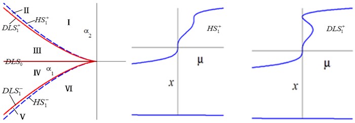

a) Transition set and its bifurcation diagrams in the plane


b) Bifurcation diagrams on different persistent regions in the plane
Setting one may obtain , , . The transition set in the plane is , as shown in Fig. 4. The whole parametric plane was divided into six different persistent regions by the transition sets, corresponding to different type of the solutions. When and change anticlockwise, the bifurcation diagrams are completely symmetric about axis between I--II--III and VI--V--IV.
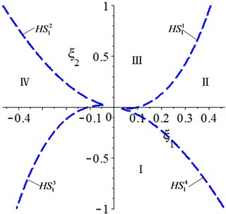
Setting , one may obtain , and . The transition set in the plane is , as shown in Fig. 5. The whole parametric plane was divided into four different persistent regions by the transition sets, corresponding to different type of the solutions. When and change anticlockwise, the bifurcation diagrams are completely symmetric about axis between I--II and IV--III.
Fig. 5Bifurcation diagrams of transition sets and persistent regions in the α3-α4 plane

a) Transition set and its bifurcation diagrams in the plane

b) Bifurcation diagrams on different persistent regions in the plane
Figs. 4-5 show that the bifurcation of HSLDS-VIS with elastic base with 1:2 internal resonance are considerable complex. There are qualitative difference of bifurcation diagrams between the different transition sets and persistent regions. If the unfolding parameters lying in the transition sets, a small perturbation is likely to cause a qualitative change in the bifurcation diagrams, which means that are degraded. While the unfolding parameters lying in the persistent regions, any perturbation is unable to cause a qualitative change in the bifurcation diagrams, which means that are universal.
7. Bifurcation analysis in the physical parameter space
Considering the HSLDS-VIS with elastic base under actual engineering background, the unfolding parameters and bifurcation parameters may be constrained by some conditions, which are called boundary induced transition sets. For example, the force amplitude, damping ratio and stiffness coefficient should be non-negative. Therefore, in order to obtain some results for the engineering application, it is essential that the bifurcation analysis is transferred from the unfolding parameter space to the physical parameter space. In this paper, only the transition sets and bifurcation diagrams in the plane are presented, whose physical parameter space consists of , , and . Setting , one may obtain:
Substitute Eq. (32) into and in Appendix A2:
Substituting Eq. (33) into , and are obtained in the physical parameter space as follows:
Setting and , yield , , , , , , . Substituting them into Eq. (34), the transition sets in the damping space are obtained, as shown in Fig. 6.
Fig. 6Transition set in the damping space
The analysis should be carried out with considering and in the actual engineering. Therefore, only the , II, and III are presented. Then, the bifurcation diagrams will also be transferred from the unfolding parameter space to the physical parameter space, whose procedure consists of two steps: first, the bifurcation analysis is transferred from the plane to the plane, and then, the bifurcation analysis is transferred from the plane to the plane. A point lying in is used as an example to illustrate the above process. Setting and substituting it into Eq. (31), yield , , and –9.234×10⁻⁹+5.093×10⁻⁹ and then, the bifurcation diagrams in the plane are obtained. Considering and according to , the bifurcation diagrams in the plane are obtained. The bifurcation diagrams in the physical parameter space are shown in Fig. 7. When lying in , all of the bifurcation diagrams have a hysteresis point. When lying in and region III, the multiple solutions cannot coexist on the system; while lying in region II, the same corresponds to two or three amplitudes in some areas. The system has three different bifurcation behaviors in the physical parameter space, therefore, the beneficial movement mode can be selected by adjusting the parameters, which offers a theoretical guidance for design and application of the HSLD-VIS with elastic base.
Fig. 7Bifurcation diagrams in the physical parameter space
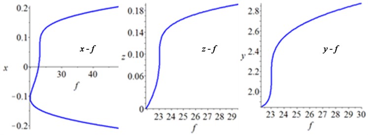
a) lying in

b) lying in region III

c) lying in region II
8. Conclusions
In this work, the restoring force of the HSLDS-VIS was approximated to linear and cubic stiffness and the motion equations of HSLDS-VIS with elastic base were established. The averaging method was applied to obtain the single-variable bifurcation equation for the HSLDS-VIS with elastic base in case of primary resonance and 1:2 internal resonance. According to singularity theory, the transition sets and bifurcation diagrams in the unfolding parameter space were studied. For the engineering application, the transition sets were transferred back to the physical parameter space, thus to obtain the bifurcation behaviors of the amplitude with respect to the external force. Analytical results show that local bifurcations of HSLDS-VIS with elastic base in case of 1:2 internal resonance are considerable complex and should be analyzed in engineering with considering the constrained conditions of the physical parameters. Additionally, the excitation force may change the values of unfolding parameters and the types of the bifurcations, which can provide a theoretical guidance for design and application of the HSLDS-VIS with elastic base.
References
-
Shaw A. D., Neild S. A., Friswell M. I. Relieving the effect of static load errors in nonlinear vibration isolation mounts through stiffness asymmetries. Journal of Sound and Vibration, Vol. 339, 2015, p. 84-98.
-
Lan Chao Chieh, Yang Sheng An, Wu Yi Syuan Design and experiment of a compact quasi-zero-stiffness isolator capable of a wide range of loads. Journal of Sound and Vibration, Vol. 333, 2014, p. 4943-4858.
-
Carrella A., Brennan M. J., Waters T. P. On the design of a high-static-high-dynamic stiffness isolator using linear mechanical springs and magnets. Journal of Sound and Vibration, Vol. 315, 2008, p. 712-720.
-
Wu Wenjiang, Chen Xuedong, Shan Yuhu Analysis and experiment of a vibration isolator using a novel magnetic spring with negative stiffness. International Journal of Mechanical Sciences, Vol. 81, 2014, p. 207-214.
-
Zhou Jia Xi, Wang Xin Long, Xu Dao Lin, et al. Experiment study on vibration isolation characteristics of the quasi-zero-stiffness isolator with cam-roller mechanism. Journal of Vibration Engineering, Vol. 28, Issue 3, 2015, p. 449-455.
-
Li Qiang, Zhu Yu, Xu Dengfeng, et al. A negative stiffness vibration isolator using magnetic spring combined with rubber membrance. Journal of Mechanical Science and Technology, Vol. 27, Issue 3, 2013, p. 813-824.
-
Meng Lingshuai, Sun Jinggong, Wu Wenjuan Theoretical design and characteristics analysis of a quasi-zero stiffness isolator using a disk spring as negative stiffness element. Shock and Vibration, 2015, p. 813763.
-
Liu Xingtian, Huang Xiuchang, Hua Hongxing On the characteristics of a quasi-zero stiffness isolator using Euler buckled beam as negative stiffness corrector. Journal of Sound and Vibration, Vol. 332, 2013, p. 3359-3376.
-
Zhou N., Liu K. A tunable high-static-low-dynamic stiffness vibration isolator. Journal of Sound and Vibration, Vol. 329, 2010, p. 1254-1273.
-
Yoshikazu Araki, Kosuke Kimura, Takehiko Asai, et al. Integrated Mechanical and material design of qua-zero-stiffness vibration isolator with superelastic Cu-Al-Mn shape memory alloy bars. Journal of Sound and Vibration, Vol. 358, 2015, p. 74-83.
-
Niu Fu, Meng Lingshuai, Juan Wen, et al. Design and analysis of a quasi-zero-stiffness isolator using a slotted conical disk spring as negative stiffness structure. Journal of Vibroengineering, Vol. 16, Issue 4, 2014, p. 1875-1891.
-
Hassan Ameer On the local stability analysis of the approximate harmonic balance solutions. Nonlinear Dynamics, Vol. 4, 1996, p. 105-133.
-
Carrella A., Brennan M. J., Waters T. P., et al. Force and displacement transmissibility of a nonlinear isolator with high-static-low-dynamic-stiffness. International Journal of Mechanical Sciences, Vol. 55, 2012, p. 22-29.
-
Lu Zeqi, Brennan Michael J., Yang Tiejun, et al. An investigation of a two-stage nonlinear vibration isolation system. Journal of Sound and Vibration, Vol. 332, 2013, p. 1456-1464.
-
Gatti Gianluca, Kovacic Ivana, Brennan Michael J. On the response of a harmonically excited two degree-of-freedom system consisting of a linear and a nonlinear quasi-zero stiffness oscillator. Journal of Sound and Vibration, Vol. 329, 2010, p. 1823-1835.
-
Guo P. F., Lang Z. Q., Peng Z. K. Analysis and design of the force and displacement transmissibility of nonlinear viscous damper based vibration isolation systems. Nonlinear Dynamics, Vol. 67, 2012, p. 2671-2687.
-
Yang J., Xiong Y. P., Xing J. T. Dynamic and power flow behavior of a nonlinear vibration isolation system with a negative stiffness mechanism. Journal of Sound and Vibration, Vol. 332, 2013, p. 167-183.
Cited by
About this article
The research leading to these results has received funding from the National Natural Science foundation of China (NSFC) under grant No. 51579242, No. 51509253 and No. 51679245. All the supports mentioned above are gratefully acknowledged.
