Abstract
Structure-Air noise sources in different frequencies were identified based on analysis of frequency and testing of vibration and noise under idling condition, and a method for signal sources priority was developed under identifying the kinds of noise sources. The partial coherence equations of the six input and single output systems were derived based on the theory of coherence. Coefficient of partial coherence of the test data of vibration and noise in vehicle was calculated by using MATLAB. Coherence analysis results show that working engine incentive transferred to the driving cab in low frequency range caused structure noise, engine RH mounting is the main noise source; The noise in middle frequency range is caused by the coupling effects of vibration of engine left mounting and noise of the engine compartment to the driving cab, between which left hanging mount vibration affected more; Engine compartment noise in high frequency leaked through the air to the cab, engine noise is the main source of noise inside.
Highlights
- A signal source sorting method based on the recognition of noise source type is proposed.
- Based on coherence theory, a six-input single-output linear system is established, and the calculation formula of partial coherence is deduced.
- The partial coherence coefficients of vibration and noise measurement points and interior noise are calculated by using MATLAB programming.
- Identify the main noise sources at different frequencies by partial coherence analysis based on priority ranking of structural-air noise sources.
1. Introduction
With development of the international economic, cars ownership increased level year by year. Consumers demanding increasingly for the quality of the vehicle, there are studies showed that vehicle fault complaints about NVH (Noise, Vibration, Harshness) control are almost 1/3 of the problems [1]. As an important indicator of the driving comfort of passenger, the size of the noise in the car is not only the key to improve vehicle quality, but also the embodiment of the core competitiveness of enterprises. Therefore, it is imperative to control the noise level inside the vehicle effectively.
In order to control the noise inside the car effectively, the theories and methods proposed by the researchers for noise source identification can be summarized as the traditional noise source identification method, the analysis methods based on signal processing technology and the sound source recognition method based on visualization technology [2, 3]. The traditional noise source identification method and the visualization-based sound source recognition method are widely used in the simple sound source and surface noise recognition [4]. When they are applied to the automobile which exist plurality of noise sources, multiple vibration components and acoustic coupling complex system, the identification of low precision and high cost of the experiment are highlighted. The method based on digital signal processing has obvious advantages in recognition accuracy, test method and by contrast.
Coherence analysis to identify the vehicle noise source belongs to a method of the digital signal processing, the coherence function dates from the correlation theory. Correlation function is applied in time domain for the testing signal acquisition, coherence function is applied in the frequency domain [5]. There are three kinds of coherence functions, of which the partial coherence function is based on the usual coherence theory [6], which can be regarded as a special coherent function. The partial coherence analysis is used to calculate the linear coefficient of influence of the independent input on the output in the frequency domain [7], which is different from the application of constant coherence analysis on identification of noise sources. In the premise of correcting the priority of the vibration, noise sources, the partial coherence analysis can eliminate the influence of other related inputs [8], which is promising in the practical application of vehicle noise sources identification.
This paper identifies the Structure-Air noise sources based on the analysis of the vibration and noise of the vehicle, classifies the signal source priorities based on the noise source category judgment, and uses the coherence analysis method to accurately identify the noise source that triggers the noise in the vehicle
2. Coherence analysis theory
2.1. Multiple input single output system model
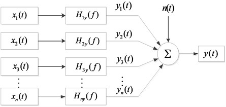
The practical problem of engineering must be based on the correct theoretical model. The multi-input single-output system model of the noise sources in the coherence analysis is shown in Fig. 1, where represents input signal, represents transfer function from input to output; is the output of the ideal linear system with constant parameters, is the sum of all deviations and ideal output records [9].
Fig. 1Independent and unrelated multi-input single output system
Coherence function is delimited as Eq. (1) in ideal linear system with constant parameters [9]:
where represents the coefficient of usual coherence, represents cross-spectral density functions, and are the auto-spectral density functions of and respectively.
2.2. Partial coherence calculation
Partial coherence functions were developed under usual coherence functions, difference between which is that power spectrum records of partial coherence functions are conditioned, the conditioned records can remove other coherence input records and calculate residual records effects to output records, there are hypothesis according to Fig. 1:
(1) All the signal records are smooth, the input signals can be coherent or irrelevant.
(2) The coherent function between any two input records are not 1, and the partial coherence function between the output signal and any of the input signals is not 1.
Calculation of partial coherence function and its conditional power spectrum with two input / single output system will be proved as an example:
, denote the input signal and output signal of the recording length have removed the effect of . The system models are shown in Fig. 2.
Fig. 2Two input/single output model
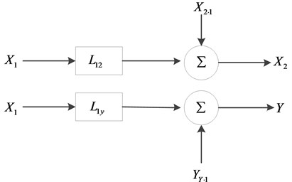
and in Fig. 2 are transfer functions of to and respectively, equations are as follow:
On top of which, , and are auto-spectral density and cross-spectral density functions of and , the model removed shown in Fig. 3, where is the transfer function of and, donates noises removed effect of and .
Fig. 3System model removed the effect of x1(t)

Conditioned records without defined by:
where “*” donates complex conjugate, is the record length of the finite Fourier transform, and are conditional autospectral density functions of and which removed effect of respectively. is conditional cross-spectral density function without effect of . In Fig. 3 defined by:
Conditional power spectrum can be obtained as follow when Eqs. (2)-(5) are brought into Eqs. (6), (7) and (8):
Partial coherence functions of and defined by:
where is the coefficient of partial coherence of and , there are inequality: 1, if and are irrelevant, then:
From the above, it can be seen that the conditional power spectrum and the partial coherence function have the characteristic of eliminating the coherence between the signals and do not change the coherence between the outputs.
For the cases, where signals can be measured, with arbitrary signals and one output , in order to descript conveniently, the order of recording is as follow:
Every conditioned autospectral density and , cross-spectral density functions can be calculated as follows:
where the optimal system is calculated as follow:
If is substituted as , then becomes , where:
For any , where 1. For any , 0, if replaced by , then the equation is as follow:
Partial coherence function can be obtained when Eqs. (8), (9) and (10) are brought into Eq. (22), then:
The actual vehicle operating system vibration and noise transmission is coupled, non-independent [10]. The covariance calculation introduces the concept of residual spectrum [11], which solves the problem of non-independent input of multiple input signals in the actual engineering situation. It can calculate the contribution of each input to the output after eliminating the coherent influence among the input signals, based on which, the establishment of a multi-input single-output system among the input signals is equivalent to meet the independence. The model theory application conditions: Assume that the noise source signals are stationary random signals, the system is a constant parameter linear system. The system model of the multi-input single-output partial coherence calculation is shown in Fig. 4.
Fig. 4Multi-input single output system
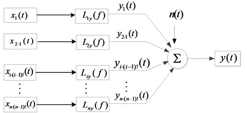
Fig. 4 is a set of ordered conditional input records instead of the original known input records, the condition input selected in the order shown in Fig. 4 is recorded as 1, 2, …, . For any , signal represents the under the pre-signals of , , conditions. These ordered conditional inputs are uncorrelated, and the partial coherent system model solves the limitation of the input signal correlation in the coherence theory application. This kind of ordered input has the usual coherence function method, Bae et al. [12] and Park et al. [13] developed the impulse response function method and the Hilbert transform method. In the literature [14], the above method is proved for disadvantages. In this paper, the input record sorting method based on Structure-Air noise source identification is proposed. On the basis of judging the noise source type, the priority of the structure noise source is higher if the structure noise in a band or operating condition is dominant. As the same, the air noise sources have the higher priority if the air noise is dominant.
3. Application of coherence analysis on identification of vehicle noise sources
3.1. Analysis on the mechanism and transmission of vehicle interior noise
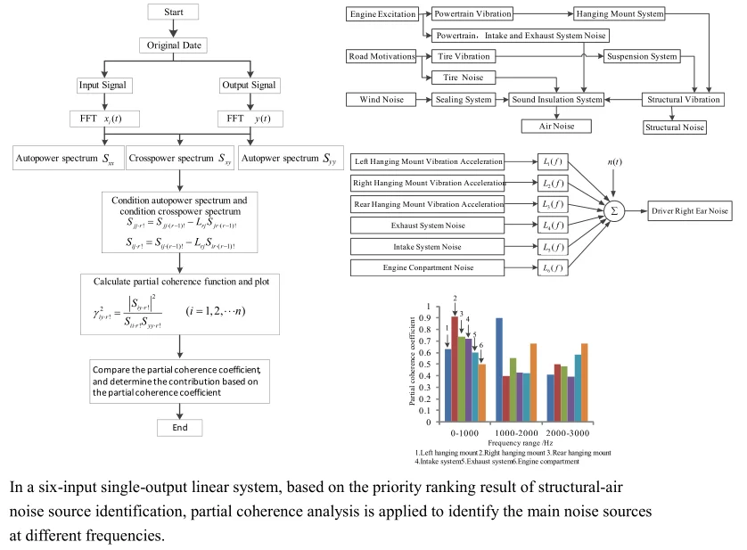
Rank the priority of the signal source firstly before analyzing the noise generation mechanism and distinguish the noise source category. Passenger car noise in accordance with the transmission path can be divided into structural noise and air noise, of which noise generation mechanism and transmission as shown in Fig. 5.
Fig. 5The mechanism and transmission of vehicle interior noise
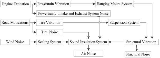
The structural noise is mainly driven by the engine, the road motive power assembly and its accessories, the suspension system to the car caused by the body plate vibration generated. The air noise is mainly caused by the surface noise of the engine, the noise of the intake/exhaust system, the cooling fan, the noise of the tire and other system noise through the vehicle body pore leakage. This paper mainly studies the causes of noise in the vehicle under the fixed conditions, so the vibration and noise generated by the engine excitation and its accessories are mainly considered. This paper mainly studies the correlation analysis of noise and related vibration in the vehicle at idle speed (800 r/min), so the vibration and noise generated by the engine excitation and its accessories are mainly considered.
3.2. Experiment of vehicle interior noise test
Design the testing for a sport utility vehicle to identify noise sources in vehicle interior based on GB/T18697-2002 “Acoustic Vehicle Noise Measurement Method”. The vibration and noise generated by the engine excitation and its accessory system are the main factors. The vibration acceleration of engine RH mounting, the intake and exhaust system and the engine compartment noise are used as the input signals in the system model at idle speed of 800 r/min. The sound pressure signal at the right ear of the driver responds to the noise level in the vehicle, and the in-vehicle noise sound pressure signal collected by the ICP microphone is used as the output , the exterior noise measurement point is used as the auxiliary analysis testing point of the Structure-Air noise.
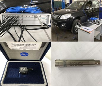
The test devices of vibration and noise test for noise source identification is shown in Fig. 6. The main components are Test Vehicle, LMS SCADAS Mobile, American PCB Three-Way Vibration Sensors, Denmark GRAS Microphones. The data acquisition device can collect dynamic real-time test data, whose speed can reach 17 M 24 bit sampling points per second. The maximum sampling rate channel is 204.8 KHz, the whole dynamic range are up to 170 dB. The sampling frequency is 6400 Hz, the frequency resolution is 1 Hz in the test.
Fig. 6The experiment devices
The specific layout of vibration and noise sensors are shown in Fig. 7. The sound pressure of the driver’s right ear can reflect the noise level in the cab. The sound pressure microphone outside the car is used to compare noise outside and inside the vehicle to assist in judging the noise characteristics inside. In order to achieve the vibration isolation effect, all the sound pressure sensors and the fixed point of installation have soft soundproof cotton. The vibration sensors and the mounting point link with paraffin, which can be regarded as rigid connection.
Fig. 7Vibration and noise measurement points layout
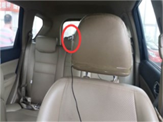
a) Right ear noise measurement point
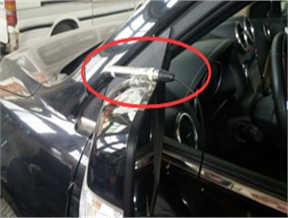
b) Outside noise measurement points
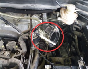
c) Air intake noise measurement points
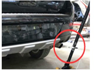
d) Exhaust noise measurement points
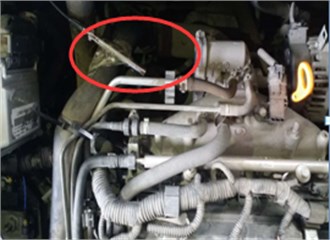
e) Engine compartment noise measurement point
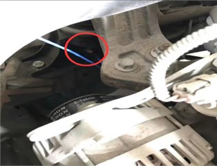
f) Passive side left hanging point of engine
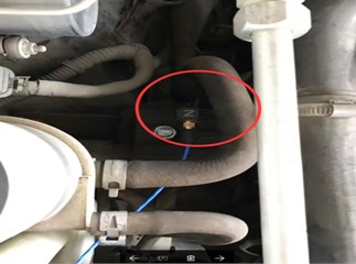
g) Passive side right hanging point of engine
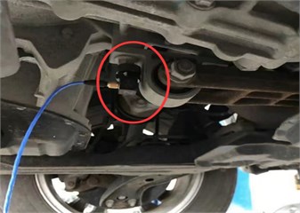
h) Passive side rear hanging point of engine
3.3. Analysis of vibration characteristics in vehicle interior
3.3.1. Analysis of structural-air noise characteristics
Spectral analysis of vibration and noise measurements can directly react to test results without disrupting the noise source associated with the receiver [15]. Analysis comparison of the noise measurement point of the 1/3 octave curve (A-weight) in Fig. 8. The vibration autopower spectrum of three passive side hanging mount points of engine in Fig. 9 and the noise autopower spectrum of each system in Fig. 10 are used as auxiliary analysis. The main peak frequencies of vibration and noise in Fig. 9 and Fig. 10 are shown in Table 1.
Table 1Noise energy concentration frequency in main operating system
Noise sources | Unit: Frequency / Hz | |||||||
Hanging mount of engine | Left | 13 | 27 | 1017 | – | – | – | – |
Right | 13 | 27 | 945 | 1143 | – | – | – | |
Rear | 13 | 27 | 50 | 571 | – | – | – | |
Intake system | 570 | 1024 | 1143 | 1235 | 1370 | 1715 | 2275 | |
Exhaust system | 27 | 53 | 106 | 133 | 160 | 1157 | 1245 | |
Engine room | 571 | 1144 | 1157 | 1209 | 1229 | 1240 | 1273 | |
Fig. 8Octave 1/3 between inside and outside of vehicle autopower spectrum
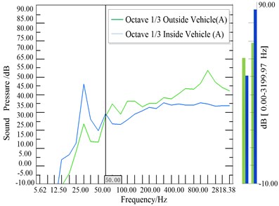
Fig. 9Passive side suspension point acceleration
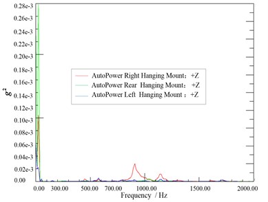
Fig. 10Exhaust, intake, engine room noise autopower spectrum
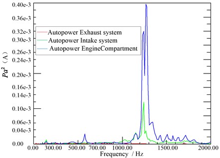
It can be seen from Fig. 8 that noise value is significantly higher than the outside the car below 50 Hz, the noise in the car is obvious in the low frequency band, the peak value is especially prominent at 25 HZ, it is nearly 45 dB. In the frequency band above 400 Hz outside noise sound pressure value increased rapidly, where the sound pressure value near 400 Hz is about 35 dB, of which, the maximum of value is almost 55 dB. Fig. 8 identifies the identification of noise sources in the low frequency range below 50 Hz and 400 Hz in the above high frequency band. From the autopower spectrum of the vibration acceleration measuring point in Fig. 9, it can be found that the vibration measurement point of the engine hanging mounts have obvious peaks below 1400 Hz and the energy in the low frequency band below 300 Hz is the strongest. In Fig. 10, there are obvious peaks over 500 Hz for the air system noise, of which over 1000 Hz high-frequency energy is the strongest.
Further analysis of the main peak frequency causes, combined with the noise generation mechanism, it can be seen that the noises are from the system excitation, the engine is the main source of excitation under idling conditions. Different speed, order and frequency of the combination of sound will have different effects. The relationship between the vibration, noise of the engine and the intake/exhaust system and speed, order and frequency is expressed by the following equation:
From above, the fundamental frequency of the engine is 13.33 under idling condition of 800 r/min, and the main peak frequency of the noise source is found in the vicinity of the fundamental frequency and resonant frequency of the engine compared with the date of Table 1, the second order excitation has the largest proportion.
The reason for the initial noise in the vehicle under idling is as follows: In the effective analysis of the frequency, the low frequency is mainly caused by the vibration of the engine being transmitted to the vehicle body via the hanging mounts to cause driving room structure vibration, structure noise at low frequency are the main. Noise in the car at high frequency energy is more concentrated, it is probably caused by the intake/exhaust noise and engine compartment noise through the air through the body pores into the car, where air noise is the main.
3.3.2. Noise source identification of coherence analysis in vehicle interior
The results of the vehicle noise characteristics analysis and the identification of the air noise source solve the problem of prioritization of signals in partial coherence analysis.
The rubber mounting of the engine is actually a nonlinear system, but the test condition is a fixed speed condition, which can be regarded as a weak linear system. The collected data is normal and stable under the random process. According to the coherence theory, it is suitable for analysis [9]. The process of partial coherence analysis is shown in Fig. 11.
Using the six noise source measurement points of the Structural-Air noise source identification test as input signals, the driver's right ear sound pressure signal as an output, built a six-input single-output linear system shown in Fig. 12. When the noise source is identified at the low frequency, the signal of the engine vibration is placed in the first place. When the air noise source is identified, the peak energy of the spectrum higher is placed as the same.
As the sampling frequency in the test is 6400 Hz, it can be seen from the Shannon’s sampling theorem, , that the maximum frequency of the data collected in this test is 3200 Hz. In order to ensure the validity of signal analysis, the analysis frequency is determined in the range of 0-3000 Hz, with 0-1000 Hz as the low frequency band, 1000-2000 Hz as the middle frequency band and 2000-3000 Hz as the high frequency band. According to the process of partial coherence analysis, the partial coherence function curves of the three passive side mounting points, the intake/exhaust system and the engine compartment are calculated at idle speed 800 r/min as shown in Fig. 13.
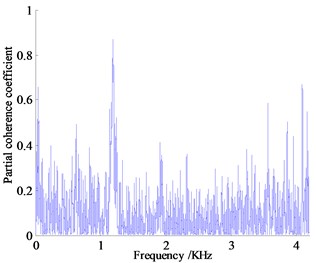
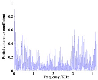
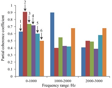
Analysis the partial coherence functions in Fig. 13 can know that the contribution of vibration and noise to the vehicle focus on the low frequency range, the vibration and noise measurement points below 1000 Hz contribute a lot for the noise in the vehicle, where the partial coherence coefficient of right hanging mount at 41.14 Hz is almost 0.91, left and rear hanging mount in the same range reach 0.63 and 0.74 respectively, the partial coherence coefficient of exhaust system at 13.71 Hz reach 0.68. The noise of engine compartment near 931 Hz reaches about 0.50, contribution of vibration measurement points are high obviously, which indicates that the vehicle interior noise in vehicle is caused by the engine vibration under idling condition with low rotating speed transfer to the body and frame of a vehicle causing the car wall structure noise, the engine vibration is the main noise source, where vibration transfer from right hanging mount contributes more.
Fig. 11Partial coherence calculation block diagram
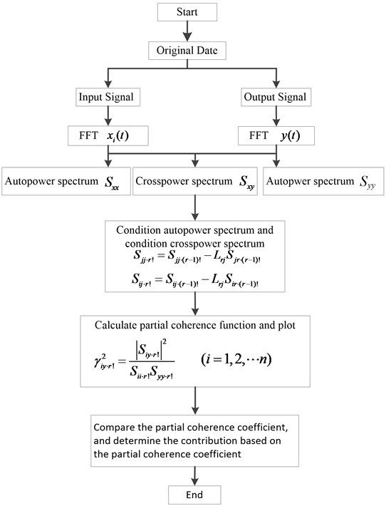
Fig. 12Six-input single-output system

Fig. 13Partial coherent curve of vibration and noise measurement
a) Partial coherent curve of left hanging mount
b) Partial coherent curve of right hanging mount
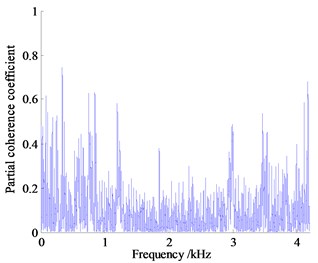
c) Partial coherent curve of rear hanging mount
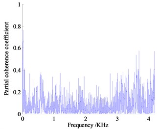
d) Partial coherent curve of intake system
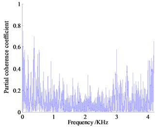
e) Partial coherent curve of exhaust system
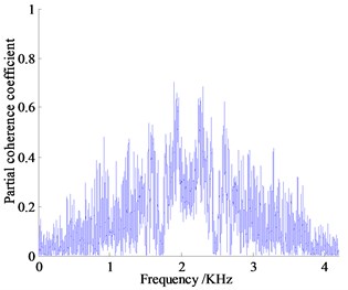
f) Partial coherent curve of engine compartment
In 1000 Hz-2000 Hz frequency band, the peak of partial coherence of vibration measuring point is concentrated near 1250 Hz, among which the left-handed partial correlation coefficient is the largest, about 0.90, the second is the rear hanging mount followed by the partial correlation coefficient about 0.60. The engine compartment of air noise near the frequency has the largest partial coherence coefficient about 0.65, which is the main source of air noise. Judging from the size of the partial coherent contribution coefficient, the reason why the noise in the frequency band reaches relatively high is that the coupling of air noise and structure vibration noise transmitted to the cab result in the increase of the noise pressure value inside the car.
In the range of 2000-3000 Hz, the partial contribution of the vibration measurement points decrease overall, and the maximum partial correlation coefficient of the right and the rear hanging mount both reach almost 0.50. The contribution of air noise to the interior noise is enhanced. The coherence coefficient of the engine compartment is the largest, about 0.75, and the noise of the exhaust system is the second, about 0.60, which indicates that the combustion noise of the engine and the noise of the exhaust system leak through the air to the cab, of which engine compartment noise is the main source of noise.
The results of the different frequency bands of the coherent identification of the vehicle noise source are plotted in Fig. 14, and the results of the above analysis showed that the vibration and noise are coupled in each frequency band under the idling condition; the main noise source caused by the noise in the idle condition is the engine system. The vibration of the right hanging mount of engine is the largest contribution to the structural noise generated by the engine. At the same time, proved the reason why the overall sound pressure level in vehicle interior of Fig. 8 is higher than that in outside of the vehicle.
The above analysis shows that the partial coherence analysis based on the order of the Structure - Air noise source identification priority can accurately identify the main noise source at different frequencies, and it is effective in solving the practical engineering problems.
Fig. 14Partial coherence of vibration and noise in different frequency bands: 1 – left hanging mount, 2 – right hanging mount, 3 – rear hanging mount, 4 – intake system, 5 – exhaust system, 6 – engine compartment
4. Conclusions
Through the real-time data acquisition and the test data processing of vibration and noise in vehicle based on the coherence analysis theory, the following conclusions can be drawn:
1) Based on the Structure-Air noise sources identification and the input signal priority ranking, the coherence analysis can be used to quantify the noise sources and determine the main noise sources which affect the noise inside the vehicle, also have good application value from the analysis method and the recognition effect.
2) For a sport utility vehicle, applying coherence theory to the vibration and noise data in a testing vehicle under idling condition to identify noise sources got the follows: 1) At low frequencies, the engine vibration is the main source of noise. The partial coherence coefficient is about 0.9 in the vicinity of 41 Hz, and the right hanging mount vibration of the engine is the main contribution source; 2) At middle range of frequencies, the rear hanging mount vibration of the engine and the exhaust system noise coupling affect, partial coherence coefficient of exhaust system reach 0.68 in the vicinity of 1893 Hz, exhaust noise is the main noise source; 3) The left hanging mount vibration of the engine at 1250 Hz is the main structural noise source between mid-frequency range, the contribution coefficient of partial coherence is 0.9, the noise of engine system is the main source of air noise, and the partial coherence coefficient is about 0.45.
3) According to the size of the coherence coefficient, the partial coherence coefficient of the low frequency band of 0-1000 Hz is obviously higher than that of other frequency bands, which is the main noise frequency band under the idling condition of the vehicle.
References
-
Liang X., Sen H. Present status and prospect on vehicle NVH technology. Automobile Parts, Vol. 8, Issue 5, 2013, p. 78-81.
-
Gaoshan F., Yuhong L., Tielin Sh Test and analysis of pass by noise source on a heavy-duty vehicle. Science Technology and Engineering, Vol. 12, Issues 34, 2012, p. 9439-9441, 9452.
-
Yixian H., Shunming L., Yuanyuan Zh, et al. Reviews of vehicle noise source identification methods. Noise and Vibration Control, Vol. 32, Issue 5, 2012, p. 11-16.
-
Jianqiang X., Juhua H., Qun L. Review of theories and methods of noise source identification of vehicle. Noise and Vibration Control, Vol. 31, Issue 4, 2011, p. 97-101.
-
Quan W., Weikang J. Partial coherence method of cyclostationary signal. Journal of Mechanical Engineering, Vol. 41, Issue 7, 2005, p. 174-179.
-
Shibo X., Changyi H. Fundamentals of Mechanical Measurement Technology. China Machine Press, Bei Jing, 2006, p. 172-182.
-
Rongbin Zh, Changxing H., Yongbin Zh Identification of excavator cab’s noise based on partial coherence analysis. Noise and Vibration Control, Vol. 31, Issue 4, 2011, p. 106-110.
-
Tianfei M., Chun R., Dengfeng W., et al. Experimental research of interior noise reduction for passenger car. Automobile Technology, Vol. 42, Issue 5, 2011, p. 11-13.
-
Hailan Zh, Hongzhen W. Calculation of identifying noise source based on partial coherence analysis. Noise and Vibration, Vol. 25, Issue 5, 2005, p. 31-33.
-
Xudong W., Shuguang Z., Lei L. Simulation of suspension-tire system model based on rear axle of twist beam. Applied Mechanics and Materials, Vol. 34, Issue 35, 2010, p. 1906-1910.
-
Chengtai H., Yunkai G. Noise identify and control in excavator based on frequency spectral analysis and coherence analysis. Journal of Vibration Measurement and Diagnosis, Vol. 32, Issue 6, 2013, p. 1035-1036.
-
Bae B. K., Kim K. J. A Hilbert transform approach in source identification via multiple input single-output modeling for correlated inputs. Mechanical Systems and Signal Processing, Vol. 12, Issue 4, 1998, p. 501-513.
-
Park J. S., Kim K. J. Determination of priority among correlated inputs in source identification problems. Mechanical Systems and Signal Processing, Vol. 6, Issue 6, 1992, p. 491-502.
-
Moli Ch, Shunming L. Coherence functions method for signal source identification. China Mechanical Engineering, Vol. 18, Issue 1, 2007, p. 95-100.
-
Yanyan Z., Mingliang T., Mingming N. Review of automobile noise regulations and pass-by noise simulation methods. Science Technology and Engineering, Vol. 14, Issue 21, 2014, p. 127-179.
Cited by
About this article
This research was supported under Scientific Research Fund of Department of Education of Liaoning Province of China (LG201618).
