Abstract
In order to compare the performance of heavy truck suspension system, a 3D dynamic model with 14 degrees of freedom is developed with the dynamic models of the traditional and new air suspension systems to compare the performance of the air suspension systems for reducing the negative impacts on the road surface when vehicle moves on the different road conditions. Dynamic modes of two different types of the air suspension systems are respectively established and a dynamic load coefficient (DLC) is chosen as objective function which uses Matlab/Simulink software to simulate and determine the values of objective function. The results shown that the performance of the new air suspension system is better than the tradition air suspension for reducing the negative impact on road surface under the different operating conditions of vehicle. Especially, the DLC values of wheels at 3rd axle of vehicle with the new air suspension system are respectively reduced by 6.7 %, 7.0 %, 7.4 %, 7.7 % and 8.5 % in comparison with the traditional air suspension system when vehicle moves on the different pavement conditions a velocity of 20 m/s and fully loaded. In addition, the study results not only can provide a reference for designers but also traffic management to reduce the negative impact on road surface.
1. Introduction
Vehicle suspension system plays an important role not only in improving the ride comfort movement but also reducing the negative impacts of road surfaces. A three-dimensional 3D vehicle-pavement coupled model to simulate the pavement dynamic loads induced by the vehicle-pavement interaction where both the vehicle vibration and pavement deformation were introduced by X. M. Shi and C. S. Cai [1]. The study results indicated that under rough road conditions the dynamic loads of vehicles are significantly higher than the static loads. Based on the analysis of nonlinear geometric characteristics of the suspension systems and tires, a 3D nonlinear dynamic model of a typical heavy truck is developed by Le Van Quynh, etc. [2]. The impact factors of dynamic tire loads are used to evaluate the dynamic interaction between heavy vehicles. The study results provide both the warning limits of road surface roughness and the limits of corresponding dynamic parameters for the 5- axle heavy truck.
Air suspension is increasingly used on heavy vehicles due to its capabilities of providing better ride quality and reducing the negative impacts of road surfaces. A semi-active suspension system with a rolling lobe air spring is firstly modeled and a novel front axle vertical acceleration-based road prediction model is constructed by Zhengchao Xie, etc. [3]. Simulation results show that the ride quality, the road holding, the handling capability, the road friendliness, and the comprehensive performance of the semi-active air suspension with FPW outperform those with the traditional active suspension with PID-wheelbase preview controller (APP).
Nowadays, the dynamic model of the air suspension system is increasingly developed to improve vehicle performance and the basis for mathematical models of air springs is to measure its mechanical properties. The mechanical behavior of air springs is often very complicated. The behavior is mainly based on fluid dynamic and thermodynamic mechanisms, where important quantities in such mechanisms are pressure, volume, temperature, mass flow rate, density, and energy of the air as well as shape of the air volume [4]. There exist many different kinds of the air spring models, such as Nishimura, VAMPIRE, SIPPAC, and GENSYS. However, only the GENSYS model [4, 5] is fully descriptive the three different effects of the air spring as the elastic stiffness, the friction damper and the nonlinear viscous damper.
The major goal of this study is to develop the dynamic model of a semi-trailer truck using two different types of the air suspension system at the second axle and the third axle for comparing and analyzing the influence of the performance of suspension system on the road surface. A dynamic load coefficient (DLC) is chosen as objective function which uses Matlab/Simulink software to simulate and determine the values of objective function. Both the traditional dynamic model and Gensys’s dynamic model of the air suspension systems are selected for comparing the performance of suspension systems when vehicle moves the different conditions, such as the different vehicle speeds and road surface roughness.
2. Vehicle dynamic model
2.1. Full vehicle dynamic model
A 5-axle semi-trailer truck with a dependent suspension system for the front axle and a walking beam suspension system for the rear axles are developed for comparing the performance of suspension system. A semi-trailer truck dynamic model with 14 degrees of freedom is established for comparing the performance of the traditional and new air suspension systems, as shown in Fig. 1(a), 1(b). Dynamic modes of two different types of the air suspension systems including a tradition dynamic model and new dynamic model for the second axle and the third axle of semi-trailer truck is respectively established, as shown in Fig. 1(c), 1(e) and the new air spring model is shown in Fig. 1(d).
Fig. 1Vehicle and air suspension system dynamic model
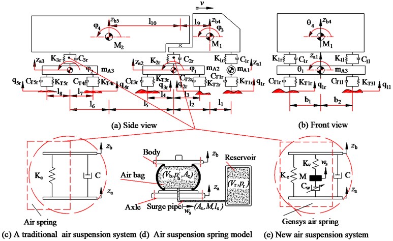
In Fig. 1, Kij are the suspension stiffness coefficients; Cij are the suspension damping coefficients; KTkj are the stiffness coefficients of tires; CTkj are the damping coefficients of tires; M1 and M2 are the sprung mass of the tractor and trailer, respectively; mAi are the unsprung mass of the front axles, respectively; ln and bm are the distances; zai and zbm are the vertical displacements at the centre gravity of the axles tractor and trailer; θk are the angle deflection at the centre gravity of the axles, tractor and trailer; φh are the angle deflection at the centre gravity of tractor and trailer; v is the speed of vehicle; Ke is the air spring stiffness coefficient; C is the passive damping coefficient; Cw is the nonlinear viscous damper of the air spring; Kv is the viscous stiffness constants; M is the mass of the surge pipe; Ae is the effective area of air bag, pb is the pressure in air bag; As is the cross section area of the pipeline, ws is the displacement of air in surge pipe; ls is the length of the surge pipe; Vb is the volume of air bag. Vr is the volume of reservoir (i=1, 2, 3; j=r, l; k=1, 2,..., 5; n=1, 2,..., 10; m=1, 2; h=1, 2, 3, 4).
In order to facilitate the description of vehicle vibration systems using computer simulation, a combined method of the multi-body system theory and D’Alembert’s principle is chosen in this study. The general dynamic differential equation for 3-axle semi-trailer truck is given by the following matrix form:
where M, C, K, CT and KT are the mass matrix of the vehicle, damping matrix of the suspension system, stiffness matrix of the suspension system, damping matrix of the wheel system and stiffness matrix of the wheel system, respectively; z is the vector of displacement; Q is the vector of excitation of road surface.
2.2. Air suspension system dynamic model
1) Traditional dynamic model. The air suspension dynamic model has been proposed by many researchers such as Nishimura, VAMPIRE, SIPPAC. In this study, the dynamic model of the traditional air suspension system is shown in Fig. 1(c). The vertical force of the air suspension is defined as:
where, the air spring stiffness coefficient Ke is determined based on the laws of thermodynamics method [3] and the air spring stiffness coefficient is developed a new method based on the variation of the volume, area, and other structural parameters of the air spring. Therefore, the interior air pressure of the air spring is also changed to calculate the air spring stiffness. The air spring stiffness can be obtained by the derivative of ratio elastic force and displacement of the air spring, as follows:
The effective volume and area are defined as:
Based on the laws of thermodynamics [6], if the compression or the expansion stroke of the air spring is rapid enough, it can be regarded as an adiabatic process. Thus, the air state of the air spring can be defined as:
where, V0, A0 are the initial effective volume and area; α1 and α2 are the change of the effective volume and area with respect to z; pa is the standard atmospheric pressure (0.1 MPa), n is specific heat ratio (n=1.33). Substituting Eqs. (4), (5) into Eq. (3) and apply the Eq. (3) for the stiffness of air springs.
2) New dynamic model. In this study, the new air spring model is proposed by GENSYS [5] and new dynamic model of air suspension system is shown in Fig. 1(e). The vertical force of the air suspension is defined as:
where, the static, viscous stiffness constants (Ke, Kv) and the mass (M) can be respectively written by:
where λ is the polytropic rate (1 <λ< 1.4); p0 is the initial pressure in air bag; ρ is the air density; Vb0 and Vr0are the initial volume of air bag and reservoir
The nonlinear viscous damper Cw is related to the velocity over the damper Cw and not related to the velocity in the surge pipe [7]. Therefore, the vertical viscous force is expressed as:
The Eq. (8) can be rewritten as:
The relationship between the nonlinear damping Cw and the damping Cs caused by the flow in the surge pipe is:
where Cst is total loss coefficient, Cfr is the loss coefficient due to friction, Cen is the loss coefficient due to enlargement, Cc is the loss coefficient due to contraction and Cb is the loss coefficient due to bends in the pipe, respectively.
2.3. Road surface roughness
The random excitation of road surface roughness can be represented with a periodic modulated random process. The general form of the displacement PSD of the road surface roughness is determined by the experimental formula [7]:
where space frequency n is the reciprocal of the wavelength λ. It means wave numbers in a meter. n0 is reference space frequency, it’s defined as 0.1 m-1. Sq(n) is PSD of road surface under the reference space frequency n0 known as the road surface roughness coefficient and ω is the frequency index which decides the frequency configuration of PSD of road surface (ω=2).
The road surface roughness is assumed to be a zero-mean stationary Gaussian random process. It can be generated through an inverse Fourier transformation:
where ϕi is random phase uniformly distributed from 0 to 2π.
In this study, typical road surface roughness is adopted according to the standard ISO 8068 [8].
3. Road damage criteria
In order to evaluate the dynamic wheel load performance of vehicle suspensions acting on the road surface, dynamic load coefficient (DLC) is chosen as objective function which is defined by a ratio of the root mean square of the vertical dynamic wheel force over static load [10, 11]:
where, FT,RMS is the root mean square of the vertical dynamic wheel force and FS is static wheel force.
The DLC’s value is in range of 0.05 to 0.3 under normal operating conditions. It may reach to the zero when the wheels is moving on a special smooth road or increase up to 0.4 when the wheels of the axles spends a significant proportion of their time disconnecting the road surface [10-12].
4. Results and discussion
The performance of two different types of the air suspension systems are compared when considering the influence of the air suspension systems on the road surface dynamic loads. Matlab/Simulink software is used with a specific set of parameters of vehicle [2] to simulate and define the objective function when vehicle moves the different conditions
4.1. Speed conditions
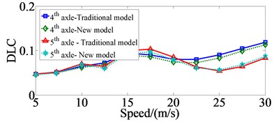
The vehicle speeds of 5 m/s, 7.5 m/s, 10 m/s, 12.5 m/s, 15 m/s, 17.5 m/s, 20 m/s, 22.5 m/s, 25 m/s, 27.5 m/s and 30 m/s were considered to compare the performance of two different types of the air suspension systems for reducing the negative impacts on the road surface when vehicle moves on the ISO level B road surface and full loaded. The DLC values at 2nd, 3rd and 4th, 5th axles of vehicle with the traditional and new dynamic models of the air suspension systems are shown in Fig. 2 and Fig. 3.
Fig. 2-3 show that the DLC values of wheels at 2nd, 3rd and 4th, 5th axles of vehicle with the new air suspension system are negligibly reduced at low- and high-speed conditions and which it is significantly reduced at average speed conditions, especially reduced by 9.3 %, 7.8 %, 7.0 % and 5.4 % at the vehicle speeds of 15 m/s, 17.5 m/s, 20 m/s and 22.5 m/s in comparison with the traditional air suspension system.
Fig. 2Comparing of the DLC values at 2nd and 3rd axles with traditional dynamic model and new dynamic model
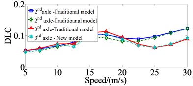
Fig. 3Comparing of the DLC values at 4th and 5th axles with traditional dynamic model and new dynamic model
4.2. Road surface conditions
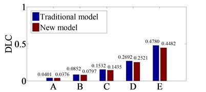
Five road surface conditions from level A (very good) to level E (very poor) in ISO/TC 80686 are used to compare the performance of two different types of the air suspension systems for reducing the negative impacts on the road surface when vehicle moves with a velocity of 20 m/s and fully loaded. The DLC values at 3rd and 5th axles of vehicle with the traditional and new dynamic models of the air suspension systems when vehicle moves on five different road surface conditions are shown in Fig. 4 and Fig. 5.
Fig. 4-5 show that the DLC values of wheels at 3rd and 5th axles of vehicle with the new air suspension system are reduced by 6.7 %, 7.0 %, 7.4 %, 7.7 %, 8.5 % and 6.6 %, 6.9 %, 6.8 %, 6.9 %, 6.6 %, respectively in comparison with the traditional air suspension system, when vehicle moves on the change of road surface condition from the ISO level A to level E road surface with a velocity of 20 m/s and fully loaded.
Fig. 4Comparing of the DLC values at 3rd axle with traditional and new dynamic model
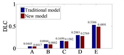
Fig. 5Comparing of the DLC values at 5rd axle with traditional and new dynamic model
5. Conclusions
In this study, the semi-trailer truck dynamic model with 14 degrees of freedom is developed with the dynamic models of the traditional and new air suspension systems to compare the performance of the air suspension systems for reducing the negative impacts on the road surface when vehicle moves on the different road conditions. The major conclusions that can be drawn from the analysis results as follows:
1) The DLC values of wheels at 2nd, 3rd and 4th, 5th axles of vehicle with the new air suspension system are negligibly reduced at low- and high-speed conditions and which it is significantly reduced at average speed conditions in comparison with the traditional air suspension system.
2) The DLC values of wheels at 3rd and 5th axles of vehicle with the new air suspension system are reduced by 6.7 %, 7.0 %, 7.4 %, 7.7 %, 8.5 % and 6.6 %, 6.9 %, 6.8 %, 6.9 %, 6.6 %, respectively in comparison with the traditional air suspension system.
References
-
Shi X. M., Cai C. S. Simulation of dynamic effects of vehicles on pavement using a 3D interaction model. Journal of Transportation Engineering, Vol. 135, 2009, p. 736-744.
-
Le Van Quynh, Zhang Jianrun, Liu Xiaobo, Wang Yuan Nonlinear dynamics model and analysis of interaction between vehicle and road surfaces for 5-axle heavy truck. Journal of Southeast University (Natural Science Edition), Vol. 27, Issue 4, 2011, p. 452-457.
-
Zhengchao Xie, Pak Kinwong, et al. A noise-insensitive semi-active air suspension for heavy-duty vehicles with an integrated fuzzy-wheelbase preview control. Mathematical Problems in Engineering, 2013, p. 121953.
-
Haider Abid J., Jie Chen, Ameen Nassar A. Equivalent air spring suspension model for quarter-passive model of passenger vehicles. International Scholarly Research Notices, 2015, p. 974020.
-
Presthus M. Derivation of Air Spring Model Parameters for Train Simulation. M.S. Thesis, Lulea University of Technology, 2002.
-
Fox M. N., Roebuck R. L., Cebon D. Modelling rollinglobe air springs. International Journal of Heavy Vehicle Systems, Vol. 14, Issue 3, 2007, p. 254-270.
-
Berg M. A three-dimensional air spring model with friction and orifice damping. Proceedings of the 16th IA VSD Symposium, the Dynamics of Vehicles on Roads and on Tracks, Pretoria, South Africa, 1999.
-
Dodds C. J., Robson J. D. The description of road surface roughness. Journal of Sound and Vibration, Vol. 31, Issue 2, 1973, p. 175-183.
-
International Organization for Standardization. ISO 8068 Mechanical Vibration-Road Surface Profiles-Reporting of Measured Data, 1995.
-
Cole D. J., Cebon D. Truck suspension design to minimise road damage. Journal of Automobile Engineering, Vol. 210, 1996, p. 95-107.
-
Rosnawati Buhari, Munzilah Md Rohani, Mohd Ezree Abdullah Dynamic load coefficient of tyre forces from truck axles. Applied Mechanics and Materials, Vol. 405, Issue 408, 2013, p. 1900-1911.
-
Lu Yongjie, Yang Shaopu, Li Shaohua, et al. Numerical and experimental investigation on stochastic dynamic load of a heavy duty vehicle. Applied Mathematical Modeling, Vol. 34, Issue 1, 2010, p. 2698-2710.
Cited by
About this article
The work described in this paper was supported by Thai Nguyen University of Technology for a Scientific Project (Code: T2016-54).

