Abstract
Under the interaction of the wheels of heavy-duty trucks on the random road surface when the vehicles are travelling, their generated vibrations not only affect the driver's ride comfort but also impact the road surface damage. To assess the vibration influence of different types of vehicles on the road surface damage, three dynamic models of the two axle, three axle, and four axle of heavy trucks have been build and computed via the Matlab/Simulink software. The dynamic tire load, dynamic load coefficient, and dynamic load-stress factor are chosen to assess the friendly load of different heavy trucks under the different operating conditions of the vehicle. The obtained result indicates that the dynamics parameters including suspension system, tires, and axle load distributions of heavy trucks have a greater effect on the dynamic tire force than the total weight of the vehicle. In order to ensure the road’s safety, the traffic management should intervene quickly to give a velocity limit for vehicles under the condition of the vehicle moving with the empty loaded on the poor road surface.
Highlights
- Three dynamic models of the two axle, three axle, and four axle of heavy trucks have been build to assess the vibration influence of different types of vehicles on the road surface damage.
- The dynamics parameters including suspension system, tires, and axle load distributions of heavy trucks have a greater effect on the dynamic tire force than the total weight of the vehicle.
- To ensure the road's safety, the traffic management should intervene quickly to give a velocity limit for vehicles under the condition of the vehicle moving with the empty loaded on the poor road surface.
1. Introduction
Nowadays, the heavy trucks play an important role in the transportation of goods for economic development. Therefore, the road surface damage and decrease of the ride comfort was mainly caused by the vehicle's loads in the traveling condition [1-4]. A dynamic model of the heavy truck using 5-axle of the wheels was established to analyze the influence of the speeds, random road surface, suspension systems, and wheel systems of the heavy vehicle on the minimal vertical dynamic load factor, the maximal vertical dynamic load factor, and the dynamic load stress factor [3]. Besides, based on multi-body dynamic theory for heavy-duty vehicles, a vehicle dynamic model was also established to evaluate the effect of the operating parameters of the speeds, loads, random road surfaces, and stiffness of the wheel on the dynamic loads and the dynamic load coefficients (DLC) of the wheels [1, 5-7]. Moreover, in order to reduce the dynamic tire load acting on the road surface, the design parameters of suspension systems of the heavy truck were also optimized [8, 9] and controlled based on the genetic algorithm and optimal control theory [10-14]. In addition, to reduce the excitation force between the wheel and random road surface, a 3-D vehicle-pavement coupled model to simulate the pavement dynamic loads induced by the vehicle-pavement interaction where both vehicle vibration and pavement deformation were considered. The effect of road surface conditions, vehicle parameters, and driving speed on the pavement dynamic loads were then analyzed. The impact factor, dynamic load coefficient, and frequency distribution of pavement loads were used to evaluate their impaction on the road-friendliness [2, 5]. However, these above studies mainly evaluated the effect of the wheel and road surface interaction of a heavy truck.
In reality, there are many different types of heavy trucks including two-axle vehicle, three-axle vehicle, four-axle vehicle, five-axle vehicle, and more axle vehicle; and the heavy vehicles running on the national highways increase not only the number of vehicles but also the vehicle load which are the major causes of road damage. Therefore, the major goal of this study is to establish the vibration model of the different heavy trucks for determining the dynamic wheel loads. A dynamic load-stress factor is used to evaluate the influence of the dynamic wheel loads on the highway road surface. Matlab/Simulink is used to simulate the vehicle vibration models and calculate the impact factors. From the vibration model, dynamic loads of the wheel, DLC, and dynamic load-stress factor are analyzed under the different vehicle speeds, vehicle loads, and road surface roughness, respectively.
2. Dynamics model of different heavy trucks
2.1. Vehicle’s dynamic model
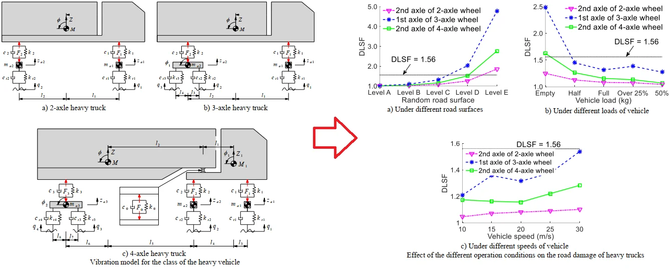
Three types of heavy trucks including two-axle vehicle, three-axle vehicle, and four-axle vehicle are chosen to evaluate the influence of the vibration of heavy trucks on road damage. The dynamic model of the heavy trucks with multiple degrees of freedom is built in Fig. 1, where and are the sprung mass of the heavy trucks (tractor and trailer); , , and are the unsprung mass of the front axle, the rear axle, and the tandem axle, respectively; and are the stiffness and damping coefficients of the suspension systems; and are the stiffness and damping coefficients of the wheels; and are the displacements of the sprung mass of the heavy trucks (tractor and trailer); and are the pitching angle of the sprung mass of the heavy trucks (tractor and trailer); is the vertical displacements at the centre gravity of the axles; and is the distance of the vehicle.
Fig. 1Vibration model for the class of the heavy vehicle
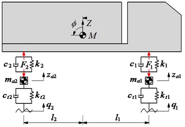
a) 2-axle heavy truck
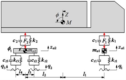
b) 3-axle heavy truck
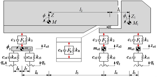
c) 4-axle heavy truck
2.2. Different vibration equations
To facilitate the description of the vehicle’s vibration via the computer simulation, a combined method of the multi-body system theory and D’Alembert’s principle is chosen to calculate the vibration equation of the heavy trucks. The multi-body system theory is used to separate the system into subsystems which are linked by the force and moment equations. D’Alembert’s principle is used to set up force and moment equations to describe the dynamic subsystems of the heavy trucks in Fig. 1 as follows.
The vibration equation of a 2-axle heavy truck:
where the force responses of the suspension systems of the vehicle and wheels of and are determined as in Eq. (2):
The vibration equation of a 3-axle heavy truck:
where the force responses of the suspension systems of the vehicle and wheels of and are determined as in Eq. (4):
The vibration equation of a 4-axle heavy truck:
where the force responses of the suspension systems of the vehicle and wheels of , , and are determined as in Eq. (6):
The differential Eqs. (1), (3), and (5) are given by the following matrix form:
where , , , , and are the mass matrix of the heavy truck, damping and stiffness matrix of the suspension systems, and damping and stiffness matrix of the wheels, respectively; is the displacement vector, and is the vibration excitation vector of the road surface.
2.3. Vibration excitation sources
The roughness of the highway road surface greatly affects the interaction between the wheel and road surface and the road damage. It plays an important role in evaluating dynamic interaction between vehicles and roads. The excitation of the random road surface is represented with a random process. The equation of the power spectrum density (PSD) of the random road is expressed as follows [8, 15]:
where is the wavelength’s reciprocal space frequency; is the reference space frequency, ( 0.1 m–1); is the PSD of road surface under the reference space frequency known as the road surface roughness coefficient; and is the frequency index that decides the frequency configuration of PSD of road surface ( 2).
The road surface roughness is assumed to be a zero-mean stationary Gaussian random process. It can be generated through an inverse Fourier transformation:
where is the random phase uniformly distributed from 0 to 2.
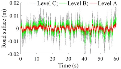
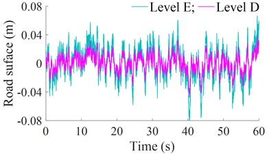
According to the standard ISO 8068 [15], five types of typical road surface roughness from ISO level A to E are applied to evaluate the road damage of heavy trucks. The simulation result of the typical road surface roughness from ISO level A to E is shown in Fig. 2.
Fig. 2The vibration excitation of the road surface roughness from ISO level A to E
3. The damage index of road
Based on the existing research, the damage index of the road surface was evaluated based on the index of the dynamic load-stress factor (DLSF) [16, 17]. This index was calculated based on the road damage criteria is used to quantify the road load caused by dynamic road-tire forces. The DLSF value is given by [16, 17]:
where is defined as the dynamic load coefficient of the wheel-road surface interaction, is the root mean square of the vertical dynamic load of the wheel, and is the static load of the wheel [1, 2, 6].
The DLSF is strongly dependent on the vehicle’s design parameters as well as the operating conditions of the vehicle. According to Refs. [1, 14], if the DLSF ≤ 1.56, this means that the road-friendly limit for the dynamic parameters of a vehicle and the operation conditions of the vehicle will be established.
4. Simulation result and evaluation
To compute the differential equations in Eqs. (1), (3), and (5) for evaluating the influence of the dynamic load of the heavy truck on the road damage of the highway road surface, based on the design parameters of all the heavy trucks listed in Tables 1, 2, and 3, Matlab/Simulink software is used to simulate and calculate the results under the condition of the heavy trucks is moving on the random road surface of the ISO level C at 72 km/h.
Table 1The design parameters of two-axle heavy truck
Parameter | Value | Parameter | Value | Parameter | Value |
(kg) | 6451 | (N/m) | 1.138×10⁶ | (N/m) | 0.876×10⁶ |
(kg) | 297 | (Ns/m) | 15.00×10³ | (Ns/m) | 2.00×10³ |
(kg) | 524 | (Ns/m) | 15.00×10³ | (Ns/m) | 2.00×10³ |
(N/m) | 0.198×10⁶ | (N/m) | 0.788×10⁶ | , (m) | 3.79, 2.31 |
Table 2The design parameters of three-axle heavy truck
Parameter | Value | Parameter | Value | Parameter | Value |
(kg) | 7730 | (Ns/m) | 66.88×10³ | (Ns/m) | 3.00×10³ |
(kg) | 561 | (N/m) | 1.00×10⁶ | (m) | 3.79 |
(kg) | 899 | (N/m) | 1.00×10⁶ | (m) | 2.31 |
(N/m) | 7.35×10⁶ | (N/m) | 1.00×10⁶ | (m) | 0.86 |
(N/m) | 2.056×10⁶ | (Ns/m) | 3.00×10³ | (m) | 0.86 |
(Ns/m) | 4.55×10³ | (Ns/m) | 3.00×10³ |
Table 3The design parameters of four-axle heavy truck
Parameter | Value | Parameter | Value | Parameter | Value |
(kg) | 12460 | (Ns/m) | 10.0×10³ | (Ns/m) | 3.00×10³ |
(kg) | 2659 | (Ns/m) | 84.0×10³ | (m) | 2.712 |
(kg) | 400 | (Ns/m) | 200×103 | (m) | 4.843 |
(kg) | 553 | (N/m) | 1.03×10⁶ | (m) | 0.778 |
(kg) | 792 | (N/m) | 2.06×10⁶ | (m) | 2.712 |
(N/m) | 2.32×10⁶ | (N/m) | 2.06×10⁶ | (m) | 2.131 |
(N/m) | 8.60×10⁶ | (N/m) | 2.00×10⁶ | (m) | 2.357 |
(N/m) | 2.00×10⁶ | (Ns/m) | 3.00×10³ | (m) | 0.50 |
(N/m) | 20.0×10⁶ | (Ns/m) | 3.00×10³ | (m) | 0.50 |
(Ns/m) | 2.20×10³ | (Ns/m) | 3.00×10³ |
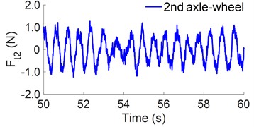
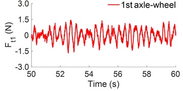
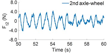
Under the full load condition of the heavy trucks, the simulation and calculation results of the , DLC, and DLSF of the heavy trucks have been listed in Table 4. The calculation results show that the at 2nd axle of the 2-axle vehicle, 1st axle of the 3-axle vehicle, and 2nd axle of the 4-axle vehicle has the maximum value. Their dynamic load responses have been plotted in Fig. 3.
These results are similar to the results in Refs. [1, 14]. Under the influence of the maximum dynamic load of the wheel acting on the road surface of the heavy truck, both the values of DLC and DLSF at 2nd axle of the two-axle vehicle, 1st axle of the three-axle vehicle, and 2nd axle of the four-axle vehicle are also maximum. This means that the dynamic load of the wheel at 2nd axle of the two-axle vehicle, 1st axle of the three-axle vehicle, and 2nd axle of the four-axle vehicle greater affects the road damage than other axles of heavy trucks. Besides, the results of the DLC and DLSF in Table 4 also show that the values of DLC and DLSF at 1st axle of the three-axle vehicle are higher than that of 2nd axle of the two-axle vehicle and 2nd axle of the four-axle vehicle. This means that the vehicle's design parameters such as suspension systems, tires, and axle load distribution have a greater effect on the dynamic tire load than the total weight of the vehicle. However, this study will focus on analyzing the influence of the operation conditions of heavy trucks on the DLSF and this problem will be continued to discuss in the following section.
Table 4Different dynamic loads at the axles of the different heavy trucks
Parameter | Axle location | Heavy trucks | ||
2-axle vehicle | 3-axle vehicle | 4-axle vehicle | ||
(N) | 1st axle | 1734.8 | 7747.3 | 14.173 |
2nd axle | 5172.9 | 3528.4 | 19.006 | |
3rd axle | 3529.8 | 8.882 | ||
4th axle | 9.044 | |||
DLC | 1st axle | 0.0645 | 0.2264 | 0.1608 |
2nd axle | 0.1163 | 0.1262 | 0.1619 | |
3rd axle | – | 0.1262 | 0.0902 | |
4th axle | – | – | 0.0918 | |
DLSF | 1st axle | 1.0250 | 1.3154 | 1.1571 |
2nd axle | 1.0818 | 1.0963 | 1.1593 | |
3rd axle | – | 1.0963 | 1.0490 | |
4th axle | – | – | 1.0508 | |
Fig. 3Maximum dynamic load of the wheel axle acting on the road surface
a) 2-axle heavy truck
b) 3-axle heavy truck
c) 4-axle heavy truck
4.1. Under the different road surfaces
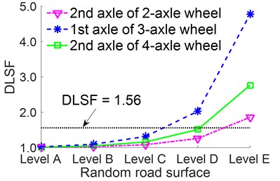
The road surface roughness not only affects the ride comfort as well as the durability of the part of heavy trucks but also affects the dynamic wheel load. To analyze the effect of the road surface roughness on the DLSF, five types of the random road of ISO level A to ISO level E are simulated when heavy trucks are moving at 72 km/h under the full load condition. The DLSF influenced by the different qualities of the road surfaces are shown in Fig. 4(a). The result shows that the DLSF increases quickly when the vehicle moves on the condition of the bad road surfaces of ISO level D and E, and this makes the negative influences on the random road surface, especially with the three-axle heavy truck.
According to Refs. [1, 14], if the DLSF ≤ 1.56, this means that the road-friendliness limit needs to be established. Thus, the condition of the random road surface of ISO level C for the three-axle heavy truck moving and the road surface condition of level D for two-axle and four-axle heavy trucks moving (the value of DLSF < 1.56) is selected as the intervention limit for the random road surfaces. In this circumstance, the traffic management needs to quickly intervene to give a safe velocity limit for heavy trucks when they move on these road surfaces, concurrently, these road surfaces need to be repaired.
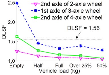
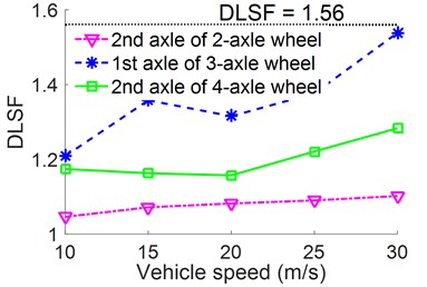
Fig. 4Effect of the different operation conditions on the road damage of heavy trucks
a) Under different road surfaces
b) Under different loads of vehicle
c) Under different speeds of vehicle
4.2. Under the different loads of the vehicle
The vehicle loads not only affect the durability of the vehicle but also affect the random road surface’s fatigue life. In order to analyze the effect of the vehicle loads on the damage of the random road surface, the different load values of heavy trucks as empty load, half load, full load, overload 25 %, and overload 50 % are computed under the same simulation condition in Section 4.1. The simulation result of DLSF with different vehicle loads is plotted in Fig. 4(b). Fig. 4(b) shows that the values of DLSF at axles of heavy trucks increase most quickly when heavy trucks move under the empty load condition and half load condition, especially with the three-axle heavy truck. Thus, it has negatively affected the road surface. When heavy trucks move at overload 25 % and 50 % conditions, the values of DLSF at axles of heavy trucks significantly reduce and it reduces the road damage. However, it has no benefit to the durability of the part of the vehicle and the safe movement of the vehicle. If the vehicle load keeps increasing to some large value, it will no longer affect the DLC and DLSF. Moreover, heavier vehicles will increase the absolute magnitude of dynamic loads, which is the direct cause of road surface damage [15]. Therefore, to reduce the negative effects of this case caused on the road surface, the traffic management needs to quickly intervene to give a safe velocity limit for vehicles when they move on this condition.
4.3. Under the traveling velocities of the vehicle
The vehicle’s moving speed is one of the important causes of the damage of the road surface. To analyze the effect of the vehicle speed on the damage of the road surface, the speed values of heavy trucks including {10, 15, 20, 25, 30} m/s are simulated under the same condition of Section 4.2. The result of the DLSF with different vehicle speeds is plotted in Fig. 4(c). Fig. 4(c) indicates that when the speed of the vehicle is 20 m/s, the DLSF is quickly increased in the direction of the unfriendly road, especially with the three-axle heavy truck. Therefore, the vehicle’s moving speed need to be limited, especially under the condition of the heavy truck moving on the road surface of ISO level C, D, and E.
5. Conclusions
Based on the research result of the dynamic models of the two-axle vehicle, three-axle vehicle, and foru-axle vehicle, the design parameters of the suspension systems and wheels; and the load distribution of axle-wheels greatly affect the dynamic tire force while the total weight of the vehicle insignificantly affect. Therefore, the systems of the heavy trucks should be desinged to evenly distribute the dynamic load on the wheel axles.
The empty loaded condition of heavy trucks greatly affects the road surface damage, thus, to ensure the safety of the road surface, the traffic management needs to quickly intervene to give the limiting speed for vehicles when the vehicles are traveling as empty loaded condition and the poor road surface condition.
This study not only provides a reference for assessing the influence of heavy trucks on the road-friendliness, but also provides important warning limits for the design of dynamic systems. of heavy trucks to improve safety and reduce road damage.
References
-
Y. Lu, S. Yang, S. Li, and L. Chen, “Numerical and experimental investigation on stochastic dynamic load of a heavy duty vehicle,” Applied Mathematical Modelling, Vol. 34, No. 10, pp. 2698–2710, Oct. 2010, https://doi.org/10.1016/j.apm.2009.12.006
-
T. Gillespie and S. Karamihas, “Simplified models for truck dynamic response to road inputs,” International Journal Vehicle Design, Vol. 7, No. 1, pp. 52–63, 2000.
-
V. Nguyen, R. Jiao, and J. Zhang, “Control performance of damping and air spring of heavy truck air suspension system with optimal fuzzy control,” SAE International Journal of Vehicle Dynamics, Stability, and NVH, Vol. 4, No. 2, pp. 179–194, Feb. 2020, https://doi.org/10.4271/10-04-02-0013
-
Y. Chen, J. He, M. King, W. Chen, and W. Zhang, “Effect of driving conditions and suspension parameters on dynamic load-sharing of longitudinal-connected air suspensions,” Science China Technological Sciences, Vol. 56, No. 3, pp. 666–676, Mar. 2013, https://doi.org/10.1007/s11431-012-5091-3
-
X. M. Shi and C. S. Cai, “Simulation of dynamic effects of vehicles on pavement using a 3D interaction model,” Journal of Transportation Engineering, Vol. 135, No. 10, pp. 736–744, Oct. 2009, https://doi.org/10.1061/(asce)te.1943-5436.0000045
-
D. J. Cole and D. Cebon, “Truck suspension design to minimize road damage,” Proceedings of the Institution of Mechanical Engineers, Part D: Journal of Automobile Engineering, Vol. 210, No. 2, pp. 95–107, Apr. 1996, https://doi.org/10.1243/pime_proc_1996_210_251_02
-
J. R. Kilner, “Pneumatic tire model for aircraft simulation,” Journal of Aircraft, Vol. 19, No. 10, pp. 851–857, Oct. 1982, https://doi.org/10.2514/3.44786
-
W. Wang, Y. Song, Y. Xue, H. Jin, J. Hou, and M. Zhao, “An optimal vibration control strategy for a vehicle’s active suspension based on improved cultural algorithm,” Applied Soft Computing, Vol. 28, pp. 167–174, Mar. 2015, https://doi.org/10.1016/j.asoc.2014.11.047
-
L. Sun, “Optimum design of “road-friendly” vehicle suspension systems subjected to rough pavement surfaces,” Applied Mathematical Modelling, Vol. 26, No. 5, pp. 635–652, May 2002, https://doi.org/10.1016/s0307-904x(01)00079-8
-
M. Peter, “Active suspension of a heavy-vehicle driven axle,” Journal of Mechanical Engineering, Vol. 53, pp. 342–350, 2022.
-
G. Tsampardoukas, C. W. Stammers, and E. Guglielmino, “Hybrid balance control of a magnetorheological truck suspension,” Journal of Sound and Vibration, Vol. 317, No. 3-5, pp. 514–536, Nov. 2008, https://doi.org/10.1016/j.jsv.2008.03.040
-
Z. Xie, P. K. Wong, J. Zhao, T. Xu, K. I. Wong, and H. C. Wong, “A noise-insensitive semi-active air suspension for heavy-duty vehicles with an integrated fuzzy-wheelbase preview control,” Mathematical Problems in Engineering, Vol. 2013, No. 8, pp. 1–12, 2013, https://doi.org/10.1155/2013/121953
-
J. Máca and M. Valášek, “Vibration control of bridges under moving loads,” Slovak Journal of Civil Engineering, Vol. 3, No. 4, pp. 1–4, 2006.
-
K. Yi and J. K. Hedrick, “Active and semi-active heavy truck suspensions to reduce pavement damage,” SAE International Truck and Bus Meeting and Exposition, Vol. 43, No. 3, pp. 397–384, Nov. 1989, https://doi.org/10.4271/892486
-
“ISO 8068. Mechanical vibration-Road surface profiles-Reporting of measured data,” International Organization for Standardization, 1995.
-
C. Dodds and J. Robson, “The description of road surface roughness,” Journal of Sound and Vibration, Vol. 31, No. 2, pp. 175–183, 1973.
-
D. Cebon, Handbook of Vehicle-Road Interaction. Lisse: Netherlands Swets-Zetinger Press, 1999.
About this article
This study is supported by the Key Scientific Research Project of Hubei Polytechnic University (No. 22xjz02A).
The datasets generated during and/or analyzed during the current study are available from the corresponding author on reasonable request.
The authors declare that they have no conflict of interest.
